wideband (UWB) technology with operating band (3.1â10.6. GHz) is an attractive ..... of Microwave and Wireless Technologies, vol.7, no. 6, pp.661-669, Dec.
International Journal of Scientific & Engineering Research, Volume 7, Issue 6, June-2016 ISSN 2229-5518
675
Electronically switchable lowpass/bandpass Filter with Controlled Bandwidth using Pin DiodeLoaded stubs Hesham A.Mohamed1 and Ashraf S. Mohra1
Abstract— Electronically switchable and reconfigurable microwave devices such as filters are in great demand for wireless communication systems. The switchable Lowpass/Bandpass filter (LPF/BPF) can be used to control the spectrum of proposed signals and support multiple information channels. The PIN diodes are used to achieve exchange between the lowpass filter and bandpass filter with tunable bandwidth. The lowpass filter concept is demonstrated by ninth-order Chebyshev-type using stepped impedance resonators. as the number of diodes used increase as the roll off at the two 3dB frequency for bandpass is modified, with a little decrease in the bandwidth due to the shift of lower 3dB frequency to higher value, while the upper 3-dB frequency is nearly remain constant around 11 GHz. The switchable LPF/BPF is designed, fabricated and measured. Experimental results are in good agreement with the simulated results for each of the lowpass and bandpass filters response. Index Terms— Lowpass filter, Bandpass filter, RF PIN diode, stepped impedance resonators (SIRs), switchable.
—————————— ——————————
1 INTRODUCTION
T
HE electronically switchable and reconfigurable microwave devices that using PIN-diodes are essential components in the front-end circuits, cognitive radios, and wireless communication systems. Articles [1]-[8] describe the integrating of diodes with bandpass filters to reduce the circuit size and achieve the switch mechanism with favourable selectivity. In [1], the diode loaded resonators were used to design single-band wide stopband switchable filters. The switchable multi-Mode bandpass filters given in [2-3] were successfully realized in monolithic microwave integrated circuit (MMIC) technology. In [4], the switchable parallel coupled line bandpass filter used diodes loaded to turn on/off the passband and produce the transmission zeros to improving the stopband responses. For switching between different multiband applications, a compact dual-band bandpass filter was proposed in [5]-[6]. The authors in [7]-[8] designed two independent filters to switch between them to achieves the reconfigurable on-state frequency responses. At [9], a switchable filter between two different order Chebyshev responses was described. Based on the theory of Chebyshev response, the selectivity and stopband rejection level in the proposed switching circuit can be easily predicted before designing each filter. The ultrawideband (UWB) technology with operating band (3.1–10.6 GHz) is an attractive technology for local area networks (LAN), positioning and tracking for antennas, phase shifter and radar systems [10]. Ultra-wideband applications attract increasing attention, both in industry and academia, due to increasing levels of sophistication and demand for advanced communication systems. It has the characteristics of low cost, low weight, high data transmission rate and very low power consumption. The recent advances of materials and fabrication technologies have stimulated the rapid development in filters. In the meantime, advances in computer-aided design (CAD) tools such as full-wave electromagnetic (EM) simulators have revolutionized filter design. In this work, a new class of microwave planar filters with switchable between lowpass and bandpass filter is given. The
switchable lowpass/bandpass filter was achieved using Chebyshev type and short circuit stubs loaded by PIN diodes. The bandwidth of the bandpass filter response can be controlled with the number of PIN diodes loaded on short circuit stubs. The filter was design on RT/Duroid 5880 (ε r =2.2, h=0.7874 mm, tan δ=0.0009) and simulated using readymade CST software package. The measurement of the realized filter are in good agreement with the simulated results.
IJSER
2 THEORY AND CIRCUIT DESIGN The design of lowpass filter involves two main steps: one is to select an appropriate lowpass prototype (g values), second the transformation of g values to lumped L–C elements for the desired cutoff frequency and the desired source impedances. The prototype g-values for the lowpass prototype with Chebyshev filter can calculated as follows [9]: (1) g 0 = 1.0
gi =
1 4 sin(( 2i − 1)π / 2n ). sin(( 2i − 3)π / 2n ) ,i=1,2,3.. (2) gi −1 γ 2 + sin2 ((i − 1)π / n )
1.0 for n odd g i +1 = 2 coth ( β / 4 ) for n even β = ln[Coth( L AR / 17.37 )]
γ = sinh( β / 2n )
(3) (4) (5)
Where n is the number of g-values which can be defined as
n ≥ cosh −1
(10 0.1L AS − 1) /(10 0.1L AR − 1) cosh −1 Ω S
(6)
(7) Ω S = ω S / ωC Where, f c is the cutoff frequency, f S is the frequency at stopped attenuation, L AS is the stopped attenuation in (dB) and L AR is the ripple value in (dB). As a design example, choose the cutoff frequency as 11.2 GHz and the attenuation at F s =14.5 GHz
IJSER © 2016 http://www.ijser.org
International Journal of Scientific & Engineering Research, Volume 7, Issue 6, June-2016 ISSN 2229-5518
is L AS =30 dB, while the ripple is L AR =0.05 dB. Using the above equations, the number of filter elements will be nine (n=9) and the g values for the prototype will be as given in Tab. 1. Make a transformation for the g value to the lowpass lumped L-C elements based on the following equations [9]:
Li = ( g i Z o / ωC )
(8.a)
Ci = ( g i / ωC Z o )
(8.b)
So the corresponding lumped inductances and capacitances (L-C) values will be as shown in Tab. 1. With representing the inductance as high impedance transmission line (Z H =130Ω, W 1 =0.36 mm), the corresponding lengths will based on the following equation:
li = ( lH l 2π ) sin −1 (ωc Li / Z H )
676
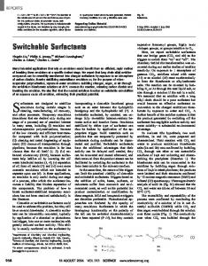
stubs will be described, Fig.3. The PIN diode used in the design is HPND 4005[11], where its equivalent circuit is shown in Fig.4 (a), where L s = 0.7 nH, R on =4.7 Ω and C off =0.017 pF which are the parasitic series inductor, forward biased resistor and reverse biased capacitor, respectively. The diode characteristics is stable up to 12 GHz which is suitable for the ultra wideband range. When the diode terminals is connected with metal wire leads for biasing, the response may be changed, so we use the bias Tee for biasing the diodes without needs to metal terminals. Figure 4 (b) shows the Bias Tee electrical scheme [12]. Figure 1: Chebyshev stepped impedance lowpass f
(9) Figure 1: Chebyshev stepped impedance lowpass filter layout
With representing the capacitor with low impedance transmission line (Z L =25Ω, W 2 =6.121 mm), the corresponding lengths will based on the following equation:
li = ( lL / 2π ) sin −1 (ωcCi Z L )
(10)
IJSER
For the design on RT/Duroid 5880 Teflon substrate (ε r =2.2, h=0.7874 mm and tan δ=0.0009), the corresponding lengths for each of inductance and capacitance are calculated using Eqs. (9-10). Due to microstrip tolerance and limited ratio of (Z H / Z L ) that can be achieved with using microstrip technology, the values of L and C are optimized to achieve the required performance as shown in Tab.1. The layout of the stepped impedance lowpass filter is shown in Fig.1. By ADS and CST, the simulation results for the designed lowpass filter gives (-0.245 dB), (