optical quality of the lens makes it applicable in Blu-ray. Disc drives to enable dual layer reading/writing. 2. Electrowetting Lens Principle. Our electrowetting lens ...
OPTICAL REVIEW Vol. 12, No. 3 (2005) 255–259
Electrowetting-Based Variable-Focus Lens for Miniature Systems B. H. W. HENDRIKS, S. K UIPER, M. A. J.
VAN
A S, C. A. R ENDERS and T. W. TUKKER
Philips Research Laboratories, Prof. Holstlaan 4, 5656 AA Eindhoven, The Netherlands (Received October 12, 2004; Accepted April 8, 2005)
The meniscus between two immiscible liquids of different refractive indices can be used as a lens. A change in curvature of this meniscus by electrostatic control of the solid/liquid interfacial tension leads to a change in focal distance. It is demonstrated that two liquids in a tube form a self-centred variable-focus lens. The optical properties of this lens were investigated experimentally. We designed and constructed a miniature camera module based on this variable lens suitable for mobile applications. Furthermore, the liquid lens was applied in a Blu-ray Disc optical recording system to enable dual layer disc reading/writing. # 2005 The Optical Society of Japan Key words: liquid lens, electrowetting, camera, optical recording
1.
Incident light
Introduction
(A)
A lens system capable of focusing is widely used in various optical systems. A well-known example is focusing in cameras. Small-sized cameras for imaging applications, such as credit card cameras and mobile phone cameras, form a fast growing market. Due to the introduction of megapixel resolution sensors in such cameras, focusing is required to fully exploit the resolution of the camera for the required range of object distances. Scaling down conventional motordriven focusing systems is not suitable, mainly because of cost and robustness requirements for mobile applications. Another example of a focusing system is present in diffraction-limited optics requiring high optical quality components such as dual-layer Blu-ray Disc optical recording system.1–3) A way to achieve dual-layer readout is by moving a lens in front of the objective lens in order to change the vergence of the beam.4) These displacements are relatively large compared to the diameter of the beam. A new way of achieving variable focus was demonstrated by Gorman et al.5) They showed that a drop of liquid changes its shape and thus its optical power by using the principle of electrowetting. By applying a voltage across a self-assembled monolayer between the drop and an underlying transparent electrode, the solid/liquid interfacial tension and thus the curvature of the drop could be changed. Berge and Peseux6) studied the switching behaviour of this lens further in the case where an insulating layer is used instead of the self-assembled monolayer. A drawback of the drop-lens is the lack of a simple concept to keep the drop centred on the optical axis. Here we present a new electrowetting lens design concept that simply solves the centering problem and has excellent switching behaviour with good optical properties, and that can meet the low cost and robustness requirements for mobile applications. A camera module based on the variable liquid lens is presented. Furthermore, we show that the good optical quality of the lens makes it applicable in Blu-ray Disc drives to enable dual layer reading/writing. 2.
Hydrophobic coating Insulator
(C)
Insulating fluid
R
Electrodes
Glass
Conducting fluid
(B)
(D)
θ
V
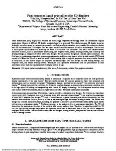
Fig. 1. (A) Schematic cross section of a liquid-based variable lens in a cylindrical housing. (B) Under application of a voltage charges accumulate in the wall electrode whereas opposite charges are induced in the conducting liquid near the solid/liquid interface. (C) Photograph of a 6-mm diameter electrowetting lens without voltage applied and (D) when a voltage is applied.
manipulated in a cylindrical tube by changing the curvature of the interface (meniscus).7) Keeping the amount of fluids constant when switching the meniscus results in a variable lens formed by a self-centered meniscus.8) In Fig. 1 a schematic cross section of the newly proposed lens is shown. Two immiscible liquids, one conductive (for instance salted water) and the other one nonconductive (for instance a transparent nonpolar oil) having different refractive indices and approximately the same density, are confined in a cylindrical housing. Due to this density matching of the two liquids the lens is insensitive to shocks and vibrations. The cylinder is first coated with an electrode followed by an insulating and a hydrophobic coating. Also one of the transparent sealing plates of the cylinder is coated with a hydrophobic coating. The other sealing plate is (partly) covered with an electrode, insulated from the electrode of the cylinder. Applying a voltage across both electrodes effectively influences the interfacial tension between the conductive liquid and the insulator, resulting in a change in the radius of the meniscus [see Figs. 1(A) and 1(B)]. The cylindrical geometry ensures that this meniscus remains centered on the cylinder axis. In Figs. 1(C) and 1(D) two photographs of the lens in two switching states are
Electrowetting Lens Principle
Our electrowetting lens design is a spin off of the work carried out at our laboratory on liquid control in tubes by electrocapillary pressure, in which two immiscible fluids are 255
256
OPTICAL REVIEW Vol. 12, No. 3 (2005)
B. H. W. HENDRIKS et al.
shown, demonstrating the principle of the lens. The electrowetting lens acts as a capacitor displaying typically 100 pF capacitance in case of a 3 mm diameter lens. The driving voltage is typically of the order of 50– 100 V for a full-range switch, resulting in an energy of only 0.5 mJ per switch. The lens consumes no energy to keep its shape. The switching speed for such a lens is typically 10 ms. To avoid freezing of the water, salt can be added to depress the freezing point. We have shown that freezing point depression of water below �40� C is possible. 3.
Optical Power and Quality
Two important properties of the liquid lens are the optical power change and the optical quality. According to theory the interface between the two liquids forms a perfect sphere in all switching states. In the unaddressed state, the mensicus of the liquid lens described in Sect. 2 forms a half sphere with radius R equal to the inner radius of the cylinder (contact angle � of 180� ). When fully addressed a contact angle � of 60� can be reached. The difference in refractive index (�n) between salted water and the oil is typically of the order of �n ¼ 0:15. The optical power D of the liquid lens is given by D¼
�n : R
ð1Þ
For a liquid lens having an inner diameter of 3 mm the optical power can be controlled between �100 and þ50 diopters. To study the optical quality, the liquid lens is placed in a Twyman–Green interferometer. In particular, we investigate the deformation of the mensicus from a perfect sphere. As long as the interface between the two liquids is well-defined, an optical system can be made having high optical quality. Deviations of the interface from the spherical shape due to manufacturing errors such as variations in the coating thickness and deviations from the cylindrical shape of the container, result in unintended wavefront aberrations deteriorating the quality of the optical system. Here we investigate these deviations. Table 1 shows the root-mean-square optical path difference (OPDrms ) for the astigmatism and coma wavefront aberration measured on a liquid lens, having inner cylinder diameter of 5.5 mm, over a pupil diameter of 3 mm at
Fig. 2. Fringe pattern measured at 405 nm wavelength over a diameter of 3 mm when the meniscus is flat revealing a wavefront aberration of 0.031 waves OPDrms .
405 nm as a function of the relative switching voltage (V=Vflat ), with Vflat the voltage at which the meniscus is flat. In Fig. 2 the corresponding measured interferogram fringe pattern when the meniscus is flat is shown. The table shows that in the off-state a significant amount of astigmatism is present, but when the lens is slightly addressed, it reduces to well below the diffraction limit of 70 m�. Switching the lens further the astigmatism finally decreases to zero. In this state coma is the dominant wavefront aberration. Apart from the initial value the dependence of the astigmatism is among others related to the deviation of the interior of the tube from a perfect cylinder. When the meniscus is perpendicular to the wall (flat), the shape of the wall has no influence as long as the wall is translational invariant along the tube axis. The more the meniscus is curved the larger the influence of the wall deformations. Coma is related to the uniformity of the coating applied on the interior wall. Typically when a certain part of the interior wall wets better coma will arise. The above results show that the asymmetrical wavefront aberrations can be controlled well below the diffraction limit of 70 m� over the full switching range (except initial state in this example), enabling the application of such a lens in high optical quality systems such as optical recording. 4.
Table 1. OPDrms astigmatism, coma and total asymmetrical wavefront aberrations measured over a pupil radius of 3 mm at 405 nm as a function of the relative switching voltage. V=Vflat
Astigmatism (m�)
Coma (m�)
Total asymmetrical (m�)
0.0 0.31
316
52
328
34
56
67
0.41
36
31
53
0.52
16
11
20
1.0
0
28
31
Application in Miniature Camera
We used the electrowetting lens described in the previous sections to manufacture a miniaturized camera based on a VGA CMOS sensor (640 � 480 pixels with size 5:0 � 5:0 mm2 ).8) In Table 2 the design specification is listed. The electrowetting lens is enclosed between two injectionmoulded plastic lenses. The outer diameter of the cylinder of the electrowetting lens is 4 mm and the inner diameter 3 mm, while the height is 2.2 mm. On one side the cylinder is closed by a glass plate and on the other side by a truncated glass sphere mounted on a metal membrane, resulting in a building height of the total lens stack of only 5.5 mm measured from the image sensor to the top of the first lens.
OPTICAL REVIEW Vol. 12, No. 3 (2005)
B. H. W. HENDRIKS et al.
Table 2. Design parameters camera module. Parameter
Value
VGA CMOS sensor Pixel size
640 � 480 pixels 5:0 � 5:0 mm2
Field of view F-number
257
(A)
60� 2.5
Building height
5.5 mm
Focus range
2 cm–1
(A) Plastic lens Glass lens
(B)
Meniscus Plastic lens Sensor
(B) Fig. 4. Photographs taken with the research prototype camera module containing an electrowetting lens for (A) object at 50 cm distance and (B) an object at 2 cm distance.
Fig. 3. (A) Schematic view of a the optical design of the camera module and (B) photograph of an assembled research prototype camera module containing a liquid lens for focusing.
The resolution of the camera is limited by the pixel size of the sensor rather than that of the designed lens stack. In Fig. 3 a photograph of an assembled research prototype camera module is shown. The two electrical contacts to drive the lens are made on the top of the module in this prototype for simplicity reasons. In Fig. 4 two images are presented, taken with the camera module focused on an object nearby and far away, thus demonstrating the focusing function of the camera module. Exposing the liquid lens of the camera module to 1000 times the earth gravitation force had no permanent effect on the lens. 5.
Application in Optical Recording
In a Blu-ray Disc optical drive1–3) (capable of storing 25 GB on a single layer 12 cm disc) information on an optical record carrier with 0.1 mm cover layer is read or written making use of a blue laser (405 nm) and an objective
lens having a numerical aperture of NA ¼ 0:85. In Fig. 5 a schematic drawing of an optical pickup is shown. Linearly polarised light emitted by the laser is collimated by a collimator lens. The beam is transmitted by the polarising beam splitter and becomes circularly polarised after passing through the �=4-plate. It is focused by the objective lens on the information layer of the disc. Upon reflection the beam changes handedness of polarization and after passing through the objective lens and �=4-plate, it is turned into a beam with linear polarisation perpendicular to the original incoming beam. The beam is now reflected by the polarising beam splitter towards the detector. When the information is stored in two layers, switching from one layer to the other introduces spherical aberration due to the difference in cover layer thickness. A dual-layer disc contains two information layers separated by typically 0.025 mm, hence the first information layer has a cover layer of 0.075 mm and the second a cover layer of 0.1 mm thickness. An objective lens designed to readout information through a cover layer of 0.1 mm will give rise to a significant amount of spherical aberration when reading out the other layer covered only by a 0.075 mm thick layer (typically 235 m� OPDrms wavefront aberration). There are several ways to compensate for this spherical aberration. One way is by changing the vergence of the beam entering the objective lens. To achieve this vergence change, one can displace the collimator lens4) [see Fig. 5(A)]
258
OPTICAL REVIEW Vol. 12, No. 3 (2005)
(A)
B. H. W. HENDRIKS et al.
Detector
Servo lens
Disc
(Moving) Collimator Objective Laser
λ/4
PBS
(B)
Fig. 6. Photograph of a Blu-ray Disc optical pickup unit with a liquid lens mounted in front of the objective lens.
Detector
Servo lens
Disc
Collimator Objective Laser
PBS
Liquid lens
λ/4
Fig. 5. Schematic drawing of a Blu-ray Disc optical pickup. (A) In order to enable dual layer disc readout, displacement of the collimator can be employed to change the vergence of the beam entering the objective. (B) Instead of displacing the collimator a liquid lens can be placed between the collimator and the objective allowing beam vergence changes by changing the radius of curvature of the meniscus of the liquid lens.
or add a telescope construction between the collimator and the objective lens. A drawback of these methods is the large stroke required, typically a few millimeters. Here we demonstrate that this vergence change can also be achieved by employing a liquid lens between the collimator lens and the objective lens [Fig. 5(B)]. In Fig. 6 a photograph of the liquid lens in the optical pickup unit is shown. The cylinder has an inner diameter of 5.5 mm. By changing the radius of curvature of the meniscus of the liquid lens, we can change the vergence of the radiation beam. For a flat interface the beam is unaffected and the layer corresponding to the cover layer of 0.1 mm can be read out. For reading out the other layer we slightly curve the interface between the two liquids. The liquid lens used in the experiment contained salted water and oil with refractive index 1.334 and 1.540, respectively. The two liquids were density matched in order to eliminate gravity effects. The water was facing the disc in the setup. To compensate the spherical aberration when reading out the information layer at 0.075 mm depth the mensicus has a radius of �51:4 mm resulting in a slightly converging beam towards the object lens. The information at 0.1-mm depth is read out with the
Fig. 7. Eye pattern of the readout signal when the liquid lens in the optical path in case of (A) the 0.1 mm and (B) the 0.075 mm cover layer thickness.
meniscus being flat. Without the liquid lens the measured data-to-clock jitter of the test setup is 7.8% when reading out the information layer at 0.1 mm depth of a 50 GB dual layer ROM disc, while the layer at 0.075 mm could not be read. After inserting the liquid lens and switching the mensicus to a flat interface we measured a data-to-clock jitter of 10.6%. By curving the mensicus of the liquid lens also the layer at 0.075 mm could be read out, resulting in a jitter of 11.6%. The eye patterns of the readout signals for both layers are shown in Fig. 7. Although the jitter values with the liquid lens should be
OPTICAL REVIEW Vol. 12, No. 3 (2005)
further improved in order to make the optical recording system more robust, these first results demonstrate the good optical quality of the liquid lens enabling readout of dual layer Blu-ray Disc discs. 6.
Conclusion
A new electrowetting lens design concept has been presented allowing the construction of a miniature variable-focus camera. The robustness, simple construction, low power and good optical quality make this variable-focus camera especially suited for mobile applications. Furthermore, the good optical quality and stability of the liquid lens are demonstrated by employing a liquid lens in a Blu-ray Disc optical recording system enabling dual layer readout.
B. H. W. HENDRIKS et al.
259
Acknowledgment We thank C. A. N. van der Vleuten, H. Derks, W. J. Weekamp, C. Verberne, I. Helwegen and K. Renkema for their technical contribution. References
1) 2) 3) 4) 5) 6) 7) 8)
I. Ichimura et al.: Proc. SPIE 2342 (2002) 168. M. Kuijper et al.: Proc. SPIE 2342 (2002) 178. S. Furumiya et al.: Proc. SPIE 2342 (2002) 186. B. Richter, H. Hofmann, J. Knittel, O. Kawakubo, T. Kashiwagi, A. Mijiritskii and J. Hellmig: Jpn. J. Appl. Phys. 42 (2003) 956. C. B. Gorman et al.: Langmuir 11 (1995) 2242. B. Berge and J. Peseux: Eur. Phys. J. E 3 (2000) 159. M. W. Prins et al.: Science 291 (2001) 277. S. Kuiper and B. H. W. Hendriks: Appl. Phys. Lett. 85 (2004) 1128.