S. Dharanya et al. / International Journal of Engineering and Technology (IJET)
Embedded Based Conveyance Authentication and Notification System S. Dharanya#1 , A. Umamakeswari*2 #
M.Tech Embedded Systems, *Associate Dean, School of Computing, SASTRA University, Thanjavur, Tamil Nadu, India 1
[email protected] 2
[email protected] Abstract:- Amidst the rapid increase in population and urbanization, the use of automobiles is increasing rapidly. Though there are improved safety and security features with advancement in technology, there are no vehicle regulatory systems that provide automation in vehicle monitoring and act violations. The main objective of the work is to have a centralized server based monitoring of vehicles with an advanced security system realized in two levels of verification (password and RFID card i.e. driving license) for engine ignition. In addition to this, the centralized server maintains two separate data bases i.e. one for the vehicle and another for the person who rides it. A unique id is allotted for the vehicle and RFID card (smart card driving license) can be used to identify the object. The unique identifiers linked to the respective person’s bank account debits the penalty/toll fare when the vehicle passes by toll gates/check posts. This provides a way for reducing any possibility of corruption in motor vehicles section as the penalty will be deducted straightforwardly from the person's account by an automated system. Keywords: Vehicle, PIC16F877A Controller, AT89S52 Controller, Centralized server, Smart card driving license, Tollgate/Check post, GSM Modem, RFID reader, Zigbee. I. INTRODUCTION Embedded system is now an emerging technology in various fields, which is well known for its compact size, processing speed etc. It also plays a leading role in security and process management. Smart card driving license is a plastic card with a chip containing some KB of memory is widely used in many countries. The details about the license holder like his/her name, address, computer generated license number, date of issue, biometric fingerprint and Digital signature will be recorded in the computerized database and also on the chip. Radio Frequency Identification (RFID) is a common term used to depict a system utilizing radio waves by which the object or person is identified by means of a unique serial number. A centralized database management system on the other hand has many advantages in taking the technology to the next level. The microcontrollers are very useful to an extent in communicating with the devices such as displays, sensors, etc. The work deals with the federalization of vehicle act automation which has a centralized database helps in maintaining the data’s of vehicles and drivers. The RFID based system helps in tracking the vehicles and collecting the penalties/toll charges directly from their bank accounts. Zigbee and GSM are the most effective and are widely used wireless communication techniques. The GSM module helps to notify the persons about the debited charge amount and the reason for the deduction. Zigbee is used for communication between the vehicle unit and the main server. This security system is simple and cost effective when compared to the use of gadgets which are of high cost. II. EXISTING TECHNIQUES In order to prevent thefts, there exist many methods: AIDC (Automatic Identification and Data Capture) such as biometric systems, image processing techniques like LPR (License Plate Recognition) systems, OCR (Optical Character Recognition), Virtual Barcodes, smart cards, authentication methods such as one time passwords (OTP) etc. [1]. The fingerprint recognition for the ignition of the vehicle is one kind of technique. The fingerprint impression of the person who tries to access the vehicle is matched with the database and if he/she is not a valid user then the control will not ignite the vehicle [2]. Another type of biometric system is based on dual mode recognition of both palm print and palm vein [3]. Furthermore ECG signals are also used for authenticating the driver. The ECG signals of the driver collected through the lead sensor/pressure sensitive pad fixed in steering wheel is compared with the database to ignite the vehicle [4] [5]. Image processing techniques, such as face recognition and iris detection also exists. The system takes the photo of the driver automatically and compares it with the database to verify whether the user is an authenticated person or not [6]. Two different devices, retinal scanner or thumb scanner is also used to authenticate the driver. If one method fails, the driver can operate the vehicle by using another method [7]. Real time user authentication using face recognition is done by PCA-LDA algorithm. Whenever an unauthorized person tries to access the car, the processor blocks the car and a MMS will be sent to the car owner through GSM Modem [8]. An internal cell phone model is designed inside the cars
ISSN : 0975-4024
Vol 5 No 1 Feb-Mar 2013
410
S. Dharanya et al. / International Journal of Engineering and Technology (IJET)
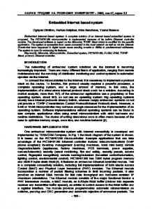
and assigned with a unique number. Whenever the car is stolen, the owner can make call, which triggers the inner system so that the car could not be moved further [9]. Vehicular identification and authentication of the driver based on zigbee also exist [10]. A system for authenticating driver and vehicle separately is designed by using individual smart card containing the user information and with digital certification (i.e) with LPR respectively. Whenever an event has been detected i.e. unlocking the car door alerts the owner of the car, once the car starts it helps the owner to track the vehicle through GPS (Global Positioning System) [11]. The owner can also stop the vehicle by sending a message to the GSM modem located inside the vehicle which ceases the engine [12]. Another technique is that the insertion of key is detected by the proximity sensors placed and asks the user to enter the password, if wrong password is entered for more than three trials a text message about the vehicle number and the location is sent to the cops along with another message intimating the owner about the car theft. It traps the unauthorized user inside the car by deactivating the fuel injector [13]. An entry card along with an in-built code in the vehicle replaces the key system with a keyless system [14]. Use of RFID tags [15] and smart cards [16] in Electronic toll collection (ETC) system makes the process simpler and easier .The deduction of amount is either from the user’s credit card [17] or prepaid card or from the user’s bank account [18]. The tollgate system is designed to automate the collection of charges for the vehicles and to keep track of them in the predestined routes with the help of the records collected [19]. RFIDSIM card based ETC system is also presented in expressway for payment system [20]. An LPR is one of the techniques, used in applications like electronic toll collection, traffic monitoring etc., in which the image of the vehicle is captured; the characters are extracted, isolated and identified [21] [22]. Even though there have been many different solutions proposed, there exist some drawbacks that only the particular person whose information has been stored in the database can access the vehicle. Captivating the advantages with the above workings, leaving the drawbacks out, a new solution is composed for anti theft scheme along with an effective toll collection system. III. PROPOSED SYSTEM The block diagram shown in Fig.1.depicts the hardware configuration of the proposed system. An enhanced design to the present security features used in vehicle system along with effective toll collection maintained and controlled by a main server is proposed.
Fig.1. Block diagram of the proposed system
ISSN : 0975-4024
Vol 5 No 1 Feb-Mar 2013
411
S. Dharanya et al. / International Journal of Engineering and Technology (IJET)
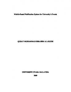
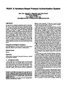
The entire system can be categorized into three units. 1. Vehicle unit 2. Main server unit 3. Tollgate/check post unit A. Vehicle Unit: An Anti-theft system for vehicles is constructed, which has bi-verification scheme so that the security level for vehicles can be highly increased. In each vehicle, an entity is present which consist of a PIC16F877A microcontroller interfaced with keypad along with LCD Display, a RFID reader, a unique code and a zigbee unit. The bi-Verification scheme has password verification process at its first level. The password entered by the object is compared with the database of the particular vehicle on the main server and the second level of verification is initiated once the first level verification is passed. The vehicle locks itself when the password was entered wrong for five times in a stretch. After authentication, the Person who drives the vehicle can now insert his/her RFID card (smart card driving License) into the slot. Now, the details sent by the microcontroller to the main server helps in verifying the driving license for expiry date, previous punishments, etc. Once passed, the object can now initiate the engine ignition. B. Server Unit: The server unit includes Access and Control unit, Zigbee and GSM. Zigbee receives the incoming information which is processed by the access and control unit. The server unit maintains separate databases for the vehicles and for the registered users. GSM modem sends the information as messages regarding the deduction of amount from their respective bank accounts. C. Toll Gate/Check Post Unit: This unit includes AT89S52 microcontroller, RFID reader, LED/Signal, and a LCD display. Whenever a vehicle crosses tollgate/check post, a reader placed on the trail reads the unique code of the vehicle and sends the information to the main server. The server checks with the unique code of the vehicle to find out the penalties for the current user and for the vehicle. There are four possibilities of penalty collection can occur which are listed below. CASE 1: Penalty for the vehicle and not for the one who drives it. CASE 2: Penalty for the user and not for the vehicle. CASE 3: Penalties for both vehicle and person who rides it. CASE 4: No penalties for both. Depending on the penalties for the vehicle and for the user, the amount is deducted along with the toll amount for the particular booth from the user’s account. D. Design Flow: Whenever the user enters into the vehicle, user must enter the password through the keypad. The information is sent to the Server unit through Zigbee to check whether the entered password is correct or not. Once the password is matched the notification/information about the vehicle will be sent to the user like Insurance expiring states (valid, about to expire, expired). If the password does not match, then the user would not get any notifications and he/she cannot start the car. Next level is the verification with Smart card driving license (instead RFID Tag used in this system), once the user enters the card, the controller will process it and sends the information to the main server where it can check whether he/she is a registered user or not. The information is sent back to the user whether the license card is valid or expired or going to expire, which will be shown in the LCD display. Once the Bi-verification level is complete, the penalty (if any) for the vehicle and also penalty (if any) for the chauffeur is listed in the main server. If the vehicle crosses any tollgate/check post the amount pertained to the vehicle owner and the chauffeur is deducted from their respective bank accounts and the information about the deduction of the amount is sent to them as a message through GSM Modem. The flow diagram in Fig.2.describes the entire flow of communication between the vehicle unit and the main server unit and Fig.3.shows the main server unit and tollgate/check post unit’s communication.
ISSN : 0975-4024
Vol 5 No 1 Feb-Mar 2013
412
S. Dharanya et al. / International Journal of Engineering and Technology (IJET)
Fig.2. Flowchart for vehicle unit along with main server
Fig.3. Flowchart for main server along with tollgate/check post unit
ISSN : 0975-4024
Vol 5 No 1 Feb-Mar 2013
413
S. Dharanya et al. / International Journal of Engineering and Technology (IJET)
IV. HARDWARE DESCRIPTION A. PIC16F877A Microcontroller: PIC 16F877A is a 40 pin PDIP 8 bit microcontroller with RISC (Reduced Instruction Set Computer) architecture is a cost effective and efficient for low end applications. It’s of 8K size of Program memory, 368 bytes of data memory and 256 bytes of EEPROM data memory. It has multi-functionality ports (PORTAPORTE), three 16-bit Timers/counters, one serial port,10 bit Multi channel ADC converter, operates with a frequency of 0-20MHz and power supply of 2.0-5V. B. AT89S52 Microcontroller: AT89S52 is also a 40 pin PDIP 8 bit microcontroller with CISC (Complex Instruction Set Computer) architecture. It has four ports PORT0-PORT3, three 16-bit timers/counters, one serial port, 64K bytes of external program (ROM) memory, 64K bytes of Data (RAM) memory, on chip oscillator and power supply of 2.0-5V which is flexible, cost effective and most suitable for many embedded applications. C. RFID Reader/RFID Tag: There are two different kinds of tags: Active and passive tags. The passive tags are used in this proposed system which is read wirelessly by the RFID reader. Its read frequency is 125 KHz and operates at 5V. Passive tags need no battery power but require power from the reader and it can be used for short range communication via electromagnetic induction. These kinds of tags are used for personal identification and tracking. When the tag comes under the magnetic field of RFID reader the tag gets energized by the induced current and sends the information stored on the chip. D. GSM Modem: GSM (Global System for Mobile communication) is a dedicated wireless modem which acts as a mobile phone. It requires a Subscriber Identity Module (SIM) card that sends and receives the information through radio waves. Wavecom Fastrack M1306B used in this system is a highly flexible plug and play GSM 900/1800 MHz modem which is easy to integrate with the system through serial connection (RS232). GSM modem supports a common set of standard AT Commands. Its operating voltage is 5V. E. Keypad/ LCD: Keypad and LCD (Liquid Crystal Display) are the most widely used input/output devices interfaced with the microcontroller placed inside the vehicle unit. The keys are arranged in a matrix form of rows and columns. 4X4 matrix keypad is connected to two ports. On a key press, a row and a column makes contact and get detected. 2x16 LCD display is a most popular and widely used output device than LED which has the capability to display characters, numbers etc. F. Zigbee: Zigbee CC2530 is based on 2.4 GHz IEEE 802.15.4 specification. It is a popular wireless connectivity due to its low cost, low data rate, low power consumption applications when compared to other wireless technologies like Bluetooth and Wi-Fi. Hence it is an effective and widely used in wireless communication technique. V. SOFTWARE DESCRIPTION A. MPLAB IDE: MPLABv8.63 IDE is an integrated tool runs on MS Windows for the development of embedded applications in PIC microcontrollers [23]. The code is written in C language in order to have a user-friendly operation and the Hi-Tech C compiler converts the high level code into a machine code [24]. The generated hex file is downloaded using PICkit2 programmer into the target controller [25]. Fig.4.shows the compilation screenshot.
Fig.4. Compilation screenshot using MPLAB software
ISSN : 0975-4024
Vol 5 No 1 Feb-Mar 2013
414
S. Dharanya et al. / International Journal of Engineering and Technology (IJET)
B. C SHARP: C# (pronounced as C sharp) language is proposed to be simple, robust, economical, Multiplatform support, general purpose language suitable for embedded applications ranging from dedicated functions to very large sophisticated systems. C# 3.0 Microsoft visual studio 2008 .NET Framework IDE is used in this application [26] [27]. The screenshot of C# is shown in Fig.5.
Fig.5.The Form design using C# is shown in Microsoft Visual Studio IDE
C. KEIL µVision 4: KEIL µVision IDE development tool is used to compile and debug the 8051 program written in C [28]. Its working process is simple and easy to use. It helps to develop the embedded programs rapidly. Once the target code is generated it is dumped using flash magic software [29]. The keil simulator screenshot is shown in Fig.6.
Fig.6.Keil simulator screenshot
VIII. RESULTS A. HARDWARE RESULTS: Snapshot of the vehicle unit is shown in Fig.7. Keypad and LCD are interfaced to the PORT B and PORT D of the PIC microcontroller respectively. Zigbee and RFID reader are connected serially to the PIC controller. Fig.8.shows the snapshot of the tollbooth unit. The RFID reader is serially connected to the AT89S52 controller to read the unique number of individual vehicles which passes by the tollgate/check post. Fig.9. shows the entire hardware setup of the proposed system which consists of vehicle unit, main server unit and the tollgate/check post unit.
ISSN : 0975-4024
Vol 5 No 1 Feb-Mar 2013
415
S. Dharanya et al. / International Journal of Engineering and Technology (IJET)
Fig.7.Snapshot of the vehicle unit
Fig.8. Snapshot of the tollbooth unit.
Fig.9. Entire hardware setup
Snapshots presented below shows the instructions for the user through LCD display. Fig.10.displays the two levels of verification that the chauffeur has to pass through. Fig.11.shows the different cases of License card verification like License card valid, license card expired and License card is going to expire.
Fig.10. LCD display shows the two levels of verification
ISSN : 0975-4024
Vol 5 No 1 Feb-Mar 2013
416
S. Dharanya et al. / International Journal of Engineering and Technology (IJET)
Fig.11.Snapshots for the different cases of license card verification
B. SOFWARE RESULTS: Fig.12.is the screenshots on the main server unit. Zigbee is serially interfaced to the PC through RS232 connector, which receives the information entered by the chauffeur. Fig.12.(a) shows the form design. Fig.12.(b) and (c) shows the checking of first level i.e. password (valid or invalid). Fig.12. (d), (e) and (f) shows the checking of second level i.e. license verification (valid, expired and going to expire) along with the penalties listed for both the chauffeur and the vehicle owner separately, the messages about the deduction of amount will be sent to both of their mobile phones through GSM modem which is connected to the PC through a serial to USB converter. Snapshot of messages delivered to the chauffeur and to the owner is shown in Fig.13.
(a)
ISSN : 0975-4024
Vol 5 No 1 Feb-Mar 2013
417
S. Dharanya et al. / International Journal of Engineering and Technology (IJET)
(b)
(c)
(d)
(e)
(f) Fig.12.Screenshots for the list view in C#
Fig.13. Messages delivered to the chauffeur and to the vehicle owner separately
ISSN : 0975-4024
Vol 5 No 1 Feb-Mar 2013
418
S. Dharanya et al. / International Journal of Engineering and Technology (IJET)
The amount is deducted from the chauffeur and vehicle owner’s account separately and they will be intimated about the exact charge and reason for amount deduction as a message through GSM modem. The various deduction methods on the tollgates are given along with its description in Table.1. Chauffeur
Vehicle
Description
0
0
Only toll amount is deducted
0
1
Penalty from vehicle owner +toll amount will be deducted
1
0
Penalty from chauffeur +toll amount will be deducted
1
1
Penalty from vehicle owner + chauffeur+ toll amount will be deducted
Where: 0-No fault, 1-Fault Table.1. Different cases in the tollgate/check post unit
IX. CONCLUSION AND FUTURE SCOPE The proposed work gives a unique way to protect vehicles along with an automatic toll collection that helps to regulate the process in an easy way. In an outlook, automated vehicle tracking and monitoring may be done with a GPS system for tracing the vehicle speed and giving automated warning when a vehicle reaches the speed limit and deducing the penalty directly if the object ignores the warning. Identifying the stolen car using GPS and controlling the car from remote using server can also be added. In addition to registering a bank account, a prepaid card can be allotted to each vehicle and object for those who don’t wish to register their bank accounts, so that the amount will be deducted from the card which should be recharged when there is not enough balance in the card. Displaying the sign boards on the roadside in the LCD may also be implemented. REFERENCES [1]
[2] [3] [4] [5]
[6] [7] [8] [9] [10]
[11] [12] [13] [14] [15] [16]
Nor Azlina , Bt Abd Rahman , Mohsen Bafandehkar, Behzad Nazarbakhsh , Nurul Haniza Bt Mohtar , “Ubiquitous Computing For Security Enhancement Of Vehicles”, IEEE International Conference on Vehicular Electronics and Safety (ICVES) ,Beijing, pp: 113118, 2011. Omidiora E.O, Fakolujo O.A, Arulogun O.T, Aborisade D.O, “A Prototype of a Fingerprint Based Ignition Systems in Vehicles”, European Journal of Scientific Research, pp: 164-171, 2011. Weiqi Yuan, Yonghua Tang, “The Driver Authentication Device Based on the Characteristics of Palm print and Palm Vein”, International Conference on Hand-Based Biometrics (ICHB), Hong kong, pp: 1-5, 2011. Hugo Silva, Andr’e Lourenc¸ O’Ana Fred, “In-Vehicle Driver Recognition Based on Hands ECG Signals”, International Conference on Intelligent User Interface , Lisbon, Portugal, pp: 25-28, 2012. Ronghua Chen, Mary Fenghua She, Xiangping Sun, Lingxue Kong, Yuchuan Wu , “Driver Recognition Based on Dynamic Handgrip Pattern on Steeling Wheel”, 12th ACIS International Conference on Software Engineering, Artificial Intelligence, Networking and Parallel/Distributed Computing, Sydney NSW, pp: 108-112, 2011. Pazhampilly Sreedevi A, Sarath S Nair B, “Image Processing Based Real Time Vehicle Theft Detection And Prevention System”, International Conference on Process Automation, Control and Computing (PACC), Coimbatore, pp: 1-6, 2011. Aditya I.V.N.S, Radha Krishna Murthy Y, Ravindra Babu Kallam Lt, “Alternate Method for the Failure of Antitheft Device used in Motor Vehicles”, International Journal of Computer Applications, Vol. 13, No.6, pp: 23-26, 2011. Bagavathy . P , Dhaya . R, Devakumar.R , “Real Time Car Theft Decline System Using Arm Processor”, Proceedings of International conference on Advances in Recent Technologies in Communication and Computing , 2011. Ali Rahnamei, Farnood Khoshnevis, Mina Vajdi, Payam Farhadi , “ A Design for CAR Anti-Theft System using Cell Phone”, International Journal Of Advanced Scientific Research And Technology, Vol. 1, No.2, pp: 1-5, 2012. Dissanayake S. D., Karunasekara P. P. C. R., Lakmanaarachchi D. D., Rathnayaka A. J. D., Samarasinghe A. T. L. K. ,“Zigbee Wireless Vehicular Identification and Authentication System”, 4th International Conference on Information and Automation for Sustainability, Colombo, pp: 257-260, 2008. Kunjal P. Tanna , Preeti Kumar, Shubha Narayanan, “Instant Theft Alert and Tracking System in Car”, International Journal of Computer Applications, Vol. 1, No. 21, pp: 29-34, 2010. Sangeetha.K , Arulraj.S , Aravind.G and Vignesh,M.M, “Intelligent Vehicle Theft Prevention And Location Finding System Using Face Detection Based On Image Processing”, International Journal of Communications and Engineering, Vol.1, No.1, pp: 1-6, 2012. Vinoth Kumar Sadagopan, Upendran Rajendran , Albert Joe Francis ,“Anti Theft Control System Design Using Embedded System”,IEEE International Conference on Vehicular Electronics and Safety (ICVES), Beijing, pp: 1-5, 2011. Motoki Hirano, Mikio Takeuchi, Takahisa Tomoda and Kim Ichiro nakano, “Keyless Entry System With Radio Card Transponder”,IEEE Transactions On Industrial Electronics, Vol. 35, No. 2, pp: 208-216, 1988. Elipe.NageswaraRao, Tirumala Vasu G, Prasad N.G.N., Kranthi Kumar, Rajesh V., “Payment Automation at Toll-Gate Using RFID and SMS Alert”, International Journal on Electronics & Communication Technology (IJECT), Vol. 2, pp: 109-113, 2011. Raadhikaa, “Electronic Toll Collection System”, Universal Journal of Applied computer Science and Technology(UNIASCIT) , pp: 58, 2011.
ISSN : 0975-4024
Vol 5 No 1 Feb-Mar 2013
419
S. Dharanya et al. / International Journal of Engineering and Technology (IJET)
[17] Atif Ali Khan, Adnan I. Elberjaoui Yakzan, Dr Maaruf Ali ,“Radio Frequency Identification (RFID) Based Toll Collection System”, Third International Conference on Computational Intelligence, Communication Systems and Networks, Bali Indonesia, pp: 103-107, 2011. [18] Khadijah kamarulazizi, Dr.Widad Ismail, “ Electronic Toll Collection System Using Passive RFID Technology”, Journal Of Theoretical And Applied Information Technology, vol.22, No2, pp: 70-76, 2010. [19] Yuhua Guo, Hong Li and Zhao Li, “The Application of RFID-SIM in Electronic Toll Collection System”, International Conference on Computational and Information Sciences, China, pp: 913-916, 2011. [20] Huang Wenjie , “Automatic Vehicle License Plate Recognition System Used in Expressway Toll Collection”, International Conference on Computer Science and Information Technology (ICCSIT), vol. 6, pp: 159-162, 2010. [21] Muhammad Sarfraz, Mohammed Jameel Ahmed, and Syed A. Ghazi, “Saudi Arabian License Plate Recognition System,” IEEE Proceedings of the International Conference on Geometric Modeling and Graphic, pp: 36-41, 2003. [22] Song Qing-kun, Yuan Hui-jun, Zhou Teng, “License Plate Recognition Based On Mathematical Morphology Method and RBF Neural Network”, Intemational Conference on Measurement, Information and Control (M1C), Harbin, pp: 782-786, 2012. [23] MPLAB IDE User’s Guide available online at http://ww1.microchip.com/downloads/en/devicedoc/51519a.pdf [24] PIC16F87XA Data Sheet available online at http://ww1.microchip.com/downloads/en/devicedoc/39582b.pdf [25] PIC kit2 Programmer information available online at http://www.nskelectronics.in/pickit2_programmer_to_go.html [26] Aboutc#:http://zeus.nyf.hu/~bajalinov/my_special/SW/C%23%203.0%20-%20The%20Complete%20Reference%20%20Herbert%20Schildt.pdf. [27] About C# tutorials:http://msdn.microsoft.com/en-us/library/618ayhy6(v=vs.71).aspx [28] AT89S52 Data Sheet available online at http://www.keil.com/dd/docs/datashts/atmel/at89s52_ds.pdf [29] KEIL µVision 4 User’s Guide available online http://www.keil.com/support/man/docs/uv4/uv4_overview.htm
ISSN : 0975-4024
Vol 5 No 1 Feb-Mar 2013
420