Appl. Math. Inf. Sci. 12, No. 2, 345-359 (2018)
345
Applied Mathematics & Information Sciences An International Journal http://dx.doi.org/10.18576/amis/120209
Embedded Real-Time Video Surveillance System based on Multi-Sensor and Visual Tracking Laith M. Fawzi1,∗ , Sideeq Y. Ameen2, Salih M. Alqaraawi3, and Shefa A Dawwd1 1 Department
of Computer Engineering, University of Mosul, Mosul, Iraq of Research and Graduate Studies, Applied Science University, Bahrain 3 Department of Computer Engineering, University of Technology, Baghdad, Iraq
2 Deanship
Received: 10 Dec. 2017, Revised: 12 Jan. 2018, Accepted: 17 Jan. 2018 Published online: 1 Mar. 2018
Abstract: This Paper describes the design and implementation of an embedded remote video surveillance system for general purposes security application. The proposed system is able to detect and report vandalism, tampering, and theft activities before they take place via SMS, Email or by a phone call. The system has been enriched with a vast range of sensors to increase its sensing capability of different types of attacks. Moreover, the proposed system has been enhanced by adding a visual verification technique to overcome false alarms generated by sensors, where a video camera is integrated within the system software to capture video footage, verify, and track the abnormal events taking into consideration bandwidth consumption and real-time processing. Finally, the system was implemented using SBC (Raspberry Pi) as a working platform supported by OpenCV and Python as a programming language. The results proved that the proposed system can achieve monitoring and reporting in real-time. Where the average processing time specified to complete all the required tasks for each frame (starting from video source to broadcasting stage) does not exceed 64%. Moreover, the proposed system achieved a reduction in the utilized data size as a result of using image processing algorithms, reaching an average of 91%, which decreased the amount of transferred data to an average of 13.4 Mbit/sec and increased the bandwidth efficiency to an average of 92%. Finally, this system is characterized by being flexible, portable, easy to install, expandable and cost-effective. Therefore, it can be considered as an efficient technology for different monitoring purposes. Keywords: Embedded system, multi-sensors, visual verification, remote monitoring, keyframe, subimage.
1 Introduction In recent years, there has been a great deal of interest in video surveillance systems to meet the requirements of different security aspects such as industrial controlling and monitoring, environmental monitoring, personal care and so on. They have contributed significantly to the reduction of crimes and the preservation of property. Starting from small offices to large factories, these systems became very necessary and important to satisfy the security aspects in various areas of life [1]. Video surveillance technology enables a single operator monitoring of various activities in a complex zone using a distribution of network video sensors (cameras). The goal of these systems is to collect and spread real-time information from the monitoring area to the observer person in order to improve the awareness against negative phenomena [2]. Moreover, the capturing, processing, and ∗ Corresponding
transmitting of video footage helps in the documentation process and decision making. Therefore, these systems can bring peace of mind and improve the management of organizations. Since video cameras became widely available in the market with different specifications and reasonable prices, surveillance systems became more popular [3]. Early surveillance systems were used to monitor large areas for security purposes. The video cameras were constantly in monitoring mode of the area of interest and the data streams were sent to the central station for further processing. In these systems, the energy, storage capacity, and bandwidth were not a real problem. Each camera has its own power supply and is connected to a server site via a wired link. However, these systems were not smart enough to detect any change by themselves [4]. At present, the researchers are continuously working towards a networked surveillance systems. The reason for this trend is the increasing
author e-mail: Laith
[email protected] c 2018 NSP
Natural Sciences Publishing Cor.
346
L. Fawzi et al.: Embedded real-time Video Surveillance System based...
number of accidents and instability in most parts of the world. By using several surveillance cameras, a huge amount of visual data is captured. These data require continuous monitoring and checking for the existence of intrusion or any abnormal events. Therefore, such system requires constant human wakefulness. However, humans have limited capacity to perform such tasks. Thus, this task may become very boring and prone to human error. In addition, the huge amount of video data that is obtained from the surveillance cameras consumes a wide range of bandwidth and storage capacity when it is transmitted [5,6,7]. Today, current studies focus on the embedded smart surveillance systems rather than traditional systems. Where these systems have the ability to process visual data locally, communicate with each other and with the server via wireless links; in addition to having more flexibility and scalability. However, the power consumption and bandwidth are critical constraints in these systems, as the nodes are powered by batteries and the data is sent over a limited wireless bandwidth. Therefore, processing data locally can reduce the amount of transmitted data that effectively uses the bandwidth of the system. Moreover, this reduction will minimize the energy consumption in communication [4,8,9,10,11,12, 13]. In this paper, a smart real-time video surveillance system is presented to enable the observers to monitor the safety of area of interest using a wide range of sensors supported by a visual surveillance camera to increase system accuracy, reliability, and performance with minimal usage of bandwidth, power, and storage capacity. In addition, the proposed system was armed by a stepper motor controller to increase system Field of View (FoV) and keep object tracking. This system is able to work under different operation modes (manual or automatic), mastered by a web server hosted on the surveillance node. The proposed system can ensure real event notification, via SMS, email, and phone call (ringing) to notify the persons in charge that a new event has occurred. Finally, the system was implemented using SBC (Raspberry Pi) and Arduino Mega as a working platform supported by OpenCV and Python as a programming language.
2 The Proposed Surveillance System Frameworks The proposed surveillance system is composed of two part: hardware and software. The hardware part contains a group of models used to implement the smart monitoring system. While the software part is responsible for initialization, video capturing, image processing, object tracking, notification, and video broadcasting. The observer can use a dedicated control room or any client terminal (computer or smart phone) to control the entire system.
c 2018 NSP
Natural Sciences Publishing Cor.
2.1 The Proposed System Hardware The proposed system hardware is composed of five categories: a processing and controlling unit, multi-sensor box, surveillance camera, system communication modules, and a power supply unit as shown in Figure 1.
Fig. 1: The Entire Proposed System Hardware.
2.1.1 Processing and Controlling Unit The processing and controlling unit runs a real-time video processing system which can be used for smart monitoring and surveillance applications. The unit was implemented using an ARM processor run on a 1GHz clock for processing with an Arduino Mega 2560 microcontroller. The ARM processor with communication facilities, power supply, and the memory are represented in the Raspberry Pi B+ (RPI). More details about the specifications of Raspberry Pi Model B+ are given in [14]. The Arduino Mega 2560 is a microcontroller board based on the ATmega2560. It supports the main processing and controlling unit through USB cable via a dedicated message format prepared for this purpose. The main task of the Arduino microcontroller is to control the camera movement in Pan, Tilt, Zoom, and Focus via stepper motor shield stack on the GPIO bus of the Arduino. More details about the Arduino Mega 2560 board specification are given elsewhere [15] 2.1.2 Multi-Sensor Box . In this work, a group of sensors is collected together via Arduino Mega 2560 board to form what are known as multi-sensor boxes. These boxes are distributed for
Appl. Math. Inf. Sci. 12, No. 2, 345-359 (2018) / www.naturalspublishing.com/Journals.asp
sensing any event that falls within the surveillance zone. The number of multi-sensor boxes and the method of distribution depends on the zone to be monitored, in addition to the required accuracy and the specification of sensors used. These boxes are communicating with the processing and controlling unit (Raspberry) via an Ethernet or Wi-Fi adapter. Therefore, two types of multi-sensor boxes are designed (PoE and near field Wi-Fi). Each box contains multi types of sensors to sense temperature, flame, motion, shock, and sound. Such diversity in sensors and method of connection gives the proposed surveillance system the ability and flexibility to monitor the area of interest against different intrusions. Figure 2 shows the proposed multi-sensor boxes.
Fig. 2: The Proposed Multi-Sensor Box, (a) POE Based, (b) WiFi Based.
2.1.3 Surveillance Camera The surveillance camera is used to capture video footage from the area of interest and verifies the availability of the event that detected via multi-sensor box. The camera is driven by stepper motor driver that make it capable of moving (-90 to +90) in Pan and (-15 to +55) in Tilt to keep object tracking via the Arduino SPI interface. Furthermore, a pair of DC Motor controllers have been used to control the zoom and the focus. The proposed video camera used in this project is a CamScan DSP 36x Color Video Camera with digital zoom, autofocus, and wide angle. For more details and specifications of this camera see [16].
347
2.1.4 System Communication Modules System communication modules deal with sensors, video camera, GPS system, Arduino microcontroller, headquarters, and observers via different types of connections methods, Wi-Fi, Ethernet, USB, and GSM networks. The Raspberry Pi B+ unit has several connection ports (USB, Ethernet, and GPIO), and the new version of Raspberry Pi 3 has a built-in Wi-Fi port also. These ports have been exploited to achieve the research objectives and meet the main requirements for controlling and managing the system. The functions of these ports are to communicate with:1.Video input capture card via a USB2 port. In this case a USB video capture card was used for the purpose of connecting the analog video camera to RPI via USB2 port, since the RPI does not has AV input. Choosing a capture device depends on the type of video format that wants to capture, frame rate, video editing, and OS support. For example, MPEG4 (sequence of JPEG), @25 fps, and Linux OS support. Moreover, the proposed system can support any digital camera (webcam) via RPI USB2 port directly. 2.Arduino Mega controller board via another USB2 port. Through this port and via shield stepper motor driver on Arduino Mega 2560, the system can control the Azimuth and Elevation of the camera in order to keep object tracking and put it always in the middle of the scene. The Arduino motor shield R3 can be used to control two 4 wire stepper motor (for Azimuth and Elevation control) or four 2 wire DC motor. Therefore, another DC motor driver (L298N) was used to adjust the camera zoom and focus. The L298N DC motor driver is connected with the Arduino Mega across pins 44, 45, 46, 47, 48, and 49. 3.GSM model via a GPIO pins numbers 1, 6, 8, and 10 (3.3V, GND, Tx, and Rx) respectively. The GSM is a specialized type of modem that accepts a SIM card, and works over a subscription to a mobile operator, just like a mobile phone. GSM modem allows the processing and controlling unit (Raspberry PI) to communicate over the mobile network via RPI serial port. In this work, the GSM modem is used to send the alert message (SMS), make a call, and transfer data though the GPRS to the group of persons in charge. In addition to make phone calls to verify that the warning is received. The GSM modem used is SIM800L, and for more details see [17]. 4.Wi-Fi router via an Ethernet port to achieve connection with multi-sensor boxes and the headquarters (control room) through a wire and wireless connection method. Wi-Fi is based on the 802.11 standards which is a set of standards for wireless communication technology created and developed by the Institute of Electrical and Electronics Engineers (IEEE). These standards are mainly used for implementing Wireless Local Area
c 2018 NSP
Natural Sciences Publishing Cor.
348
L. Fawzi et al.: Embedded real-time Video Surveillance System based...
Networks (WLAN) in the frequency bands of 2.4 GHz to 5 GHz. The most common protocols of 802.11 are those defined by 802.11a, 802.11b, 802.11g, and 802.11n. For more details see reference [18,19]. The latest release of the series IEEE 802.11 is 802.11n in 2009, which is characterized by increased throughput and range of wireless networks through the use of Multiple-Input-Multiple-Output (MIMO) antenna technology. In addition, it involves increasing the channel bandwidth from 20MHz to 40MHz. Therefore, it supports maximum Bandwidth, up to 300 Mbps [19]. Today, most high-rate wireless systems use MIMO technologies, including 802.11n, LTE and WiMAX [18]. In order to transfer the data gathered by the sensors and surveillance camera, several technologies can be used such as dedicated channels, ZigBee, LTE, Wi-Fi, and WiMAX. These technologies however need to take into consideration the main requirements, adequate bandwidth, and low cost. ZigBee was excluded due to low bandwidth and coverage range whereas LTE is also excluded due to high cost and low coverage area and dedicated channels was eliminated due to high cost despite being the best in terms of bandwidth. Therefore, the technology that considered in the research project requirements in terms of cost, coverage, and bandwidth is the common Wi-Fi. 5.GPS model via GPIO Arduino Mega 2560 board using pins numbers 18 (Tx), 19 (Rx), 5v, and GND. The Global Positioning System (GPS) is a navigation system based on GPS satellites that provide information on the Positioning, Navigating, and Timing (PNT) anywhere on Earth via four or more satellites located in the line of sight. The development of GPS has helped the advancement of many applications that affect many sides of the modern life. Where now, most electronic devices use GPS technology such as cars, watches, cell phones, ATM machines and so on [18]. In this work, the GPS modem is used to receive the satellites signals which represent the coordinates (latitudes, longitudes, and altitudes) and pass it to the Arduino microcontroller. This information is very useful for determining the time and site of the threat. In addition, the GPS clock signal is used to generate a synchronization among surveillance nodes; especially if more than one node has data to send simultaneously. The GPS type used in this work is GTPA013, it is installed inside the SWVSB and connected to the single board computer (Raspberry PI) through a microcontroller (Arduino Mega). For more information about the GPS module see [20].
Fig. 3: The Entire System Communication Modules.
2.1.5 Power Supply Unit The system has been equipped with an efficient power supply unit and battery to provide the required DC power to all system parts and its peripherals. However, when the main power is on, the battery can be charged within no more than 2 hours in the worst case; and can operate more than 8 hours in full load operation with absence of the main power. The output DC power is 12W with different output voltage levels (5 / 7.5 / 9 / 12) to support different peripherals. Figure 4 shows the power supply for the proposed system.
Fig. 4: System Power Supply.
2.2 The Main Proposed System Software Figure 3, illustrates the entire system communication modules.
c 2018 NSP
Natural Sciences Publishing Cor.
This section contains image processing stage and surveillance algorithms stage. The image processing stage
Appl. Math. Inf. Sci. 12, No. 2, 345-359 (2018) / www.naturalspublishing.com/Journals.asp
explains the image processing algorithms and techniques, which represent the main core of the proposed system, where the results of this stage affect the decision-making accuracy in the other stages. At this stage, a set of specialized algorithms and tools have been adopted to perform image processing tasks. OpenCV library has been selected to be the toolkit for developing this stage coupled with powerful programming languages (C++, Python, and Java), which they are suitable for Linux environment. The surveillance algorithms stage describes the techniques that used by the system to do its job. The required actions of this stage depend on the outputs of the image processing stage. This stage also represents the verification mechanism of the alerts, when the system is activated as result of a specific event detected by one of the sensors. Therefore, without image processing, the decisions may be inappropriate or wrong as a result of sensors false alarm. Figure 5 shows the sequence of image processing and surveillance algorithms stages for the proposed system.
Fig. 5: System Main Algorithm.
First the image processing algorithm stage is explained, then the surveillance algorithms stage is illustrated, as follow:
349
2.2.1 Image Processing Algorithm stage As illustrated in Figure 5, the main goal of image processing is to visually detect intrusion, extract the object, and specify the object boundaries. Therefore, to achieve this goal the following procedures must be performed: 1.Frame Buffer Initialization: Before starting the image processing, a frame buffer must be initialized to receive the source video stream via a USB video capture card. 2.Frame Enhancement: A set of operations that deal with image processing based on the changes in the scene of interest. These operations are an attempt to improve the properties of the images stored in the frame buffer by removing noise, isolating individual elements and joining disparate elements in an image [21]. The most basic morphological operations are erosion, dilation, opening, and closing. Some of these operations tends to remove some foreground pixels from the edges while the others, tend to enlarge the boundaries of foreground regions in an image. The resultant of image enhancement gives some information that can be used to identify the frame color range such as background color range, foreground color range, day and night. 3.Histogram Calculation: is a graphical representation of the frequency density of image pixel values. It is useful for identifying the distribution of pixels in an image. For an 8-bit grayscale image, there are 256 different possible intensities. Therefore, the histogram will graphically display 256 numbers showing the distribution of pixels among those grayscale values. To enhance the contrast of an image there are two methods applied to the histogram by this stage. The first one is called histogram stretching and the second one is called histogram equalization. Histogram stretching (often-called normalization) is a technique that attempts to increase the contrast in an image by stretching the range of intensity values. While histogram equalization is a technique for adjusting image intensities to enhance contrast [22]. These two methods are useful for increasing the target or background boundaries and the target or background area. 4.Background Cancellation: also known as background subtraction, is the main processing step in many vision-based applications. It aims to extract the foreground (intrusion object) from the background [23]. This is done by calculating the difference between the current frame and a reference frame (keyframe), after a stage of image preprocessing such as image de-noising and morphology process. Through this process, the target is designated. Therefore, background subtraction is a very important part in many computer vision application like surveillance, object detection and Tracking [24].
c 2018 NSP
Natural Sciences Publishing Cor.
350
L. Fawzi et al.: Embedded real-time Video Surveillance System based...
5.Target Extraction: Based on the results from the previous process where the background of the scene has been eliminated, the target extraction stage determines the boundaries of the intrusion object (target) in terms of contour(s) that can be used to figure out the target parameters: centre, width, and height.
2.2.2 Surveillance Algorithms Stage This stage contains a set of algorithms working together to achieve the objectives of the proposed system, these algorithms can be summarized as follows: 1.Alert Generation and Notification Algorithm After target information (centre, width, and height) was specified by image processing algorithms, the process of alert generation and notification is started. At the same meaning, the procedures of this stage begin when there is a target discovered in the previous stage (Image Processing Algorithm). In this stage the video broadcasting stage is in progress. Therefore, these procedures require initialized a centralized computer placed in the Headquarters (HQ) with a specific IP address for security and optimization purposes (where two or more users simultaneously access the system configuration). Through this computer, the system will be controlled remotely, such as the system setup and surveillance modes selection (Manually, Patrol and Sensor Event). In addition, the system is capable of reporting the existence of an event (hazard) by sending SMS, Email, and even a phone call to the HQ and the group of persons in charge. As illustrated in Figure 6, the alert generation and notification stage includes the following: i.Getting the HQ Address: To get the information needed by the system (SWVSB) in order to communicate with HQ such as the website (URL), Email address and phone number. Such procedures are done in the System Setup stage. ii.Get the address of person in-charge: This step is used to get the information that the system needs in order to warn persons in-charge like Email address and phone numbers. Persons in-charge are the people who have the ability to make decisions or direct technical or security teams remotely. iii.Stream Broadcasting: This is done after the detection of a new event and verification of the presence of an intrusion by multi-sensor boxes supported by the image processing techniques that were carried out in the previous stages. The video broadcasting stage is started via web hosting. iv.Alert Message construction: At this stage, the alarm messages are built and configured to send in the format of SMS and Email form.
c 2018 NSP
Natural Sciences Publishing Cor.
Fig. 6: Alert Generation and Notification Algorithm.
v.Alert Notification: This stage is synchronized with the video broadcasting stage. Through this stage, the notifications are sent via SMS and Email. In addition to making a phone call. The phone call is used for alert verification purposes only. Once a connection is established, the call is terminated. This process can be repeated more than once. After that, the system waits for ACK in order to disable the alert. 2. Detection and Tracking Algorithm A set of actions must be taken for the purpose of target detection and tracking. These actions are done after frames gathering process. Some of these actions relate to image processing, like image enhancement, histogram calculation, frame subtraction, and finding contours, etc. other actions include video capturing, tracking window, servo system, stream construction, broadcasting, and sending alert notifications. The
Appl. Math. Inf. Sci. 12, No. 2, 345-359 (2018) / www.naturalspublishing.com/Journals.asp
tracking process is divided into two stages (tracking window and servo system control). The first stage is concerned with the window that identifies the moving object. On the other hand, the second stage is concerned with the servo system, which is responsible for controlling the camera movement (Azimuth/Elevation and Zoom/Focus) to ensure good tracking. Figure 7 shows the actions of the target detection and tracking process for the proposed system which include:
Fig. 7: Target Detection and Tracking Algorithm.
i.Color Conversion: The captured frames are in RGB format; these take a long time to process and lots of memory for buffering in the various stages of image processing, target detection, and tracking. Therefore, there is a need to convert this format to a grayscale format. This procedure will facilitate and accelerate the arithmetic operations for image processing. Where it will be dealing with one color component (intensity) instead of three components (RGB). Therefore, it takes less computational time. ii.The Image Processing Part of the Tracking Process:
351
a.If the received frame is a keyframe then: •.Enhance the frame by applying some image processing tools (mask filter) such as erode and dilate. •.Subtract the current keyframe from the previous keyframe to produce the keymask. The keymask represents the template (mask) in bi-color to indicate the target region with white and background with black to facilitate the in scene target search algorithm. The frame will be scanned from four directions to determine the margin of the target and to calculate the centroid. This process is done once every second. b.Otherwise (not keyframe): •.Calculate the histogram (stretching, equalization). •.Do thresholding and segmentation: thresholding is the simplest method of image segmentation. From a grayscale image, thresholding can be used to create binary images. While, image segmentation is the process of partitioning a digital image into multiple segments. It is used to locate objects and boundaries in an image. •.Generate a new mask (binary image): a binary image is a digital image that consists of two colors, typically black and white. The color used for the object is the foreground color while the rest of the image is the background color. The generated new mask is more recently updated than the keymask. Because the new mask is calculated for each frame every 40 msec while the keymask is calculated every one second. •.New mask enhancement: the purpose of image enhancement is to clarify the resultant image (new mask) and remove appendages by applying erode and dilate mask filters. iii.Tracking Process: the process of comparing the new mask with the key mask, leads to the extraction of the target contour. Where, the contour is used to calculate the target coordinates (centre, width, and height). After that, the target tracking stage is initiated by drawing a quadrilateral shape surrounding the target (tracking window). This window follows up the target’s movements and has the same target centre. Simultaneously, the servo system controller is continuously updated with the new target coordinates in order to control the camera movement toward the target and to keep the tracking window in the middle of the monitoring screen periodically. The servo system is responsible for the overall camera movement to ensure good tracking and to keep the tracked object within the camera’s Field of View (FoV). The stepper motor driver is responsible for the Azimuth and Elevation control directions. The DC motor driver is responsible for adjusting the zoom level and focusing control. Continuous correction of coordinates and periodic updating of servo
c 2018 NSP
Natural Sciences Publishing Cor.
352
L. Fawzi et al.: Embedded real-time Video Surveillance System based...
direction will keep the target (intruder) within the tracking zone. Therefore, a series of processes must be applied by each frame time. Figure 8 illustrates the procedures of the servo system control stage.
Fig. 8: Servo System Control Algorithm.
These processes can be summarized as: a.Calculating the new location for the tracking window (center, width, and height), which is calculated for each frame during the image processing stage (finding the target contours). b.Updating the servo system with the new information (Azimuth/Elevation and Zoom/Focus) and taking into consideration the previous values stored in the accumulated buffer. The accumulated buffer always retains the last ten readings and calculates their average (Moving Window Averaging Filter). This procedure helps to make the camera smooth when it moves (without hops). c.Calculating the error rate by finding the difference between the azimuth/elevation’s desired angles and azimuth/elevation’s actual angles. d.Correcting the coordinates according to the resulting error rate and the previous value in the
c 2018 NSP
Natural Sciences Publishing Cor.
accumulated buffer. Consequently, this procedure is necessary to avoid the accumulation of error. Then, the correction values are returned to the accumulator as a feedback before checking the window position again. 3.Stream Construction and Video Broadcasting Algorithms In this stage, the video stream construction process is started. This process includes the construction of a new video stream composed of a sequence of frames started by a (Keyframe) with a fixed size of (640 x 480) pixels, and 24 sub-frames (sub-images) that contain only the target (intruder), with an average size (no more than 20% of the full frame size). 1 keyframe and 24 sub-frames will be constructed using the JPEG encoding technique in order to build the video stream packet and prepare it for the broadcasting stage. Note that, each header of the constructed sub-frames contains the target image specifications, including the target image’s coordinates which are overlaid on the keyframe in their specific location. Then, the video stream will be broadcast on the website via the web host (Apache web server). Based on the results from the previous stages (motion detection and tracking), or upon the system setup and/or operator request; the process of video broadcasting is started. In other words, the broadcasting stage begins when the system detects an intrusion event or an operator initiates a new monitoring task (scheduled patrol or online monitoring). This process requires the preparation of a video stream buffer that collects frames (1keyframe + 24sub-images for each second). Where, on each keyframe, the key buffer will be erased from the previously overlapped frames and prepare to be ready for MPEG4 encoding techniques. While each sub-frame (sub-image) contains the target information only; the sub-image frame is encoded and the frame header is created with the MPEG4 encoder. Moving Picture Experts Group (MPEG4) is a standard for encoding moving pictures. It describes a set of video/audio lossy compression methods, which allow the storage and transfer of movies using the available media storage and transmission bandwidth [25]. After that, the generated packets from the encoding process are collected and compressed to be ready for sending via Ethernet. When the packets arrive at the destination, the client’s browser extracts the received packets (1keyframe + 24sub-images) and the system readout (sensors, system status), updates the HTML response to its request time. The display process takes place by caching the keyframe and overlaying each sub-image in its location on the keyframe. Figure 9 shows the process of video broadcasting for the proposed system and Figure 10 illustrate the broadcasting mechanism used in the proposed system (1keyframe and 24sub-images). The web server deploys a video broadcasting that supports the
Appl. Math. Inf. Sci. 12, No. 2, 345-359 (2018) / www.naturalspublishing.com/Journals.asp
353
MPEG4/JPEG streaming with some pivot characteristics that will enrich the display by offering stream cache and frame overlay features.
Fig. 10: The Broadcasting Mechanism .
or as a lightweight web server for a distinct website. Figure 11 shows the process of web hosting and management stage.
Fig. 9: Video Broadcasting Algorithm.
4.Web Hosting The availability of web browsers on various types of platforms (Computers, Mobile phones, and tablets) armed with several types of operating systems and processing power, encourages toward adopting the web solution as a GUI for mastering the SWVSB. The Raspberry PI B+ with its ARM processor is capable of hosting a dedicated web server for such a task and can serve as a monitoring and video streaming server in real time. Therefore, a lightweight version of Apache web server (Light http) is used to exploit its capabilities. This version provides a way of setting up a web server without putting too much load on the limited processing capability. It is ideal for providing web access to the Raspberry Pi as a monitoring tool,
Fig. 11: Web Hosting and Management Stage.
As illustrated in Figure 11, the Apache web server is an automated software that serves content in response to requests. The proposed system is managed through web application written in python language. Where, the Python is a powerful scripting language suitable for the smallest prototyping and largest projects. The idea behind the establishment of Python web application is that the Python code can be used for determining the content that is shown to the user and what action to take. In fact, this code (Python) runs via a web server that hosts the website, therefore the user can use the application without installing anything except the browser [26]. The Python Web Application deals with the system interface (multi-sensor box, surveillance camera, and servo
c 2018 NSP
Natural Sciences Publishing Cor.
354
L. Fawzi et al.: Embedded real-time Video Surveillance System based...
system) and other procedures that include, image processing, the detection and tracking process, stream construction, alert generation, and video broadcasting from one side and HTML rendering from another side. Where, HTML rendering is the process of displaying the requested content on the browser screen. Then, the host forwards the request to the server software (Apache) via a specified port and waits for the client’s ACK (confirmation) in order to turn off the processes. Finally, the proposed system runs across the system interface (web page). The observer can use any web browser to display the system web page (http://SWVSB.box) via any terminal or smart phone. The system web page has a friendly Graphical User Interface (GUI) hosted on Raspberry Pi as a web server. Through this interface, the system is managed and watched operating statuses such as system parameters info (power supply status, LAN status, Wi-Fi status, and GPS status), video streaming display and control info (display the broadcasting video, alert status, date, time, control the camera movement in manual/patrol mode, and reset the alert), remote multi-sensor box info (sensors status of POE and Wi-Fi multi-sensor box), GSM network info (GSM status, phone numbers, and message status), and system setup. The system setup web page is used to determined sensors setting (on/off), determined the persons in-charge numbers, set the appropriate warning messages, set network settings, and display the sensors log information. Figure 12 shows the proposed SWVSB web page system interface, while Figure 13 shows the setup web page of the proposed system.
Fig. 12: The Proposed System Web Page Interface.
5.System Status Update Algorithm The proposed system deals with two types of users, HQ and persons in-charge, to administrate the system and take the necessary actions. HQ is an authorized user that is able to access the system setup through the system homepage via a specific IP address and make
c 2018 NSP
Natural Sciences Publishing Cor.
Fig. 13: The Proposed Setup Web Page.
the required modifications (select monitoring modes, on/off sensors, and ACK). The person in-charge is the user that receives the alert messages and reporting. Note that, the authorization to access the system setup can be given to this user (person in-charge). Therefore, the system must respond to these orders and update the system status. The System status can be grouped into five categories: a.System Parameters: updating the system status parameters (power supply, security, and network status) will keep the system from any faults. Therefore, updating the system settings will helps to keep the system in an up-to-date state. b.Video Streaming and Control: in any mode of operation (Manual, patrol and sensor event), the video stream will be initiated to alert the observer about the new situation in the area of interest. c.Remote Multi-Sensor Box: by exploiting the information of the multi-sensor boxes to estimate the in-field environmental conditions and update the sensors readout on the website. d.GSM Network: updating the GSM network status for the network connection monitoring with GSM service provider. e.System Setup: updating the system setup web page makes the observer able to review the sensor’s readout and changes the system settings. These five categories will be updated in the form of Request/Response protocols and system event/acknowledgment across the web server and web applications to update the HTML page. Figure 14 illustrates the mechanism of system status updating for the proposed system. Finally, Figure 15 (a and b) shows the overall system design. The proposed system is protected by a shield box type IP65 with the dimensions of 300x400x165 mm; so the all electronic component is protected against various environmental conditions such as water, dust, and humidity. Moreover, the tampering and sudden shocks.
Appl. Math. Inf. Sci. 12, No. 2, 345-359 (2018) / www.naturalspublishing.com/Journals.asp
Fig. 14: System Status Update Algorithm.
355
Fig. 15: The Proposed Overall System Design; (a) The Proposed SWVSB Main Components, (b) The Proposed System Design After Packing.
3 Proposed System Hardware and Software Achieved Features The designed and implemented of the proposed system hardware and software achieved the following features:1.It is embedded real-time video surveillance system. 2.The process to control the SWVSB, POE sensors box, and Wi-Fi sensors box are done remotely through a wireless network and web interface (simple GUI) works via any web browser without extra software or a dedicated control room. Which make the system easy (friendly) to use, and easy to configure (setup, management). 3.Set of sensors integrated with video camera provide high accuracy to detect intrusion which result in decreasing the false alarms and gives true alert. Therefore, the proposed system can help minimize human errors, and assist in avoiding serious accidents. 4.The proposed surveillance system can be designed and implemented using multiple types of video cameras such as CCTV, IP, and webcam. 5.The camera Pan in Azimuth is about (-90 to +90) and the camera Tilt in Elevation is about (-15 to + 55 ). This design enable the system to track the event with wide angle.
6.The smartness and flexibility of the system lead to detect and track unwanted events within the area of interest using three surveillance modes (Manual, Patrol, and Sensors Events). 7.The system can be easily installed (not complicated), cost effective (low cost), and resistant to environmental hazard. The RPI can work in harsh environment with fan-less CPU. These features help the system to be spread in order to monitor large area. 8.Efficient video transmission with frame characteristics reduction and SWVSB synchronization help the system to maintain the available bandwidth. Since the proposed system takes into account the bandwidth consumption for each surveillance node. Therefore, replicating nodes to cover a large monitoring zone is one of the priorities of the system. 9.Standard video stream broadcasting for more viewer compatibility, hence MPEG 4 encoding is used as video format. 10.Reliable notifications (SMS, ringing, Email and captured video stream). 11.Smart power consumption because the system is wake on alert.
c 2018 NSP
Natural Sciences Publishing Cor.
356
L. Fawzi et al.: Embedded real-time Video Surveillance System based...
12.The proposed system has reasonable dimensions (300 x 400 x 165 mm) and Lightweight (1.5 Kg). Therefore, it can be placed on any column simply.
4 Result and Discussion In this section, the performance evaluation of the proposed system algorithms is presented in this section in order to show the advantages of the proposed system and the efficiency of the algorithms used. These results are divided into four categories: frame size comparison (received and sent), bandwidth utilization, bandwidth efficiency, and system processing time.
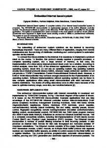
4.1 Frame size comparison The source data size (captured) is compared to the output data size (sent) as shown in Figure 16. As illustrated in
Fig. 17: Bandwidth Allocation Comparison.
for the proposed system is shown in Figure 17. Figure 17, illustrate the amount of bandwidth consumed when transmitted full frames colored without the processing techniques and output frames for the proposed system. Where the full frames consumed about 175 Mbit/sec while the output frames consumed about an average of 13 Mbit/sec. Since the proposed system sends the first frame (keyframe) as a full frame with 640 x 480 pixels every second. While the remaining 24 frames are sent as subimages with variable frame sizes based on intruder size.
4.3 Bandwidth efficiency
Fig. 16: Frame Size Comparison.
Figure 16, the average JPEG frames size is about 95 KB for the source frames, while the average JPEG output frames size is about 8 KB. The frame size reduction in the output frames of the proposed system is due to they contain subimages that hold only the target (intruder) which is truncated from the full frame (source) based on the use of image processing and object detection techniques. In addition, the output JPEG frames provide about average 91% of the data size compared to the source frames. Moreover, the source JPEG frames consumed about 122 MB of storage capacity on disk without image processing, while the proposed system consumes about 25.9 MB of storage capacity. However, Figure 16 illustrates the reduction in size between the source frames and output frames.
4.2 Bandwidth utilization The bandwidth allocation comparison between the broadcasting of full frames and output frames (subimage)
c 2018 NSP
Natural Sciences Publishing Cor.
The bandwidth efficiency indicates how efficiently the available bandwidth is utilized. Figure 18 illustrates the bandwidth efficiency delineation of the proposed system with respect to the conventional systems (without processing). It is clear from Figure 18, that the stream
Fig. 18: Bandwidth Efficiency Comparison.
bandwidth efficiency of the proposed system, reaches on average 92% when sending 24 variably sized frames (subimages) + 1 keyframe every second. Where the zigzag represents the efficiency of the subimages
Appl. Math. Inf. Sci. 12, No. 2, 345-359 (2018) / www.naturalspublishing.com/Journals.asp
transmission, while the decline pulses represent the transmission efficiency of the keyframes. This decline occurs once every second as a result of sending keyframes without processing.
4.4 System Processing Time This paragraph illustrates the processing time for each task and the responsiveness of the proposed system to work in real-time as shown in Figure 19. The figure
Fig. 19: System Processing Time.
shows the percentage image processing time per task per second of the proposed system. It is noted that the time taken by the proposed system to process the data received (according to algorithms used), does not exceed (68%) the time specified to complete all the task assigned to the system in the worst case as shown in the top curve (broadcasting). This means that the system can operate with real-time capabilities. In the same manner Table 1 shows the minimum and maximum time spent by each task individually.
Table 1: Min and Max Task Processing Time. Task Name Min-Max Task Time in (ms) Source (input) 1-4 Grayscale 2-3 Histogram 4-5 Mask 2 Target 6-9 Frame 1-3 Stream 1-3 Broadcasting 2-3
This table contains the minimum and maximum time required by each task. If the maximum time is considered, then the system needs 32 msec in the worst case to finish all the image processing and broadcasting tasks. This also confirms that the proposed system works in real-time.
357
5 Conclusion This paper presents the design and implementation of a smart embedded surveillance system capable of detecting, identifying, tracking and recording unwanted events within the area of interest in real-time, under low computing resources constraints. The system is able to verify the alerts coming from multi-sensor box visually before sending the alert messages and broadcast video with less bandwidth consumption. Consequently, this will increase the system’s efficiency, reliability, accuracy, and elimination of false alarms. It was also noted that the system that is designed achieves a reduction in storage capacity (on disk) to an average of 78% compared to the source data size without processing. In addition, the system processing time did not exceed the time specified for each frame (40 msec) from the video source to the broadcasting process. Therefore, the system maintained the work within real-time at all stages. Finally, this system is characterized by being flexible, portable, easy to install, expandable and cost-effective. Therefore, it can be considered as an efficient technology that used in different monitoring purposes like border areas, ports, government buildings, and important facilities. For the future works, the work can be extended by adding a central server with a database management system for data logging, updating, and analyzing. Where the database management system enables the data coming from multi-sensor boxes to be stored and query them by the client to improve the alertness of the decision making criteria. Moreover, improving the entire system performance through a mechanism that uses Cloud-managed and Internet of Things (IoT) for simplified the remote monitoring processes can also be carried out.
References [1] Solanki, K., Chaudhary, B. & Durvesh, A. Wireless Real Time Video Surveillance System Based On Embedded Web Server and ARM9. Int. J. Adv. Res. Eng. Technol. 2, 19-23 (2014). [2] Robert, C. et al. A System for Video Surveillance and Monitoring. (2000). [3] Mandrupkar, T., Kumari, M. & Mane, R. Smart Video Security Surveillance with Mobile Remote Control. Int. J. Adv. Res. Comput. Sci. Softw. Eng. 3, 352-356 (2013). [4] Imran, M. Investigation of Architectures for Wireless Visual Sensor Nodes. (Licentiate Thesis, Mid Sweden University, 2011). [5] Chen, W., Shih, C.-C. & Hwang, L.-J. The Development and Applications of the Remote Real-Time Video Surveillance System. Tamkang J. Sci. Eng. 13, 215-225 (2010). [6] Martinel, N. On a distributed video surveillance system to track persons in camera networks. Published by Computer Vision Center / Universitat Aut ‘onoma de Barcelona, Barcelona, Spain 14, (PhD. Thesis, University of Udine, 2015). [7] Sutor, S. Large-scale high-performance video surveillance. (PhD. Thesis, University of Oulu, Faculty of Information Technology and Electrical Engineering, 2014).
c 2018 NSP
Natural Sciences Publishing Cor.
358
L. Fawzi et al.: Embedded real-time Video Surveillance System based...
[8] Patel, P. B., Choksi, V. M., Jadhav, S. & Potdar, M. B. Smart Motion Detection System using Raspberry Pi. Int. J. Appl. Inf. Syst. 10, 37-40 (2016). [9] Sumalatha, G. & Bharathiraja, S. Implementation of Real Time Video Streamer System in Cloud. Int. J. Eng. Appl. Sci. 3, 67-70 (2016). [10] Vaidya, R. R. Efficient Embedded Surveillance System With Auto Image Capturing and Email Sending Facility. Int. J. Tech. Res. Appl. 3, 109-112 (2015). [11] Arathi, K. & Pillai, A. Low-Power Home Embedded Surveillance System Using Image Processing Techniques. in ICAIECES, 377-389 (Springer, New Delhi, 2016). [12] Myrala, N. & Vijaya, K. AUTOMATIC SURVEILLANCE SYSTEM USING RASPBERRY PI AND ARDUINO. IJESRT 3, 635-640 (2017). [13] Gervacio, M., Esteves, A., Tamondong, R. & Faustino, X. GSM Based Home Embedded Surveillance System Utilizing Pyroelectric Infrared Sensor. in Cebu International Conference on Computers, Electrical and Electronics Engineering 144-147 (Technological Institute of the Philippines, Philippines., 2017). [14] Raspberry Pi. Raspberry pi foundation Available at: https://www.raspberrypi.org/products/. [15] Arduino. Arduino Mega 2560. (2017). Available at: https://www.arduino.cc/en/Main/arduinoBoardMega. [16] CamScan. Security Surveillance Solutions. 1-102 (2012). Available at: http://www.camscan.ca/product download.php?filename= CAMSCAN Product Catalogue - 2015 27MB.pdf. [17] SIMCom. SIM800L Hardware Design V1.00. 1-70 (2013). doi:SIM800L Hardware Design V1.00 [18] Lereno, G. Raspberry Drone: Unmanned Aerial Vehicle ( UAV ). (MSc. Thesis, Technical University of Lisbon, 2015). [19] Abdelrahman, R., Mustafa, A. & Osman, A. A Comparison between IEEE 802.11a, b, g, n and ac Standards. IOSR J. Comput. Eng. Ver. III 17, 26-29 (2015). [20] Lady, A. Adafruit Ultimate GPS. Adafruit Industries 1-38 (2017). Available at: https://cdnlearn.adafruit.com/downloads/pdf/adafruit-ultimate-gps.pdf. [21] OpenCV. OpenCV 2.4.13.2 documentation. OpenCV Dev Team (2014). Available at: http://docs.opencv.org/2.4/genindex.html. [22] Tutorialspoint. Digital Image Processing. (2017). Available at: http://www.tutorialspoint.com/dip/. [23] Doxygen. Background Subtraction. OpenCV (2017). Available at: http://docs.opencv.org/trunk/db/d5c/tutorial py bg subtraction.html.
[24] Manikandan, R. & Ramakrishnan, R. Human Object Detection and Tracking using Background Subtraction for Sports Applications. Int. J. Adv. Res. Comput. Commun. Eng. 2, 4077-4080 (2013). [25] Rump, N. MPEG-2 Video. MPEG-2 Copyright Identifier (2006). Available at: http://mpeg.chiariglione.org/standards/mpeg-2/video. [26] Kenneth Reitz. Web Applications & Frameworks. (2016). Available at: http://docs.pythonguide.org/en/latest/scenarios/web/. [27] C. Bianca and L. Fermo, Computers & Mathematics with Applications 61, 277-288 (2011).
c 2018 NSP
Natural Sciences Publishing Cor.
Laith M. Fawzi received the B.Sc. degree in Electrical and Computer Engineering from Military Engineering College, Iraq, in 1999; and the M.Sc. degree in Computer Engineering from University of Technology, Iraq, in 2005. He worked as a lecturer in Al-Rafidain University College in Iraq until 2011, in addition to his work in the Ministry of Science and Technology (MOST), Iraq till now. His researches interest in the area of networks design. He has an experience in networking, communication and information technology (IT). Siddeeq Y. Ameen received BSc in Electrical and Electronics Engineering in 1983 from University of Technology, Baghdad. Next, he was awarded the MSc and PhD degree from Loughborough University, UK, respectively in 1986 and 1990 in the field of Digital Communication Systems and Data Communication. From 1990 - 2006, Professor Siddeeq worked with the University of Technology in Baghdad with participation in most of Baghdad’s universities. From Feb. 2006 to July 2011 he was a Dean of Engineering College at the Gulf University in Bahrain. From Oct. 2011 - Sep. 2015 he joined University of Mosul, College of Electronic Engineering a Professor of Data Communication. From Sep. 2015, he Through his academic life he published over 100 papers and a patent in the field of data communication, computer networking and information security and supervised over 100 PhD and MSc research students. He won the first and second best research in Information Security by the Arab Universities Association in 2003. Finally, from Sep. 2015 - Sep. 2017, he served as a Dean of research and graduate studies at Applied Science University in Bahrain and awarded the Higher Education Academy Fellowship.
Appl. Math. Inf. Sci. 12, No. 2, 345-359 (2018) / www.naturalspublishing.com/Journals.asp
Salih M. Al-Qaraawi rreceived the B.Sc. degree in Electrical and Electronics Engineering from the University of Technology, Baghdad, in 1977. Next, he was awarded the M.Sc. degree in Computer Engineering in 1980 from Control and Systems Engineering, University of Technology, Baghdad then Ph.D. degree in Computer Engineering in 1994 from University of Technology, Gdansk, Poland in the field of Fault Diagnosis and Reliability of computer networks. Professor Salih worked in University of Technology, Baghdad since April 1983- present. He was Dean Assist of Control and Systems Engineering from 1996-2003 and 2006-2012 then the Dean of Computer Engineering, University of Technology since 2013 - present. He published about 30 papers in the field of computer networks, reliability, microcontroller’s applications, and data communication and network security. He supervised over 10 Ph.D. and 33 M.Sc. students.
359
Shefa A. Dawwd received the B.Sc. degree in Electronic and Communication Engineering, the M.Sc. and the Ph.D. degree in Computer Engineering in 1991, 2000, and 2006, respectively. He is presently a faculty member (Associate Professor) in the Computer Engineering Department / University of Mosul. His main research interests include image & signal processing and their hardware models, parallel computer architecture, hardware implementation and GPU based systems. He has authored more than 29 research papers. He has been an editorial member of several national and international journals.
c 2018 NSP
Natural Sciences Publishing Cor.