Sixth Engineering, Science and Technology Conference “Tendencies and Challenges in Engineering, Science and Technology” (ESTEC 2017) October 11 - 13, 2017 Panama City, Panama.
Embedded system generating trajectories of a robot manipulator of five degrees of freedom (D.O.F). Jorge Luis Aroca Trujillo
Corporación Universitaria del Huila, Neiva, Republica de Colombia,
[email protected]
Jorge Bernardo Ramírez Zarta
Corporación Universitaria del Huila, Neiva, Republica de Colombia,
[email protected]
Ruthber Rodríguez Serrezuela
Corporación Universitaria del Huila, Neiva, Republica de Colombia,
[email protected]
ABSTRACT
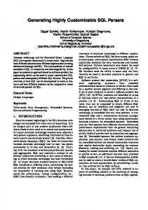
The main principal of the interaction of the robot with work environments is to position the coordinate system of the final effector in a desired orientation and position. To do this, algorithms must be used to generate and control the coordinated movements of the robot joints. This article will deal with three movements (MOVEJ, MOVES and MOVEC) implemented in the industrial controller CompactRIO, which can be combined so that the robot can develop any task that is scheduled. Keywords: DKM, IKM, CompactRIO, Slerp. 1. INTRODUCTION This work presents three types of algorithms that generates trajectories that provides the positions that must be followed by a manipulator robot of Five Degrees of Freedom (5D.O.F.) [Kazemi et al., 2016], to execute a specific task. The first algorithm develops a joint path (MOVEJ), which has no relevance to the path that the end effector makes. The other two will generate Cartesian trajectories that will draw with the end effector the shape of a line or an arc (MOVES and MOVEC). These algorithms will be implemented in a generic industrial controller (CompactRio, figure 1), that is, a controller different from those designed to operate commercial manipulator robots. It will interact with the user through a computer connected remotely by the Ethernet port. Programming was implemented through LabView, which facilitates visualization, creation and modification of tasks that the user would like the manipulator to replicate. The developed interface will contain the reading of the commands, the mathematical modeling found, the algorithms for generating trajectories, the visualization of variables and the position control (PID) for engines [Deshpande et al., 2012], this will be programmed in the chassis of the controller.
Panama City, Panama
6th Engineering, Science and Technology Conference (ESTEC 2017) October 11-13, 2017
1
Figure 1: Industrial Controller - NI CompactRIO, [Retrieved on June 8, 2017 from: http://www.ni.com/compactrio/value-controller/esa/]. Having programmed the path generator algorithms and the position control system in the CompactRIO controller allows the manipulator to continue the task it is developing when there is a connection failure between the computer and the controller. In this way, there will be an interconnection between the robot manipulator, the industrial controller CompactRIO and the computer designated to modify and visualize the variables present to generate and control the positions and trajectories that the manipulator needs to generate a task. 2. DESCRIPTION OF THE ALGORITHMS OF IMPLEMENTED TRAJECTORIES Three movements (MOVEJ, MOVES and MOVEC) will be dealt with, which will be implemented in the industrial controller CompactRIO [Alcaraz, 2012], [Parra, 2015], supported in new contributions in the mathematical part [Zarta et al., 2016, 2017], [Serrezuela et al., 2016, 2017], which can be combined so that the robot can carry out a specific task.
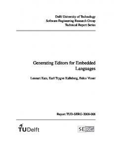
a) Joint motion.
b) Linear motion.
c) Arch motion.
Figure 2: Simulation of joint movement.
2.1 JOINT MOTION: MOVEJ The use of this movement allows the manipulator to reach an end position, with independent joint movements. This does not ensure a linear trajectory between the initial and final points, ie, the final effector moves from one point to another by a random path, as shown in Figure 2a. The coordinates in the final effector workspace can be obtained through the MCD [Kumar et al., 2015], [Chaudhary et al., 2011], [Constaín et al., 2009], using the joint values executed in the MOVEJ command. Algorithm 1 shows the description of the execution of the MOVES command whose main part of the implementation can be observed in figure 2a.
Panama City, Panama
6th Engineering, Science and Technology Conference (ESTEC 2017) October 11-13, 2017
2
2.2 LINEAR MOTION: MOVES If it is desired to arrive at a Cartesian position following a path in a straight line with the final effector, it is made use of the MOVES command. This command requires a vector with six values, the first three are Cartesian variables (X, Y and Z) of the desired position in the working space of the origin of the coordinate system of the final effector. The following three refers to its orientation, this orientation is entered with the roll (δ), Pitch (β) and Yaw (γ) angles, also known as RPY [Barrientos et al., 1997], [Siciliano et al., 2010] angles. In this way, a linear motion will be taken as Figure 2b, through the path generated from the current point or from start to end point (point entered with the command). For this command, we will briefly discuss the two (2) transformations that must be performed. The treatment is done differently, mainly because the space of translations is Euclidean while the space of rotations is not. Comparing the two movements, the translation is the simplest of the two interpolations, since it is expected that a point Po Є R³ and denoted by three (3) variables (xo, yo and zo) defined in the Cartesian space, will be moved through of a translation vector (Δx, Δy and Δz). The interpolation of orientation and rotation is done by the mathematical SLERP method [Barrera et al., 2004], [Eberly, 2002]. For this, the orientation and rotation must first be represented in four (4) dimensions or quaternions, and then interpolated by the SLERP method. This method is to perform constant velocity motion along a circle on the surface of a hypersphere, assuming that the positions of the trajectories of the final effector are given between the points of Po and Pf. Is a uniform rotation with angular velocity around a fixed axis of rotation, which guarantees a single route. Algorithm 2 shows the description of the execution of the MOVES command whose main part of the implementation can be observed in figure 2b.
Panama City, Panama
6th Engineering, Science and Technology Conference (ESTEC 2017) October 11-13, 2017
3
2.3 ARC MOTION: MOVEC Three linearly independent points are indispensable for this movement. The first is the value of X, Y and Z of the Cartesian plane where the final effector (Po) is initially, the second is the destination point (Pf) and the third belongs to the via point (Pv). The latter, in addition to helping to define the path where the end effector should slide, defines the plane to which it is to be worked, as shown in Figure 2c.
The circumference in the plane is drawn from the perpendicular bisector of PoPv and the bisector of PoPf where they are cut at a single point, which is the center of the circumference, and passes through Po, Pv and Pf since the three (3) Are equidistant from it. In the event that the three given points are aligned, the problem results in a circumference that tends to infinity. The operations used to implement the MOVEC command are defined in algorithm 3.
Panama City, Panama
6th Engineering, Science and Technology Conference (ESTEC 2017) October 11-13, 2017
4
3. GENERAL SCHEME OF THE IMPLEMENTED INTERFACE
To integrate the mechanical system of the robot and the industrial controller CompactRIO, to the LabView environment, the programming and interconnection scheme of Figure 3 was developed, which is programmed in the industrial controller. This way, it will be ensured that if the communication between the computer and the controller is lost, the manipulator continues to operate with only the industrial controller, until it finishes with the programmed routine.
Figure 3: SubVI scheme for robot arm control. The main VI of the system is completely designed and intended to interact with the user. To do this, it receives and displays the articulator positions of the manipulator, together with the cartesian positions of the final effector. In addition, it sends the commands that are to be executed, to the two blocks responsible for interpreting them (Commands.vi and Home.vi). The VI Home, is only responsible for providing the articular positions to bring the manipulator to the initial configuration (Home). On the other hand, the VI Commands, organizes and sends the other orders to the VIs in charge of executing each of the algorithms (MOVEJ, MOVES and MOVEC), the desired speed with which to execute each robot movement (SPEED), the Time delay between commands (DELAY) and the opening and closing of the fingers of the clamp (OPEN AND CLOSE). As the names indicate, the MOVEJ, MOVES and MOVEC VIs, with the help of the MCD, MCI and Validate blocks, are in charge of creating the algorithms generating articular, linear and circular trajectories, respectively. These three first blocks give the point to point the route that must be made to comply with the command, the acquisition block and the control of variables (Adpcont.vi). The VI other, is intended to interpret the commands SPEED, DELAY, OPEN and CLOSE, to later execute them in the manipulator.
Panama City, Panama
6th Engineering, Science and Technology Conference (ESTEC 2017) October 11-13, 2017
5
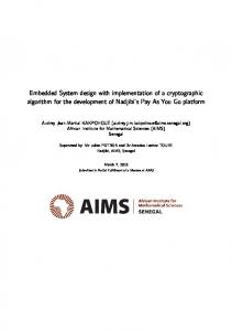
3. RESULTS OBTAINED An analysis of the results of the kinematic model is performed, based on the MOVEJ, MOVES and MOVEC commands. To do this, we start from a known position and generate a path with the different commands implemented. Subsequently a comparison of the data of the movement made by the manipulator and those obtained in the simulation is made. In Figure 4, these joint movements generated by the robot are depicted, where the red stroke represents the expected values and the blue stroke the articular path made by the manipulator.
a) Joint motion of θ1.
b) Joint motion of θ2.
c) Joint motion of θ3.
d) Joint motion of θ4.
Panama City, Panama
6th Engineering, Science and Technology Conference (ESTEC 2017) October 11-13, 2017
6
e) Joint motion of θ5. Figure 4: Joint movement of the 5DOF manipulator. Figure 4 shows the tendency of the blue line to the red line, which corresponds to the actual movement of the joints following the expected movement. The result shows some position variations, which can be improved by changing the PID controller constants [Castillo et al., 2003]. The Cartesian movement of the final effector originated by the coordinated movements of the articulations is represented in the X, Y and Z coordinates shown in Fig. 5. There can be found differences between the paths made by the final effector and the desired one. These differences do not represent a significant position error for the final effector tool used in the test (caliper with 32.5 mm radius).
a) Movement on the X axis.
Panama City, Panama
b) Movement on the Y axis.
6th Engineering, Science and Technology Conference (ESTEC 2017) October 11-13, 2017
7
c) Movement on the Z axis. Figure 5: Cartesian movement of the end effector of the 5DOF manipulator. 4. CONCLUSION Three path algorithms are implemented, MOVEJ, MOVES and MOVEC, which provide a sequence of points in the joint space to generate the different movements (articular, linear and circular). The interpolations of trajectories in the Cartesian space (MOVES and MOVEC), it is necessary to calculate the MCI to find the articular values of each interpolated Cartesian point [Deshpande], which implies that it requires more processing in these commands, compared to MOVEJ. Combining the LabView programming platform and the CompactRio industrial controller, they provide a complete variable monitoring and control system to design, to create prototype and deploy programs with greater efficiency, speed and power in a good controller. The use of rigorous mathematical models allows to obtain the algorithms that generate trajectories, which provide articular and Cartesian coordinates for the movement of the manipulator. In this case (Figure 5), the actual coordinates of the final effector show oscillations on the desired coordinates. These results are acceptable as they are within the tolerance of the tool used for testing (caliper with radius of 32.5 mm).
AUTHORIZATION AND DISCLAIMER Authors authorize ESTEC to publish the papers in the conference proceedings. Neither ESTEC nor the editors are responsible either for the content or for the implications of what is expressed in the paper.
REFERENCES Alcaraz Salvago, A. (2012). “Desarrollo de algoritmos de control y movimiento de robots”, mediante LabVIEW Robotics. Barrera, T., Hast, A., & Bengtsson, E. (2004, November). “Incremental spherical linear interpolation”. In The Annual SIGRAD Conference. Special Theme-Environmental Visualization. (No. 013, pp. 7-10). Linköping University Electronic Press. Barrientos, A., Peñín, L. F., Balaguer, C., & Aracil, R. (1997). “Fundamentos de robótica” (Vol. 256). McGrawHill. Págs. 12, 17. Panama City, Panama
6th Engineering, Science and Technology Conference (ESTEC 2017) October 11-13, 2017
8
Castillo, S. A., & Caberta, R. Ñ. (2003). “Caracterización de un robot manipulador articulado”. Coordinación de Mecatrónica, Tesis de Maestría, CENIDET, México, Junio del. Constaín, A., Torres, K., Arango, J., & Vivas, A. (2009). “Modelado, Identificación Paramétrica y Control del Robot SCORBOT-ER 5 PLUS”. In Presentado en el VIII Congreso de la Asociación Colombiana de Automática, Cartagena, Colombia. Chaudhary, H., & Prasad, R. (2011). “Intelligent inverse kinematic control of scorbot-er v plus robot manipulator”. Deshpande, V. A., & George, P. M. (2012). “Analytical Solution for Inverse Kinematics of SCORBOT-ER-Vplus Robot”. International Journal of Emerging Technology and Advanced Engineering. Eberly, D. (2002). “Quaternion algebra and calculus”. Magic Software Inc. Kazemi, M. S., & Dominguez, M. J. (2016, October). “Simulation and evaluation of neuro-controllers applied in a SCORBOT. In Automatica (ICA-ACCA)”, IEEE International Conference on (pp. 1-9). IEEE. Kumar, R. R., & Chand, P. (2015, February). “Inverse kinematics solution for trajectory tracking using artificial neural networks for SCORBOT ER-4u. In Automation, Robotics and Applications (ICARA)”. 6th International Conference on (pp. 364-369). IEEE. Parra Andrade, G. E. (2015). “Control del robot Pionner 3D utilizando una FPGA Rio(Doctoral dissertation, Universidad de las Fuerzas Armadas ESPE”. Carrera de Ingeniería en Electrónica, Automatización y Control.). Rojas, J. H. C., Serrezuela, R. R., López, J. A. Q., Perdomo, K. L. R. (2016). LQR hybrid approach control of a robotic arm two degrees of freedom. International Journal of Applied Engineering Research. 11(17), pp. 92219228 Serrezuela, R. R., Villar, O. F., Zarta, J. R., & Cuenca, Y. H. (2016). The K-Exponential Matrix to solve systems of differential equations deformed. Global Journal of Pure and Applied Mathematics, 12(3), 1921-1945. Serrezuela, R. R., Chavarro, A. F. C., Cardoso, M. Á. T., Toquica, A. L., & Martinez, L. F. O. (2017). Kinematic Modelling of a robotic arm manipulator using MatLab. ARPN Journal of Engineering and Applied Sciences. 12(7), pp. 2037-2045 Siciliano, B., Sciavicco, L., Villani, L., & Oriolo, G. (2010). “Robotics: modelling, planning and control”. Springer Science & Business Media. Zarta, J. R. & Serrezuela, R. R. (2017). Solution of systems of differential equations deformed with KExponential Matrix, In Taekyun Kim, Advanced Mathematics: Theory and applications (p.p. 189-204), India, Delhi.
Panama City, Panama
6th Engineering, Science and Technology Conference (ESTEC 2017) October 11-13, 2017
9