E MBEDDED S YSTEMS P RODUCT L INES : PROCESS AND MODELS JORGE L. DÍAZ-HERRERA Department of Computer Science, Southern Polytechnic State University 1100 South Marietta Parkway, Marietta, GA 30060-2896 Tel: +1 770-528-4281 FAX: 1 770-528-4281 E-mail:
[email protected]
ABSTRACT Software product lines is one of the most promising approaches in software engineering to achieve the elusive goals of increased productivity and quality. For software intensive systems, a reuse-driven product line approach will potentially reduce time-to-market, and improve product quality while reducing uncertainty on cost and schedule estimates. Additional benefits include longer time IN market, amortization of up-front development cost, and reduced training and maintenance costs. Product lines raise reuse to the level of design frameworks, not simply code or component reuse. They capture commonality and adaptability, through domain and variability analyses, to be able to create new products easily by instantiating prefabricated components, adapting their design parameters, and leveraging from established testing suites. In this paper we examine software technology and infrastructure (process) supporting product lines more directly. 1
INTRODUCTION
The projected CPU shipments in the year 2000 worldwide would be more than 8.2 billion units, and the vast majority of them (98%) will find their way into embedded systems [1 ]. The sheer number of such systems (although, the great majority will be running basically the same application) plus the complexities of embedded software development, points to the need for making the software development process less labor intensive. With this increased capability, the complexity of applications is increasing. Embedded software design is further constrained, as compared to conventional software, by the domain requirements for interaction with the physical world. Unlike other information processing systems, embedded software, in most instances, must “embody” the laws of physics to control its environment in real-time, and it is thus hampered by the complexities of the dynamics of the real world. Automation is one possible way to address these problems, and building software from “reusable components” is another. Automating code generation from specifications is not new, but the approach is regaining interest due to novel parsing and source processing technology that “weaves” concerns into code allowing specialization and redeployment automatically [2 , 3 ]. The need for building software out of prefabricated components is also not new and has been explicitly recognized for quite some time now [4 ]. Model-based
software engineering [5 ] supports both systematic reuse and automated code generation. In spite of the amount of work to date focusing on software technology to achieve high levels of reuse, this has remained an elusive goal. Why has this been such a difficult problem? Quite simply, the great majority of software practitioners today still develop applications according to the standard stovepipe approach, whereby systems are created from first principles repeatedly, from scratch. Such practices have a number of drawbacks and shortcomings [6 , 7 ]. We need to move our focus from engineering single systems to engineering families of systems by identifying “reusable” solutions and by automating as much of the process as possible. The overall goal is to produce quality software products consistently and predictably by moving toward an asset-supported, component-based development approach. The idea is to produce multiple products to exploit “economies of scope” [8 ]. Assets that cross several systems take advantage of economies of scope, a benefit that comes from developing one asset used in multiple contexts. Scope economies arise when the cost to develop multiple products together is less than the sum of the cost of developing the products individually. Benefits. The underlying assumption is that the benefits from the reuse of domain specific software components will offset the potential extra cost for the increased organizational complexity. For example, • By creating assets, that support the future development of multiple systems, an organization reduces cycle time and cost of new applications by eliminating redundancy and by producing applications from common assets, as recently reported: a 65% code reduction was achieved at Ericson by redesigning five similar applications into a product line [9 ]. • Building systems from a common component base reduces risk and improves quality by using trusted components. • An asset-based approach allows the management of legacy systems more efficiently, increasing the likelihood of longer time-IN-market. • An organization based on product lines, evolves a common marketing strategy, and strengthens core competency around strategic business interests and goals. However, before all this can happen, we must have an effective development program supported by “systematic reuse.” This requires careful technical and economic
analyses. Although there are technical difficulties, technology alone is not enough for achieving systematic reuse. Reuse has to be an organization-wide strategy, not a project-centered one. The entire organization may need to be redesigned to fall in harmony with the “domain-model building and application construction processes” that are needed to support reuse [10 ]. In the rest of this paper, we describe the technological aspects and standards needed for modeling and developing product lines. Due to space constraints, we do not discuss specific technology in detail. Rather, we suggest a roadmap for the various phases and kinds of artifacts produced. Section 2 introduces systematic reuse. Section 3 presents an infrastructure in its constituent parts, namely process, technology, and artifacts. Section 4 presents a framework incorporating current technological advancements into this infrastructure. We conclude with a discussion of the effort that lies ahead.
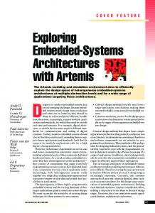
Figure 1 below depicts the relationships between the various aspects of systematic reuse, namely “why,” “what,” and “how.” The organization’s mission and strategic business factors dominate the why-axis. The what-axis depicts the various products, organized as product lines, to address those strategic goals, i.e., the product features that exploit its core competency (leading edge). The how-axis refers to the technical design decisions and crosscutting aspects affecting the various product lines. Why
SYSTEMATIC REUSE
product lines' features Domain
•••
models What
Horizontal reuse
Ve re rtic us al e
Modeling is a key activity in building industrial strength products. Organizations must invest in creating models of the common capabilities of related software applications. Organizations use these models as software assets supporting the creation of products. This process results in the definition of product lines. A product line is a collection of applications sharing a common, managed set of features that satisfy the specific needs of a selected market to fulfill an organization’s mission [11, 12]. Reuse has been considered the cornerstone of software product lines [13 ]. Reuse needs to be planned for since it requires a consolidation of understanding of software systems in a domain in order to exploit commonality and anticipate diversity. For example, taking a product that was built for a specific customer and adapting it for a new customer, would likely result in an inferior product: one that contains undesirable features while lacking other desired features. This is not systematic reuse, but ad-hoc reuse. Earlier definitions of an asset focused more on code. There are several problems with this view. Yes, code from one project can be saved in a “reuse” library in the hope that it will be useful in the future; but unplanned, miscellaneous collections of code components will fail to achieve high-leverage reuse. They would be difficult to locate, understand, and modify, since typically, design information is unavailable and adaptability is not designed-in. Assets serve as templates for the generation of the various work-products during product development. To assure higher probability of success, assets should be organized around ongoing business activities or domains, such as specific mission areas, domain of expertise, or core competencies (e.g., command and control, automotive, web development, etc). Systematic reuse only occurs when reusable assets are planned and created as a separate activity from application development. This formal interaction between asset
Organization (mission) business factors
2
producing and asset utilization activities, whereby applications are assembled from prefabricated artifacts, is known as systematic reuse. • Analysis must explicitly identify variations to anticipate adaptations. • Design for adaptability must be engineered a priori to create assets for future software development1.
ow
•••
n ig s es el D od m
Component base Product Line architectures
Figure 1: Systematic reuse aspects: why, what and how.
2.1
VERTICAL AND HORIZONTAL REUSE
Reuse actually occurs both within a product line and across product lines, a notion discovered earlier and associated with the concepts of horizontal and vertical reuse. Horizontal reuse refers to the use of an asset across several distinct product lines; typically, assets reused in this way tend to be general (i.e., they are application domain-independent), and with a very specific set of functionality. Horizontal reuse solely focuses on specifying components as independent as possible of any domain-specific product decisions. Vertical reuse reefers to the use of assets specially designed for a given product line; these assets are therefore more specific to a set of products (i.e., they are application domain-specific). Vertical reuse focuses on defining product-line specific components whose specification is constrained by the product line architectural decisions. The notions of vertical and horizontal reuse have been formally incorporated in important software construction 1 Assets are indeed investments for future work.
technology such as CORBA [14 ], and this in turns promotes the development of new, higher-level domains as illustrated in Figure 1 (modified from [15 ]). The top layers of the CORBA architecture specify standard objects that can be shared by applications across domains; they are known as the Horizontal CORBA Facilities. Standard objects that are reusable within products in a given product line are referred to as the Vertical (Domain) CORBA Facilities. There are currently eight verticaldomain task forces and special groups, a wealth of information can be found at OMG’s web-site [16 ]. Community & Enterprise Information Portals Health Care
Financial
Insurance
••• other vertical domains
E-Business facilities (Appl. dev., Intelligence, Integration, …)
••• other facilities
Metamodel Interoperability
•••
Distributed Run-time Middleware Figure 2: OMG E-Business Integration Architecture
2.2
ANALYSIS OF VARIATION TO ANTICIPATE ADAPTATION
To address the question of what components are needed requires special, broad analyses of the problem domain to identify the components “present” in the products of a given domain and their specific variants, a process known as domain analysis. Domain analysis results in the definition of product line features documented by domain models. It is at least equally important to identify variations of these features as well as optional features among all product lines members. Domain analysis is a top-down activity considering only applications in a domain of discourse; it may also form the basis for business process reengineering. Design-for-Commonality forms the basis for standardizing assets to build products in a domain by encapsulating common features of related products, and by defining a common architecture for related products. Control-of-Variability is the basis for providing flexibility in the assets to meet requirements for a variety of products without compromising commonality; it requires careful design to include appropriate levels of parameterization, generalization and specialization, and extension. Like commonality, adaptability must be engineered a priori, and thus, analysis must explicitly identify variations that anticipate adaptations. Software architectures and component base designs are becoming the dominant themes. In this way, architectural components encapsulate specific functionality specified by interfaces. Components interact
via architectural connections, which are specified by protocols. Product line architectures capture common high-level structures of related products (design-for-commonality) for building products, identifying common assets, and defining the means for connecting these assets. They allow integration of optional/alternative components (control-of-variability). There is a strong relationship between a component model and architectural constraints [2]. Implementation decisions are outside the scope of the architectural design. They belong in the detailed design of the components and the connectors, which together form the component base. The Component base specifies common functionality across families of systems with direct control of variability. There are different ways to control variability, e.g., class hierarchies, generators, generic parameters (templates), libraries, configurations, etc. Components1, through design-for-commonality, implement those crosscutting aspects that are typically present in the majority of the applications in a domain. Components also capture the way that these aspects may vary from one product to another, and provide plug-in compatibility via standard interfaces – control-of-variability.
3
SYSTEMATIC REUSE PROCESS
The achievement of Design-for-commonality and controlof-variability requires the establishment of a reuse infrastructure. There is a need for an overall framework that integrates the corresponding set of modeling, planning, and asset construction activities necessary for systematic reuse, and that, at the same time, allows the assimilation of technology effectively. There are three basic phases in the overall systematic reuse process: Domain Modeling, Product Line Design and Implementation, and Product Development [17 ]. In Figure 2 below, we illustrate the interrelations between these three phases. We use the formalism introduced by Gunter et al [18 ] in their reference model for requirements engineering to label the arrows. The primary information elements manipulated are in the Domain Knowledge {W}, which encompasses known facts about the domain environment or outside World. The domain modeling activity is constrained by the chosen scope {d} thus sub-setting the domain knowledge to the specific set of products {Wd} based on strategic goals and organizational mission. The Requirements {R} define needs from an end-user point of view. The specification {S} is produced as a precise description of {Wd} from where an optimal Product {P} can be built. The Target Platform, or Machine, {M} provides the
1 We use the term components in its most widely form t o
include requirements, software and hardware architectures as well as blocks (both hardware and software IPs) and their test harnesses.
specific computing environment(s) on which the delivered products and assets will execute. Domain nowledge {W}
cope {d} Domain odels {Wd+R} Domain Modeling
pecification {S}
arget platform {M}
Product Line Design and Implementation
Solution & Configuration models {G}
Product Development
omain libraries{G} equirements {R}
roducts{P}
Figure 3: The relationship between domain modeling, its implementation and product development
Models are subject to validation & verification (not explicitly shown in Figure 3 above) before being baselined. Model validation and verification as well as product validation and verification is carried out through a continuous cycle. One of the most critical questions is to be able to define correct, unambiguous and useful mappings between all these sets of conceptual elements and generated artifacts. For example, it follows that S ⊆ R ⊆ Wd, and that S⇔M*P, where {W+R}= abstract problem model, {S+M}= concrete problem model, G = generic solution model, and P = concrete solution model. A complete analysis of these equations is beyond the scope of our current discussions. Interested readers should look at Gunter [op. cit.]. 3.1
DOMAIN MODELING
The domain modeling process primarily focuses on domain analysis and system-level conceptual design to produce a generic problem description. The various representations of Wd and R contain models from different viewpoints. Each of these models highlights different aspects of the world, needs, and requirements, and are collectively referred to as domain models. Domain models describe typical systems features, including functional and non-functional, as well as mandatory and optional features. Appendix A contains a small example of a product line analysis of the domain of traffic management [19 ], and following the three axes model (see Figure 1). The conceptual system architecture focuses on a common architecture, including both hardware and software, of related systems in such a way that design models become the means for system construction and for incremental growth. New capabilities offered to the user can be introduced through prototyping of new system components (possibly utilizing different implementation technology). Such prototypes coexist alongside the
operational system and may get hardened through incremental reengineering. The architectural model proposes a “best fit” high-level architectural style(s) [20 ] for the kind of problems in hand. The specification contains details of specific behavior and systems properties (e.g., timeliness, and other SWaP1 constraints) complete enough that can be subject to analytical tools. 3.2
DESIGN AND IMPLEMENTATION
The PL design and implementation phase generates generic solutions and configuration models with specific information to support adaptation. Solution models represent both software and hardware architectures (i.e., components and their interfaces) suitable for solving typical problems in the domain. The PL design activity fine-tunes the system-level architectural design with detailed common and flexible product and component structures. These detailed designs correspond to product line architectures and component designs, respectively, documented as solution or design models. Product line architectures depicts the structure for the design of related products and provide models for integrating optional/alternative components. Component Designs specify the structure for the explicit variability of components across products and product lines; they serve as models for specifying and encapsulating commonality. Optional parts are very important. Possible combinations of optional features must be supported by the product line architectural design and the flexibility incorporated in the component design, otherwise it may be impossible to reuse an asset “as-is” because commonality and specificity are mixed. This would make it necessary to modify the asset when reused in the new context, and this should obviously be voided whenever feasible. Configuration models help here. A configuration model maps between the problem models and solution models in terms of product construction rules, which translate capabilities into implementation components. These rules describe legal feature combinations, default settings, etc. For example, certain combinations of features may be not allowed; also, if a product does specify certain features, some reasonable defaults may be assumed and other defaults can be computed based on some other features. The configuration model isolates abstract requirements into specific configurations of components in a product line architecture. The PL implementation includes selection of suitable target platforms, the partitioning and allocation of functionality among hardware/software components, and the implementation of the various components populating the system architecture. The implementation activities define the solution space with all their possible combinations. It also includes a process for the creation of
1 Size, weight, and power.
Architectural models
Component Component models
PRODUCT DEVELOPMENT
A TECHNOLOGY ROADMAP
In this section, we describe in some detail the technological aspects of the systematic reuse processes. Due to space constraints, we do not discuss specific technology in detail. Rather, we suggest a roadmap for its application in the various phases, and outline some problems that have surfaced, especially in relation to object-oriented technology and systematic reuse. We explicitly show the different kinds of models needed during modeling and development, at the same time that we show each of the different levels of abstraction needed for PLs. The former, i.e., kinds of models, represents the different stages of product development ranging from requirements to implementation, whereas the latter indicates the degree of domain information incorporated in the artifact being reused. In general, we need modeling methods and specification languages, architectural styles, frameworks, and architectural description languages, and component metamodels, patterns, and component description languages [21 ]. All these models then serve as the basis for requirements and design analysis for a specific product, and they support creation of component libraries. We illustrate this as shown in Figure 4. In this figure, we juxtaposition software technology representing the various product artifacts– the x-axis, against product generation stages – the y-axis. The x-axis “product’s artifacts” plots software technology used to model the different product artifacts generated during the production process; these models go from high-level artifacts such as requirement models to more specific implementations such as components and systems. Thus, product artifacts fall into three kinds, namely requirement models, architectural models, and component models. At the same time, the y-axis indicates the level of abstraction of these models with respect to domaininformation-dependency. That is, each product artifact model exists at various levels of abstraction ranging from abstract domain-independent models (for Horizontal reuse) and generic solution product line models (for Vertical reuse), to specific product configuration and implementation models (for system delivery). These models are generated during domain engineering, and it is useful to distinguish two levels, namely abstract models and generic solution models.
Solution models Ref. Requirements
Ref. Architectures
Tool Kits
• Domain Model
• Structural Model
• Repository Repository Model Model
Domain Domain information information
The Product development process is multiplexed to correspond to the various product lines. Generative application development can be applied, whereby the application engineer states requirements in abstract terms, from where application generators produce the desired system or component. The actual development process follows any established development framework.
4
independent
3.3
Abstract models Requirements models models
Concrete models SRS/OCD
Designs
Implementation
• Requirements • Features list
• New Components • Product configuration
• New components • New application
specific
reusable software components and their storage and retrieval in the domain library.
Product artifacts abstract
specific
Figure 4: Integrated-MBSE [1 ]: the relationship between the modeling and development activities is driven by technology and models, respectively. The former runs down from domain-independent models (top) to domain specific artifacts (bottom). Product development proceeds from high-level specifications (left), to the concrete realization of application systems (right).
Abstract models provide basic modeling concepts in the domain, and include things like, reference requirements, product lines architectures, and specific problem solutions (e.g., patterns). Analysis models include artifacts such as object and data models (use cases are very useful here), and feature models; whereas design models include architectural representations, patterns, and frameworks. The solution models become reusable assets that serve as templates for the generation of the various workproducts required during actual product development. The concrete models result from the application of the abstract models to a concrete set of requirements by adding specific domain information. See [22] for a survey of DA methods. The design activities are supported by system/software architecture technology, most notably Architecture Description Languages or ADLs [23 ]. Component design is supported by Interface Definition Languages or IDLs. Implementation is supported by component composition technology, most notably Module Interconnection Languages [24 ] such as Ada and Java1. The domain libraries contain generic solutions and components that for a given target platform M satisfies the set of needs described by {W,R,S}. It involves the use of domain-specific languages, code generators and component libraries. Two fundamental component features that affect composition ability and reuse-payoff are scope and granularity. A component’s scope can be domainindependent, domain-specific, or product-specific. The second component feature of granularity has two 1 Non modular languages such as C and C++ make use of
environment provided capabilities such as UNIX header files to support “composability.”
dimensions, namely fine-grained (small-scale) and coarsegrain (large-scale) granularity. The former is typically found in domain-independent components, whereas the latter are typical of application subsystems, or semifinished applications (such as frameworks). Component functionality is less with the size of it, but reuse profit is directly proportional with size. A domain-independent component has a general purpose with broad applicability used in many domains (across boundaries). Components of this type are almost entirely abstract data types such as list managers, mathematical functions, user-interface toolkits and database management systems. The term horizontal reuse is commonly used to refer to domain-independent components. More recently, these issues have reached the programming level with the notion of “adapters” and aspect-oriented programming as in AspecJ (from Xerox [3]), Hyper/J (from IBM [2]), and Demeter [25 ]. Domain-specific components have more limited applicability, and are especially reusable within a specific application domain. The term vertical reuse is commonly used to refer to these components. The semantics of the component are domain-dependent, and hence have little or no use outside domain, and are things like packages that compute taxes, flight control laws, scheduling routines, etc. Such domain-specific components make certain assumptions about how they will be used, reducing generality but increasing its usability1. Product-specific components are reusable within a specific product line. The semantics of the component are bound to a specific application type. The product line may dictate a generic architecture, and component roles will be developed to fit it. Typical product-specific components are entire architectures developed internally or in-house– this means that the organization is developing for reuse and providing services internally; and hence it does not have a company barrier between service providers and customers. There are also externally developed productline components – this means that the organization is developing for reuse and providing services on the external market, and hence it does have a company barrier between service providers and customers, which complicates communication. Each component is a means of achieving one or more reusability features. They must have syntactically and semantically clear specification (separate from implementation) and independence from environment (e.g., parametric coupling). A component specification captures its functional description and operability (parameters, conditions, etc.). A description of the connections among the interface elements and level of parameterization and kind of extension (e.g., parametric polymorphism vs. inheritance) enhance adaptability. Users of higher-level components may instead develop their own
1 The traditional
conflict between design-for-reuse and design-with-reuse [Becker 94]
lower-level components to create the parameters needed to instantiate the higher-level component. Currently, organizations are emphasizing componentbased development (CBD) in the hope that this will bring about the elusive goal of systematic reuse. The idea has had certain amount of success in commercial products, such as OMG’s CORBA, Microsoft’s COM, and Sun’s JavaBeans [26 , 27 ], mainly due to “flexibility through a capability of composition” and not necessarily due to technological developments.
5
CONCLUSIONS
In this paper we have argued establishing a causal relationship between models representing reusable assets, created by applying first principles, and the application of these models to actually develop the delivered application, by the routine application of solution models. We conjecture that the separation of models and product artifacts provides a suitable framework for integrating technology in the pursuit of systematic reuse. It is increasingly clear that developers require software models to be able to build new systems as variations of “old” systems. A prime example of this promising technology can be observed in the development of CORBA and its recent focus on domain technology. With these important efforts we are at the brink of finally beginning to have domain-specific engineering handbooks, a most critical component of an industrial-strength engineering discipline for software. Organizations must invest in creating models of the common capabilities of related software applications, a process commonly known as domain engineering. Organizations use these models as software assets supporting the creation of products that meet increasingly changing requirements, a process also commonly known as application engineering. Domain engineering is a development-for-reuse process to create software assets, whereas Application engineering is a development-withreuse process to create specific systems with these prefabricated assets. An important aspect to secure institutionalization of systematic reuse is the attainment of “economies of scope.” Component-based development focuses on structure of a set of components, embodying features within a domain, leveraging prior investment to maximum degree in support of developing multiple products. Components, objects, and architectures will all be important parts of the next generation of software development technologies. Object-oriented technology does provide superior technical support for code reuse, however it by itself is not enough for institutionalized systematic reuse. Interestingly enough, claims are being made that object technology is neither necessary nor sufficient for systematic component-based development. (It is worth emphasizing that component-based development seems to work with and without objects for additional examples
visit the SEI web page on experiences [28 ]). One problem with object-oriented development is the low level of granularity of the assets being reused. Furthermore, the perceived benefits of reusing patterns and frameworks will not be materialized unless they are taken into account by the application development process. The reason for this is that, in contrast with functionally decomposed systems, object-oriented systems will not have high-level functions that map directly to the functional requirements. This information is not easily extracted from the code either since the focus there is on inheritance. Object-oriented systems quickly become monolithic pieces with difficult to detach “components.” Current object-oriented component technology (including JavaBeans, ActiveX, COM, etc) imposes severe constraints on the components, tightly coupling them to implementation infrastructure. Truly reusable components must be specified as free of constraints as possible. A fundamental change in the traditional objectoriented analysis process to accommodate for systematic reuse is the need for a more formal variability analysis. The development process for domain-specific components (frameworks) should thus follow the traditional domain analysis process. Product line domain analysis must be done (not just domain analysis of one application domain) with emphasis on variability analysis. It is also important to keep domain-independent, domain-specific, and product-specific components apart and possibly physically separate. REFERENCES [1 ]
Tennenhouse, D. “Proactive Computing” Communications of the ACM, Vol. 43, No.5.
[2 ]
P. Tarr, H. Ossher, W. Harrison and S.M. Sutton, Jr. “N Degrees of Separation: Multi-Dimensional Separation of Concerns.” International Conference on Software Engineering, May, 1999.
[3 ]
Kiczales, G., Lamping, J. Mendhekar, A., Maeda, C., Videira Lopes, C., Loingtier, J-M., and J. Irwin. “Aspect-Oriented Programming.” European Conference on Object-Oriented Programming, Finland. Springer-Verlag LNCS 1241. June 1997.
[7 ]
Brownsword, and Paul Clements “A Case Study in Successful Product Line Management.” CMU/SEI96-TR-016. Pittsburgh, Pa.: Software Engineering Institute, Carnegie Mellon University, 1996.
[8 ]
Withey, J. “Investment Analysis of Software Assets for Product Lines.” CMU/SEI-96-TR-010. Pittsburgh, Pa.: Software Engineering Institute, Carnegie Mellon University. 1996.
[9 ]
Bratthall, L. and P. Runeson. “Architecture Design Recovery of a Family of Embedded Software Systems.” In proceedings on TC2 First Working IFIP Conference on Software Architecture. P. Donohoe, Ed. Kluwer Academic Pub. 1999.
[10 ] Jacobson, I. (1996) “Succeeding with Objects: Reuse in Reality.” Object Magazine (July):94-96. [11 ] Cohen, S., Friedman, Martin, Solderitsch, and Webster. “Product Line Identification for ESCHanscom.” CMU/SEI-95-SR-024, Pittsburgh, Pa.: Software Engineering Institute, Carnegie Mellon University. 1995. [12 ] Weiss, D. M. and C. T. R. Lai. Software ProductLine Engineering. Addison-Wesley, Reading MA. 1999. [13 ] Díaz-Herrera, Peter Knauber and Giancarlo Succi. “Issues and Models in Software Product Lines” International Journal of Software Engineering and Knowledge Engineering, Vol. 10, no. 4. [14 ] Siegel “OMG Overview: CORBA and the OMA in Enterprise Computing.” (Communications of the ACM, vol. 41, no. 10, 1998) pp 37-43. [15] Iyegar, S. (Unisys Corp.) “CWM Audio Briefing: the Key to Integrating Business Intelligence.” http://www.omg.org/news/releases/pr2000/cwm/whi tepaper.htm [16 ] OMG “CORBABusiness Objects.” http://www.omg.org/homepages/bodtf/
[4]
McIlroy, D. “Mass produced software components.” NATO Conf. On Software Engineering. (1968) pp138-155.
[17 ] Diaz-Herrera, J. L. and V. Madissetti. “Embedded Systems Product Lines.” Software product lines, ICSE Workshop. Limerick, Ireland. June, 2000.
[5 ]
Díaz-Herrera, J.L. and R. Schroeder. “Product Line Software Development for Embedded Systems: a Model-Based, Component-Driven approach” OOPSLA’99 workshop on Object Technology and Product Lines, Denver Oct. 1999
[18 ] Gunter, C. A., Gunter, E. L., Jackson, M. and P. Zave. A Reference Model for Requirements and Specifications. (IEEE Software, May/June 2000) pp 37-43.
[6 ]
Brown, A. W. and K. C. Wallnau. “The Current State of CBSE.” IEEE Software (1998).
[19 ] Mochizuki, M., Suzuki, A. and T. Tajima “UTMS System Architecture.” Sixth Annual World Congress on ITS, Toronto, November 8-12,1999.
[20 ] Sahw, M. and D. Garlan Software Architectures: Perspectives on an Emerging Discipline. PrenticeHall, Upper Saddle River, NJ, 1996. [21 ] Díaz-Herrera, J.L. “Studying the Tradeoff between Generality and Specificity in Developing Product Lines” Proceedings On Software Engineering and Knowledge Engineering, Kaiserslautern, Germany, June 16-19, 1999. [22 ] Arango, G. “Domain Analysis Methods.” In Software Reusability. Chichester, England: Ellis Horwood, 1994) pp 17-49. [23 ] Hayes-Roth, F. Architecture-Based Acquisition and Development of Software. ARPA Domain-Specific Software Architecture Program. Palo Alto, CA: Teknowledge Federal Systems, 1994. [24 ] Prieto-Diaz, R. and J. Neighbors. “Module Interconnection Languages.” (Journal of Systems and Software, vol. 6, Nov, 1986) pp. 307-334. [25 ] Lieberherr, K. Adaptive Object-Oriented Software: The Demeter Method with Propagation Patterns. (Publisher: PWS Publishing Company, 1996.) [26 ] Leavens, G. T. and M. Sitaraman. Foundations of Component-Based Systems. Cambridge University Press. Cambridge, UK. 2000. [27 ] Szyperski C. Component Software: Beyond ObjectOriented Programming. Addison-Wesley, Harlow, UK. 1998. [28 ] http://www.sei.cmu.edu/plp/plp_case_studies.html
JORGE L. DÍAZ-HERRERA is Professor of Computer Science at Southern Polytechnic State University, where he was Department Head for two years. He is also a part-time visiting scientist at the Software Engineering Institute, Carnegie Mellon University, where he spent four and half years as a senior member of the technical staff teaching in Carnegie Mellon's Master of Software Engineering, and conducting research in the Product Line Engineering program. He was in the faculty of the departments of Computer Science at George Mason University, in Fairfax Virginia, and at SUNYBinghamton, N.Y. He chaired several national and international conferences. He was an ACM National Lecturer for four consecutive years. He has more than 60 publications. Dr. Díaz-Herrera completed a Systems Analysis degree in 1974 in Venezuela, and both a Master and a Ph.D. degree in computer studies from the University of Lancaster in England in 1977 and 1981
respectively. He has been a member of the British Computer Society since 1977, ACM since 1978, IEEE since 1983, and of the American Society for Engineering Education since 1989.
APPENDIX A: PL ANALYSIS EXAMPLE The following example of product lines is based on the Universal Traffic Management Society of Japan established in 1993 for the achievement of a safe, comfortable and environment friendly automotive society. The following subsections refer to Figure 3 above. Domain analysis will identify the various systems features, commonalities and differences. The domain design will identify a high-level architecture with an explicit identification of the points of variation (hot-spots) and corresponding component flexibility.
WHY: MISSION AND STRATEGIC GOALS The traffic management needs can be grouped as follows, each serving a different constituency, such as law enforcement and education, managing traffic accidents or emergency cases, managing traffic in large scale disasters, managing drivers and driving licenses, managing road usage (e.g., freight), managing non-traffic police activities. Traffic management dimension defines various business objectives or strategic goals. These include secure satisfactory traveling circumstances, optimum resource distribution, and public welfare. These translate into optimum allocation of traffic related resources (e.g. traffic demand management), arrangement of rights of way in time division (e.g. traffic signaling), arrangement of rights of way in space division (e.g. route guidance or regulation), protection of people (e.g. pedestrians, physically impaired and the aged), etc. WHAT: PRODUCT LINES: The achievement of the strategic goals can be met by the definition of the following products grouped into three product lines: PRODUCT LINE 1: SAFETY • DSSS: Driving Safety Support Systems • HELP: Help system for Emergency Life saving and Public safety • FAST: Fast Emergency Vehicle Preemption systems PRODUCT LINE 2: CONTROL • DRGS: Dynamic Route Guidance Systems • MOCS: Mobile Operation Control Systems • ITCS: Integrated Traffic Control Systems • PTPS: Public Transportation Priority Systems PRODUCT LINE 3: INFORMATION MANAGEMENT • EPMS: Environment Protection Management Systems • IIIS: Intelligent Integrated ITV Systems • AMIS: Advanced Mobile Information Systems • PICS: Pedestrian Information and Communication systems
HOW: ASSET BASE: These products share the following common elements: ACTORS walking people driving people outside people (operators & administrators) roads vehicle detectors
TRAFFIC INFORMATION FEATURES Information acquisition whether and environment travel time traffic information (video & still image police communication strategy: traffic planning tactics: control parameters Information dissemination traffic information to drivers, pre-trip drivers, all travelers public transport information to travelers Warning information hazard information at dangerous places warning information at roads driving information about neighboring Vehicles driving information on high-speed traffic
TRAFFIC MANAGEMENT FEATURES Controlling elements route guidance arterial/wide area traffic control intersection traffic control lane oriented traffic control zone oriented traffic control Controlled elements pedestrians (including wheel chairs) the environment public transportation (include. taxis) commercial vehicles emergency vehicles grade crossing special vehicles (governor's, pope's)