Embedding a Wireless Transmitter within the Space and Power Constraints of an Electronic Untethered Microrobot Sylvain Martel, Senior Member, IEEE, and Walder André, Student Member, IEEE
Abstract—Standard transmission methods such as RF have been considered for untethered robots that need to send messages and information to an external computer. But, as the overall sizes of such robots decrease, the implementation of such transmission systems within the space and power constraints becomes more challenging. For microrobots, the challenge is even greater and furthermore, the overall size of such microrobots can often decrease to a level where the implementation of transmitters as we know them today, cannot be implemented due to several reasons. First, known transmitters require a relatively large amount of electrical power, which is a concern for microrobots. Indeed, a power source such as a battery cannot be embedded since it will be much larger than the microrobot itself. Power can be induced but again, the size of the reception coils capable of providing sufficient electrical power for the transmitter would also be much larger than the robot itself. Another constraint is the overall size of the transmission antennae which would be larger than a single microrobot. As such, a new transmission scheme that can be embedded in an intelligent microrobot with overall dimensions slightly larger than the human hair thickness is briefly introduced. When operating in proximity of an extremely sensitive magnetic receptor, a small electrical current provided by miniature photovoltaic cells on top of the microrobot can be used to generate a local electromagnetic field perturbation sufficiently high to be detected. By modulating such local electromagnetic field from sensory information captured by the microrobot, data and communication commands can be transmitted based on sensory information to an external central computer that could be used to coordinate a swarm of such intelligent microrobots.
M
I. INTRODUCTION
icrorobots with overall dimensions in the micrometerscales have been studied for several applications and in particular for the implementation of microfactories and for medical interventions inside the human body [1]. For microfactories, decreasing the overall size of each robot means that a higher density of instrumented robots per
Manuscript received April 14, 2009. This work was supported in part by the Canada Research Chair (CRC) in Micro/Nanosystem Development, Fabrication and Validation and grants from the National Sciences and Engineering Research Council of Canada (NSERC), the Province of Québec, and the Canada Foundation for Innovation (CFI). S. Martel (corresponding author) is with the NanoRobotics Laboratory, Department of Computer and Software Engineering, and the Institute of Biomedical Engineering, École Polytechnique de Montréal (EPM), Montréal (Québec), P.O. Box 6079 Station Centre-ville, H3C 3A7 Canada (phone: 514-340-4711 ext. 5098; fax: 514-340-4658; e-mail:
[email protected]). W. André is with the NanoRobotics Laboratory at EPM (
[email protected]).
surface area can be achieved. This in turn will translate into a higher number of operations being executed per second on a given surface area. A higher density of microrobots achieved through a higher level of miniaturization also means that the travel distance between successive working sites is reduced, which often leads to less travel time and hence, more time dedicated for work. In other applications, miniaturization is essential to allow such robots to operate in a given environment. Microrobots designed to operate in the human’s vasculature is one important example where substantial efforts have been dedicated in recent years. Since the diameters of the human’s blood vessels range from a few millimeters in vessels such as arteries down to a few micrometers in the smallest capillaries, reducing the overall dimensions of such medical microrobots would allow them to operate in a higher percentage of the vascular network being made of nearly 100,000 km of blood vessels in an adult. Although recent advances in microelectronics allow us to implement some level of intelligence in micrometer-scale untethered robots, other aspects such as actuation, power and communication remain challenging at such a scale. In particular, powering such microrobot remains a huge problem in achieving further miniaturization. As such, it is essential to implement functions that would minimize the amount of electrical power required by each microrobot. For instance, actuation including displacement of such untethered microrobots should rely on an external source of power and as such, magnetically-driven microrobots relying on external coils to generate vectored displacement forces have been implemented [2-3] or using flagellated magnetotactic bacteria [4-5]. But for some functions being embedded in the microrobot, electrical power is required. This is the case for the wireless data transmitter embedded in an intelligent untethered microrobot. Therefore, not only the new transmitter must be able to consume a minimum amount of electrical power, it must also be capable to operate within the constraints imposed by the overall dimensions of each microrobot. As such, the technical limits in wireless power transmission for such microrobot must first be estimated. II. WIRELESS POWER TRANSMISSION FOR UNTETHERED MICROROBOTS When it comes to wireless power transmission, inductive coupling is often used. With this near field approach, the
secondary coil used to receive power, must be implemented on the microrobot. The size of the secondary coil with the required electronics imposes serious constraints on the level of miniaturization that can be achieved. Far field approaches such as radio and microwave-based power transmissions have the same drawbacks. On the other hand, photonicbased power transmissions allow the use of a miniature receiver in the form of photovoltaic cells that can be tuned to the wavelength of a monochromatic light source. As such, the use of a monochromatic 830nm light source becomes a serious candidate for untethered intelligent microrobots operating in the human body. Indeed, recent studies confirmed that the 830nm wavelength achieves the greatest penetration depth in human by being less absorbed by the tissue. This suggests that depending on the power of the laser source and considering the egg-shape dispersion inside the tissue at such wavelength, that a microrobot navigating and/or operating in the vascular network while being equipped with photovoltaic cells could receive a small but potentially sufficient amount of photons to power the onboard electronics when located relatively far below the surface of the skin. Recent experimental data [6] confirm that a few microamperes of electrical current can be converted from photovoltaic cells implemented on a symmetrical surface of no more than approximately 200µm across on the surface of a CMOS-based microrobot where power/area of ~110pW/µm2 has been recorded. Other experimental results using a CMOS 0.18µm process and using both lateral and vertical PN-junctions provided a short circuit of 70µA and an open voltage of 0.48V from a 400µm × 400 µm photocell. In this particular implementation, the lateral PN-junctions were formed with the juxtaposition of alternate concentric squares of P and N-types in order to create more PN-junctions over the surface of the photocell, hence increasing the output photonic current. The vertical PN-junctions were formed by the P+ and the N-well, and the N+ with the P-substrate [6]. Nonetheless, it becomes evident that the power consumption of the electronics including the transmitter would need to be as low as possible and as such, it becomes difficult to consider traditional RF or the like transmitter designs aiming at passing commands and/or data from the microrobot to an external computer. III. WIRELESS TRANSMITTER FOR UNTETHERED MICROROBOTS Miniature FM transmitters can be easily constructed, requiring only a few components. But in such transmitters, some components may be too large to be embedded in a microrobot. For instance, the design of these transmitters often requires an inductance which can be built using several turns of hookup wires, and/or requiring capacitors or other discrete components that may be orders of magnitudes larger than the microrobot itself. The antennae and particularly its length is also an obstacle to the
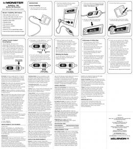
implementation of such transmitter besides the transmission power required to be detected by a receiver. Another typical example showing the limitation of today’s technology is the SZA-12 ultra-miniature UHF transmitter using ZA675 Zinc Air batteries for power. The overall size including the battery is 12mm × 12mm × 11mm which is far more than the overall dimensions of a single microrobot. Many examples of electronic transmitters can be found but the conclusion is that the overall dimensions and the power required prevented them to be embedded in microrobots. It then becomes obvious that the strategy to be used for reducing both the overall size of the transmitter and the transmission power required for communication is to increase the sensitivity of the receiver and to implement a different source of transmission. IV. WIRELESS TRANSMISSION USING LOCAL ELECTROMAGNETIC FIELD GENERATION Our principle of wireless transmission using local electromagnetic field generation for sensor-based intelligent microrobots being powered by photonic energy is depicted in Fig. 1. ENERGY SOURCE
MAGNETIC SENSOR
TRANSMISSIONS
PHOTONS
PHOTOVOLTAIC CELLS
TRANSMISSION PAD
ELECTRONICS (INTELLIGENCE)
SENSOR MICROROBOT SENSORY SIGNALS
Fig. 1 - Simplified schematic diagram showing the principle of the transmitter for a microrobot.
As depicted in Fig. 1, a flow of protons from a remote photonic energy source is captured by photovoltaic cells and converted as electrons providing the electrical current necessary for the operation of the embedded electronics. To minimize the electrical power requirement, a minimum functional electronic circuit is implemented. The latter provides the minimum intelligence for the microrobot. Again to minimize electrical power requirement, the same electronic circuit switches the photovoltaic current between the sensor and the transmission pad in a time multiplexedfashion. The signal captured by the sensor (typically implemented with an ISFET) modulates the signal at the transmission pad. In other words, stronger is the sensory signal and higher is the transmission frequency. Such sensory signal can take various forms including but not limited to pH or oxygen level.
The modulated transmission electrical current is routed by the embedded electronic circuit to the transmission pad. The transmission pad is defined here and a region where the conductor carrying the modulated transmission current is exposed, i.e. not magnetically shielded as it is the case for the other electrical conductors embedded in the intelligent microrobot. This modulated transmission electric current generates a local electromagnetic field at the transmission pad according to the Biot-Savart Law. We recall that the Biot-Savart Law is well known as being an equation in electromagnetism that describes the magnetic field B generated by an electric current. It is defined as →
Figure 1A shows experimental results obtained with a magnetic sensor neared an untethered microrobot with overall dimensions of only 300 × 300µm.
A
B VERSION 1
VERSION 2
→
µ I dL × rˆ dB = 0 . 4π R 2
(1)
In Eq. 1, dB is the differential contribution to the magnetic field resulting from the differential element of the wire or conductor, I is the electric current, R is the distance from the wire element to the point at which the field is being computed, dL is a vector whose magnitude is the length of the differential element of the conductor with direction being the same as the direction of conventional electrical current and which is multiplied by the displacement vector in the direction pointing from the wire element towards the point at which the field is being computed, and µ0 = 4π × 107 T · m A-1. Eq. 1 can be re-written as µ I sin θ dB = 0 . (2) 4π R 2 For a transmission pad implemented as a loop, Eq. 2 is simplified since θ = 90o for all points along the path and the distance to the field point is constant. As such, the integral becomes µI µI µI B = 0 2 v∫ dL = 0 2 2π R = 0 (3) 4π R 4π R 2R Similarly, to determine transmission distance z perpendicular to the transmission pad made of a current loop, involves integrating the z-component. Hence we will have µ IdL R dBz = 0 . (4) 4π z 2 + R 2 3/ 2
(
)
Because of the symmetry, all terms in Eq. 4 are constant except for the distance element dL which when integrated gives the circumference of the loop (circle). The magnetic field at a distance z can then be computed as µ 2π R 2 I Bz = 0 . (5) 4π z 2 + R 2 3/ 2
(
V. IMPLEMENTATION AND EXPERIMENTAL RESULTS
)
As depicted in Eq. 5, it is expected that although wireless transmission from an intelligent microrobot is possible, the sensibility of the receiver at a distance z must be sufficient to compensate from an attenuated signal of the electromagnetic field.
C
D
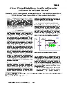
Fig. 2 – A. Signal recorded from a magnetic sensor in proximity of the microrobot. B. Version 2 of the microrobot used for the tests besides the preceding version of the microrobot. C, D - Displacement of the microrobot in an aqueous medium.
As depicted in Fig. 2A, A 1 kHz signal (bottom) is being recorded wirelessly (top signal) from a microrobot (Fig. 2B – version 2) with an overall size of no more than 300 × 300µm. Although weak, the experiment shows that wireless transmission at such a scale is possible using a photon-based energy source to power the microrobot. The magnetoresistance sensor had the following characteristics: magnetic field intensity of 0.8%/G, field noise (10 – 100 kHz): 1090nT/Hz. VI. DISCUSSION AND CONCLUSION The previous experimental results gathered with the second version of the microrobot (overall dimensions of 300 × 300µm) with a transmission-pad implemented as a current loop, confirm that the local electromagnetic field created by the 10µA current can be used to establish communication with an external computer. On the other hand, as the overall size of the microrobot decreases, the amount of photonic current will decrease proportionally, which will lead to a proportional decrease of Bz. Hence, the sensitivity of the sensor used to receive transmitted data from the microrobot must increase for a given distance from the transmission pad. Furthermore, the spatial resolution of the magnetic sensor must be sufficient to detect the local magnetic field in the vicinity of the microrobot. As such, a swarm of microrobots [7] transmitting the same message could be used to compensate for the lack of spatial resolution of the magnetic sensor. An Ion Sensitive Emission Transistor (ISFET) has been considered for the microrobot the sense the environment. A gradient such as the pH being sensed by ISFET embedded in
the microrobot could then be used to influence the displacement of the microrobot itself. Transmitted data could be interpreted by an external computer as commands to assist each robot in their displacement for finding a chemical source for instance, similar to chemotaxis where the swimming paths of flagellated bacteria are influenced by nutrient gradients. REFERENCES [1] Martel S., “Nanorobots for microfactories to operations in the human body and robots propelled by bacteria”, DECOM 07, Ýzmir, Turkey, May 17-18, 2007. [2] Chanu A. and Martel S., “MRI driven nano biosensor for wireless physiological data measurements using deformable polymers coated magnetoelastic devices”, The 7th IEEE International Conference on Nanotechnology (IEEE-NANO), Hong Kong, China, Aug. 2-5, 2007. [3] Martel S., “Magnetic resonance propulsion, control and tracking at 24 Hz of an untethered device in the carotid artery of a living animal: an important step in the development of medical micro- and nanorobots”, 29th Annual International Conference of the IEEE Engineering in Medicine and Biology Society (EMBS), Lyon, France, Aug. 23-26, 2007. [4] Martel S. and Mohammadi M. “Controllable bacterial actuators for nanorobots” ACTUATOR 2008, 11th International Conference on New Actuators and 5th International Exhibition on Smart Actuators and Drive Systems, Bremen, Germany, June 9-11, 2008. [5] Martel S., Mohammadi M., Felfoul O., Lu Z., and Pouponneau P., “Flagellated magnetotactic bacteria as controlled MRI-trackable propulsion and steering systems for medical nanorobots operating in the human microvasculature,” International Journal of Robotics Research (IJRR), vol. 28, no. 4, pp. 571-582, April 2009. [6] André W. and Martel S., “Micro-photovoltaic cells designed for magnetotaxis-based controlled bacterial microrobots,” Transactions of the Institute of Electronics, Information and Communication Engineers (IEICE), IEICE Electronics Express, Vol. 5, No. 3 pp.101-106, 2008. [7] Martel S., André W., Mohammadi M. and Lu Z. “Towards swarms of communication-enable and intelligent sensotaxis-based bacterial microrobots capable of collective tasks in an aqueous medium,” The 2009 IEEE International Conference on Robotics and Automation (ICRA), Kobe, Japan, 2009.