Abstractâ This paper describes the architecture and specifications of advanced real-time simulators capable of accurately simulating electrical power grids and ...
Paper Accepted for the International Conference on Power Systems (ICPS’07), Bangalore, India. December 12-14, 2007
1
eMEGAsim: An Open High-Performance Distributed Real-Time Power Grid Simulator. Architecture and Specification Jean Bélanger, Vincent Lapointe, Christian Dufour and Loic Schoen – Opal-RT Technologies Inc.
Cost Abstract— This paper describes the architecture and specifications of advanced real-time simulators capable of accurately simulating electrical power grids and power electronic systems of any size. The OPAL-RT eMEGAsim simulator is based on modern high-performance distributed supercomputer technology comprised of off-the-shelf INTEL or AMD multi-core processors. Several eight-processor shared-memory supercomputer modules are interconnected with fast PCI Express communication links and IO systems controlled by Field Programmable Gate Array (FPGA) Xilinx processors capable of executing sub-system models with time step below 250 nanoseconds. A brief history of the evolution of real-time simulators will be given followed by the main specification requirements for each type of application, a description of the simulator architecture and a typical application case. Index Terms-- real-time simulation, accelerated simulation, off-line simulation, electrical network, power grid, FACTS, wind energy, distributed generation, ship energy generation, propulsion system, railway power feeding system, doubly-fed induction generator, electromagnetic transients, hardware-inthe-loop, FPGA, multi-core processor, PCI Express
I. INTRODUCTION AND HISTORY
T
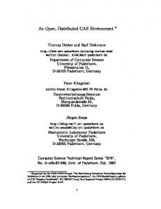
HE design of large high-voltage transmission systems has always required the use of powerful real-time simulators capable of simulating electromagnetic transients expected during normal and abnormal operating conditions. Real-time simulators were also the only available tools for testing, under realistic conditions, new interconnection and control technologies, now called FACTS, aimed at improving overall power system performance. A. The Evolution of Large-Scale Real-time Simulators As described in Figure 1, real-time simulators have evolved over the past 50 years from fully analog simulators, called Transient Network Analysers (TNA), to hybrid digital-analog simulators, to today’s fully digital simulators. Historically, the development of real-time simulators of all kinds has been conducted and financed by large utilities, such as HydroQuébec and Electricity de France, as well as manufacturers and research institutions. Although many utilities have commercialized simulation technologies and installed largescale simulators in locations worldwide, this activity has largely ceased in the past two to three years.
Analog Simulators Hybrid (Analog/Digital) Simulators Digital Supercomputer Simulators Digital Custom Simulators
High-accuracy real-time simulators can now be implemented using off-the-shelf technologies
1960
1970
1980
OPAL-RT eMEGAsim eDRIVEsim
Digital COTS Simulators FPGA SimOC
1990
2000
Figure 1. Evolution of real-time simulation technologies vs cost
B. Large-Scale Real-time Simulators are still required It could be argued that further development of large-scale real-time simulators is no longer necessary since most utilities involved in the deployment of high-voltage systems are fully equipped with simulation facilities. Furthermore, the ever increasing power of standard processors and the availability of powerful off-line electromagnetic simulation programs such as EMTP-RV [1] provide an adequate methodology for evaluating electromagnetic transients, diminishing the need for real-time simulators which, until recently, were used to perform such analysis primarily because they provided superior performance in comparison to computer-based simulation tools. However, private companies, including OPAL-RT Technologies from Quebec, persist in the development and commercialization of fully digital real-time simulators. They are used by utilities, manufacturers, universities and research institutions requiring the capability to simulate complex power grid and power electronic systems in real-time for Hardwarein-the-loop (HIL) applications. In fact, the need for real-time simulators is increasing, not only for high-voltage transmission and interconnection projects but also for the analysis of new technologies related to the integration of distributed generation (DG) and sophisticated distribution and loads installed on in-land power grids, large ships, aircraft, and spacecraft.
Paper Accepted for the International Conference on Power Systems (ICPS’07), Bangalore, India. December 12-14, 2007 II.
MAIN SIMULATOR REQUIREMENTS
A. New Challenges for Power System Engineers and Simulator Manufacturers The integration of wind farms with power grids is an excellent example of the many challenges facing electrical engineers in the power industry today. The development of photovoltaic cells and other power-electronic-based distributed energy generation systems integrated with domestic loads and future plug-in electrical cars is also a new challenge. IGBT-based FACTS such as active filters and other fast converters will also create different types of transients if compared to thyristor-based FACTS. All the above applications take full advantage of several very fast and distributed power electronic systems which, in many cases, are of innovative design and consequently have never been integrated together or with a power grid. Furthermore, in most cases, these distributed systems are designed, manufactured and commercialized as individual off-the-shelf products, with no consideration given to total system performance. Validated models suitable for electromagnetic transients, as well as dynamic stability analysis under normal and abnormal unbalanced conditions, are usually not available. This poses a new and significant challenge to utility and system engineers who must guarantee total system performance and availability. B. Time step and computational power for conventional applications Another challenge facing power system specialists is selecting a real-time simulator that will meet their needs not only for conventional power grid applications, but also for distributed Pentium, OPTERON, MULTI-CORE … Slow dynamic
Number of CPU
100 20 10 4 2
Very large Dyn. Sim.
generation systems. The key parameters that will dictate the capability, size, and consequently the cost of the simulator are 1) the frequency of the highest transients to simulate, which dictate the minimum time step, and 2) the complexity or the size of the system to simulate, which dictates the number of processors. The number of IO channels required to interface the simulator to a real controller for HIL applications is also a critically important parameter affecting the total performance and cost of the simulator. Figure 2, below, outlines the typical time step and number of high-end processors required for each type of application. On the left side of this chart, mechanical systems with slow dynamic will generally require a simulation time step between 1 and 10 milliseconds according to the rule of thumb that the simulation step should be smaller than 5% to 10 % of the smallest time constant of the system. A smaller time step may be required to maintain numerical stability of stiff systems. Simulation time steps as low as 100 microseconds to 500 microseconds may be required to simulate friction phenomenon. A simulator with one or two high-end processors would normally be sufficient for such complex systems. However, large integration HIL tests and the simulation of several subsystems may require a significantly higher number of processors. This class of system is typically simulated with state-space technique, standard in Simulink, or with specialized solvers. eMEGAsim’s full integration with MATLAB, SIMULINK and RTW is a real advantage for these types of applications in comparison to simulators based strictly on the nodal technique optimized for power grid simulation but not applicable for complex mechatronics systems.
+ FPGA IO
Slow and fast dynamic and transients Multi-area power systems
Very fast transients
Medium size Multi MULTIPLE FACTS power systems UAVs ACTIVE FILTERS and MULTI-CONVERTER vehicles HIGH-POWER DRIVE Mechanical Small equivalent (1 – 10 MW) systems power systems Robotics for control testing WIND TURBINE Car and High-power drive (1 – 2 MW)) Aircraft 1- 3 kHz PWM dynamic TRAIN, OFF-HIGHWAY ELECTRICAL VEHICLE
1 1 kHz 1000 us
10 kHz 100 us
+ SimOnFPGA Ultra fast transients
SIMULATION TIME STEP BELOW 500 NANOSECOND WOULD BE REQUIRED TO SIMULATE PWM DRIVE WITH 10 kHz CARRIER FREQUENCY WITH CONVENTIONAL FIXED STEP ALGORITHMS WITOUT
Large power system
20 KHz 50 us
40 kHz 25 us
2
INTERCONNECTED LOW-POWER DRIVE SYSTEMS (100 kW) 10-kHz PWM Low-power drive (100 kW) 10-kHz PWM Hybrid vehicles
100 kHz 10 us
Fig 2: Model Sampling Rate and Step Requirement (when OPAL-RT interpolation algorithm is used)
250 kHz 5 us
Very-low-power drive ( 10 kHz PWM IGBT protection Precise models
1 MHz 1us
Paper Accepted for the International Conference on Power Systems (ICPS’07), Bangalore, India. December 12-14, 2007 C. Time step and computational power for conventional power grids The simulation of electromagnetic transients expected in traditional power grids equipped with thyristor-based HVDC and FACTS systems normally requires a time step in the order of 25 microseconds to 50 microseconds. Such time step values are also used for typical off-line simulation with EMTP-RV to represent transients up to about 2 kHz and to simulate detailed controllers with a good representation of fast protection systems. The analysis of non-characteristic harmonics caused by unbalanced thyristor valve firing normally requires the use of a time step below 2 microseconds or interpolation algorithms, which have been a standard feature in eMEGAsim simulators for many years. The number of processors required depends on the size of the power system simulated, in terms of the number of lines, transformers, buses, generators, and complex FACTS systems. The computational power of each processor as well as interprocessor communication overhead also plays a very important role in evaluating the number of processors required. In fact, the only way to effectively evaluate the number of processors required is to develop a benchmark using typical power grid models. The last section of this paper provides an example which supports the conclusion that an eMEGAsim simulator, equipped with 8 high-end processors interfaced by shared-memory, would have the capability to simulate complex power systems as required by most manufacturers, research centers and universities. Several examples are presented in [2]. eMEGAsim simulators take advantage of the computational power available in the latest generation of multi-core high-end processors developed by INTEL and AMD.
Figure. 3. Real-time performance (time-step in µs) according to the number of processor cores used for the distribution of the model (the detailed wind farm connected to a single feeder). Example with a single target computer equipped with dual Intel® Core™2 Quad processors. [14].
Figure 3 illustrates how parallel computational efficiency increases by more than 100% as the number of CPUs used increases. Real-time performance increases by a factor of 5 (from 144 to 28 us) when the number of CPUs used is increased by a factor 3 (from 2 to 6). Such a performance gain is due to eMEGAsim’s efficient use of the large cache memory on multi-core processors and fast on-chip inter-processor shared-memory communication.
3
Custom computer boards using processor chips with external shared-memory and parallel communication interfaces cannot achieve such performance levels at an affordable price. Hence, using off-the-shelf computer components to implement fast parallel real-time simulators is now clearly the best choice. D. Time step and computational power for IGBT-based applications Real-time simulators will play an important role in the design, test and evaluation of new technologies that take advantage of new power electronic devices installed on in-land and embarked distributed generation and distribution power grids. These systems use very fast IGBT-type power electronic switches which provide power electronic engineers with the flexibility they need to invent new system topologies. However, such systems generate system transients with higher frequencies than transients expected in conventional highvoltage power grids and can generate non-characteristic lowfrequency harmonics due to asymmetrical firing (dead-time) and unbalanced conditions. Simulation experts are well aware of the challenges related to the simulation of complex circuits with lumped R-L-C circuits, small transmission lines, and a large number of highspeed switches that are constantly modifying system stateequations. Furthermore, simulating low-power power electronic systems with PWM carrier frequencies between 5 kHz and 20 kHz poses additional challenges since a very small time step value below one microsecond is required [3] to reach an acceptable accuracy level during real-time and fixed-step simulation. Such a requirement can only be met by simulating fast model sub-systems directly on an FPGA processor, a standard feature of eMEGAsim [4] using XILINX VHDL SIMULINK code generators available to all advanced users. Another easier solution is to use the already developed IGBT power converter models provided with eMEGAsim, which includes a real-time interpolation algorithm. These “drag-anddrop” models use a time-stamped technique that samples the IGBT firing gate transitions occurring within the main model step with a resolution of 10 nanoseconds. This timing information is then used at the next time step to correct IGBT and motor currents by interpolating model state variables. As illustrated in Figure 2 and verified through off-line simulation and laboratory results made available by MITSUBISHI [3], time step values of about 10% to 20% of the base carrier frequency period, (i.e. 10 to 20 microseconds for a PWM carrier frequency of 10 kHz), will lead to simulation results “accurate enough” to permit testing of controllers and total system performance during normal and unbalanced fault conditions. This interpolation technology enables the use of standard offthe shelf computer boards, easily programmed by SIMULINK and RTW, in the real-time simulator. Such simulators have been in use for over fours years by leading power electronic equipment manufacturers including TOYOTA (Hybrid
Paper Accepted for the International Conference on Power Systems (ICPS’07), Bangalore, India. December 12-14, 2007 vehicle), MITSUBISHI, HITACHI, and General Electric. E. Application requiring time step below one microsecond This section discusses the applications listed on the right-side of Figure 2 requiring model step values below 1 microsecond. Many Opal-RT customers, particularly manufacturers and IGBT controller developers, have interest in implementing fast controllers directly onto FPGA chips for a number of reasons. FPGA chips may be used in final production-grade controllers or for prototyping ASIC chips. These customers also wish to test controller designs in closed-loop mode by connecting a prototype controller, implemented on an FPGA, DSP or electronic chip, to a real-time simulator exhibiting very low input-output latency. The total latency, measured as the time elapsed between IGBT firing gate transition and the motor or IGBT current response, must be in the order of 1 microsecond or less. Such low latency is required in order to enable testing of fast over-current and over-temperature protection implemented on the controller. Other protection systems may also require fast reaction time. Userprogrammable eMEGAsim FPGA boards provide a total input-output latency of 1.4 microseconds. This latency is primarily limited by the analog output converter update and settling time and can be reduced below 500 nanoseconds, if required. Modeling of high-speed motors with non-sinusoidal backEMF and non-linear inductors also requires a simulation time step below 10 microseconds. However, time step values below 5 to 10 microseconds are difficult to achieve with offthe-shelf computer boards, due to IO communication latency issues. To address this issue, a library of FPGA-based models with a time step of approximately 250 nanoseconds is included with eMEGAsim. Finite-Element based models are also available. In addition, eMEGAsim users can develop their own models using the SIMULINK-XILINX VHDL code generator [4], [5], [6]. F. Multi-Rate, Multi Domain& Co-simulation requirements Figure 2 and the previous section clearly demonstrate that real-time simulators must support multi-rate simulation to take full advantage of modern processor technologies, and therefore offer maximum accuracy over a very wide frequency spectrum. Designing a simulator with a uniform onemicrosecond time-step would be cost-prohibitive, providing overkill capability for the simulation of slow frequency transients. “Multi-domain” capability enables the simulation of each class of component with an optimal solver for each specific class. This feature is very important for complex mechanical-electrical applications, which represents a majority of applications in all industries. eMEGAsim enables multi-rate and multi-domain simulation as well as real-time co-simulation mode through a publish-and-subscribe sharedmemory protocol. RT-LAB ORCHESTRA [7] from Opal-RT Technologies was initially developed for applications in the defense and automotive industries. However, it can be applied to electrical system simulation of interconnected models
4
developed with DYMOLA, AMEsim, and other commercial and custom design tools. III. eMEGAsim HARDWARE ARCHITECTURE eMEGAsim is fully-digital power systems real-time simulator capable of simulating electromagnetic transients with submicrosecond time steps. It takes full advantages of open and modern high-performance distributed parallel supercomputer technologies used by several scientific application super computer centers. As an integrated software and hardware system based on Intel or AMD processors, it combines FPGAbased models to obtain simulation time steps in the order of a few hundred nanoseconds. Moreover, with a large number of FPGA-based inputs and outputs (I/O) cards, eMEGAsim enables high-speed low-latency, direct connection with external equipment for hard real-time simulation. Figure 4 provides the architecture of one 8-processor core module which can simulate 8 SIMULINK model subsystems in parallel. Several modules can be interconnected with FireWire or the new PCI Express (2008Q1) real-time communication links and switches. ATX Motherboard- Super computer module 4 Simulink 4 Models < 250 nanos time step CPU for FPGA models 4 Xilinx PCI bus Simulink MEMORY. Model Models
2/4 CPU FPGA (OP5110)
16 DO 16 DI Carrier (op5210) 16 AO 16 AI Carrier with FPGA (op5130) 16 DO 16 DI IO Carrier (op5210)
Other CPUs and IO modules can be interconnected to implement large super Computer Cluster
Figure 4. Super-computer processing and IO module architecture.
At eMEGAsim’s core is Opal-RT’s flagship RT-LAB technology, adopted for use by over 200 customers worldwide since 1997 [2] [8] [9], and off-the-shelf components including dual Intel® Core2™ quad-core processors and Xilinx Virtex™ FPGA processors. The power systems simulation platform is scalable from 8 to 64 or more processor cores and can simulate increasingly large systems with real-time performance. Power electronic drive systems with PWM frequencies of up to 10 kHz can be easily and accurately simulated with 10nanosecond time-stamping resolution through eMEGAsim’s use of specialized real-time interpolation techniques and OpalRT OP5000 FPGA I/O boards. Higher-frequency PWM systems up to 100 kHz can be simulated directly on FPGA
Paper Accepted for the International Conference on Power Systems (ICPS’07), Bangalore, India. December 12-14, 2007 processor hardware. Furthermore, a complete AC-DC IGBT converter motor drive can be simulated in less than 250nanoseconds directly on FPGA cores. The combination of high-end multi-core INTEL processors with fast FPGA processors is also adopted by SGI supercomputers. In fact, eMEGAsim is optionally available on SGI’s ALTIX XE supercomputer; a useful option for research organizations that need to execute any scientific and visualization applications optimized to run on SGI parallel supercomputers. Modular FPGA-based expandable I/Os and support of commercial I/O boards An I/O system is required to interconnect the simulator with real protection and control systems. eMEGAsim’s I/O system includes several independent fast 2.5-microsecond 16-bit analog input and 1 microsecond output converters directly controlled by an FPGA processor to achieve sample times as low as 10 microseconds. OP5000 FPGA-based I/O modules and dozens of third-party I/O boards are supported. Users can program FPGA processors using a SIMULINK-to-HDL code generator to implement fast signal processing or special interface functions. OP5000 I/O modules and FPGA boards can be selected to meet specific application needs. I/O with specialized signal conditioning can be installed in the same HILBOX chassis as the processor board or in a remote compact chassis interconnected to the main supercomputer by fast optical fiber interfaces to minimize cabling, reduce noise, and eliminate ground loop problems. Long-term support, availability and upgradeability using standard x86 computers The use of commercial off-the-shelf computer components (COTS) means that eMEGAsim simulators are easily upgradeable. System maintenance and board replacement and upgrades are also easier than with custom computer systems due to the wide availability of components and technicians experienced in servicing PC based systems. Unlike custom made systems, COTS simulators never become obsolete since processors and motherboards can be upgraded by the manufacturer or by customers with the latest technologies as soon as new hardware is available in the marketplace. As Opal-RT’s military, industrial, aerospace and automotive customers have found, using COTS is a clear and very important advantage over custom-made computer systems. Systems based on COTS ensure maximum long-term support, maintenance, expandability and upgradeability. This means that COTS simulator performance continuously increases over time as processor performance increases ensuring the customer’s investment in an eMEGAsim solution provides maximum long term value. IV. SIMULATION SOFTWARE ENVIRONMENT eMEGAsim allows users to develop controller models with SIMULINK and electrical circuit models with SimPowerSystem. An EMTP-RV interface is available
5
(2008Q1) to facilitate circuit diagram capture and validation of large circuits. The resulting model can be simulated offline using available variable-step and fixed step solvers in MATLAB-SIMULINK and with Opal-RT’s ARTEMIS thirdand fifth-order fixed-step solver, optimized for real-time parallel simulation of electrical systems. EMTP-RV can also be used to validate the simulation by comparing results obtained in off-line and real-time modes with two different simulation technologies. A. SimPowerSystem /Simulink Simulink has emerged as a worldwide standard for scientific computing and has been extended for use in real-time simulation. It is a powerful, graphical interfaced, modeling and simulation tool contained in Matlab, multifunctional software for mathematical processing and is fully integrated with RTW code generator. SimPowerSystem (SPS) is a Simulink toolbox which provides multiple integrated models, all based on electromechanical and electromagnetic equations, for the simulation of power grids and machine drives [10] [11]. With the combination of other Simulink mathematical and physical-domain toolboxes, it is possible to easily model any power system components interconnected with complex mechanical sub-systems and associated controls. B. SPS/Simulink on eMEGAsim The major advantage of using an SPS/Simulink-based realtime simulator is that it enables the user to conduct complete model design and tests using HIL simulation. The eMEGAsim simulator uses a set of software tools especially designed to optimize real-time performance of electrical systems and drive applications. It enhances the simulation performance of SPS/Simulink-based models using various techniques and tools. The calculation tool used in eMEGAsim, ARTEMIS, enables real-time simulation of SPS models by pre-calculating system equations. It provides a set of special discrete solvers to improve numerical stability and optimize parallel simulation of complex network equations. Its main solvers are based on L-stable approximations of the matrix exponential. L-stability is an extension of A-stability in which most numerical oscillations are naturally suppressed [2] [12]. The calculation tool includes a library of essential decoupling elements for the cluster distribution of the system state-space equations. The decoupling is either: 1) naturally made with Bergeron traveling-wave power line models with inherent delays; 2) artificially added by stubline (a line with single time step propagation time) selected to achieve the required accuracy and computational speed. Voltage source converters (VSC) are best modeled using a specialized eMEGAsim power electronic component library, which includes special interpolating converter models that accurately represent most types of VSC-based systems, like IGBT drives, and IGBT/GTO/MOSFET-based power electronic systems like STATCOMs [3] [13].
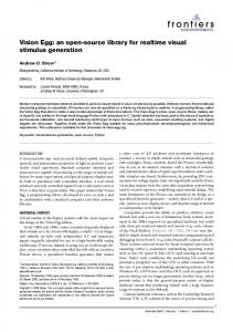
Paper Accepted for the International Conference on Power Systems (ICPS’07), Bangalore, India. December 12-14, 2007 Zero-crossing events cannot be accurately determined with fixed-step simulation schemes which make the detail simulation of high-frequency power-electronic control firing units practically impossible. A supplementary blockset, RTEVENTS, containing a rich library of logical functions, enhances the accuracy of fixed-step Simulink-based simulations by using interpolation methods now in used by several leading power electronic manufacturers. Finally, eMEGAsim comes with a special blockset that enables users to fully simulate and program the incorporated eMEGAsim FPGA board using the SIMULINK graphical block diagram interface, eliminating the need for VHDL programming knowledge. V. SIMULATION CAPABILITY Several examples of simulation cases, including HVDC, FACTS, industrial and hybrid-vehicles drives, are presented in [2] including the number of processors required for each application. Figure 5 [14], below, illustrates an example of a model simulated by eMEGAsim in real-time with 8 processors at 50 microseconds. It includes 8 wind turbines, modeled in great detail at the switching level, connected to a large power grid.
[5]
[6]
[7] [8]
[9]
[10]
[11] [12]
[13]
[14]
6
Controller Tests and Validation," in Proc. 2006 IEEE International Symposium on Industrial Electronics, pp. 2591 – 2596 S. Abourida, C. Dufour, J. Bélanger, T. Yamada, T. Arasawa, "Hardware-In-the-Loop Simulation of Finite-Element Based Motor Drives with RT-LAB and JMAG," in Proc. 2006 IEEE International Symposium on Industrial Electronics, pp. 2462 – 2466 C. Dufour, J. Belanger, S. Abourida, V. Lapointe, "FPGA-Based RealTime Simulation of Finite-Element Analysis Permanent Magnet Synchronous Machine Drives," in Proc. 2007 IEEE Power Electronics Specialists Conference, pp. 944 – 950 Opal-RT Technologies, RT-LAB Orchestra, www.opalrt.com/productsservices/softwarecomponents/orchestra/index.html S. Abourida, C. Dufour, J. Bélanger, G. Murere, N. Léchevin, B. Yu, "Real-Time PC-Based Simulator of Electric Systems and Drives," in Proc. 2002 IEEE Applied Power Electronics Conference and Exposition, pp. 433-438. L.-F. Pak, M. O. Faruque, X. Nie, V. Dinavahi, "A Versatile ClusterBased Real-Time Digital Simulator for Power Engineering Research," IEEE Trans. Power Systems, vol. 21, no. 2, pp. 455-465, May. 2006. L.-A. Dessaint, K. Al-Haddad, H. Le-Huy, G. Sybille, P. Brunelle, "A Power System Simulation Tool Based on Simulink," IEEE Trans. On Industrial Electronics, vol. 46, pp. 1252-1254, Dec. 1999. SimPowerSystems, User’s Guide, Version 4, The MathWorks Inc., 2006. C. Dufour, J. Bélanger, “Discrete Time Compensation of Switching Events for Accurate Real-Time Simulation of Power Systems”, in Proc. 2001 IEEE Industrial Electronics Society Conference, pp. 1533-1538. C. Dufour, J. Bélanger, "Real-time Simulation of a 48-Pulse GTO STATCOM Compensated Power System on a Dual-Xeon PC using RTLAB," Proceedings of the International Conference on Power Systems Transients (IPST 2005), Montréal, Canada, June 19-23, 2005 J.-N. Paquin, J. Moyen, G. Dumur, V. Lapointe, "Real-Time and Offline Simulation of a Detailed Wind Farm Model Connected to a Multi-Bus Network," in Proc. 2007 IEEE Electrical Power Conference, 8 pp.
VIII. BIOGRAPHIES Jean Belanger is President and co-founder of OPALRT Technologies. An expert in real-time simulation, with over 25 years of industry experience with the simulation division of Hydro-Quebec and IREQ, he has contributed to the development of the world’s first 735 kV power transmission systems and to the design of the world’s largest hybrid simulators and HYPERSIM digital real-time simulators. He has also worked a consultant on a number of high-voltage transmisson system projects worldwide. Mr. Bélanger received his M.Sc. from Laval University, Quebec and has been a fellow of the Canadian Academy of Engineering since 2001. Figure 5. [14] Model of a 24-bus electrical network incorporating eight wind generators. The model is distributed on eMEGAsim’s dual Intel® Core™2 Quad processors (8 CPUs).
VI. CONCLUSIONS High-end real-time power system simulators incorporating off-the-shelf supercomputer technologies are now affordable and commercially available. A number of power electronic equipment manufacturers are using eMEGAsim simulators similar to those presented in this paper. VII. REFERENCES [1] [2] [3]
[4]
EMTP-RV, www.emtp.com/software/emtp_rv.html Opal-RT, Power System Real-time simulation examples, www.opalrt.com/productsservices/electrical/index.html M. Harakawa, H. Yamasaki, T. Nagano, S. Abourida, C. Dufour and J. Bélanger, "Real-Time Simulation of a Complete PMSM Drive at 10 us Time Step," Proceedings of the 2005 International Power Electronics Conference (IPEC 2005), Niigata, Japan , April 4-8, 2005. C. Dufour, S. Abourida, J. Bélanger, "Real-Time Simulation of Permanent Magnet Motor Drive on FPGA Chip for High-Bandwidth
Vincent Lapointe is a simulation software specialist at Opal-RT Technologies. He received his M.A.Sc. degree from Laval University, Québec, in 2000. Since 1997, he has worked on the development of the realtime simulator RT-LAB and the RT-Events blockset. He is also team leader of the Electromechanical Systems R&D team (EMS). Christian Dufour is a Simulation Software Specialist at Opal-RT Technologies. In 2000, he received his Ph.D. degree from Laval University, Quebec. Before joining Opal-RT, he worked on the development of IREQ real-time simulators as well as the MathWorks’ SimPowerSystems blockset. His current research interests are mainly focused on numerical techniques related to real-time simulation of power systems and motor drives. He is the main author of ARTEMIS. Loic Schoen is Software Specialist at Opal-RT Technologies. In 1998, he received his Engineer diploma from the FIUPSO, Orsay, France. He is a specialist in real-time software and the team leader for the RT-LAB program.