proach for the support of model-based EIS engineering pro- cess using Zachman ..... per Network cells (Business row network cell in particular). The term site is ...
Proceedings of the 42nd Hawaii International Conference on System Sciences - 2009
Employing Zachman Enterprise Architecture Framework to Systematically Perform Model-Based System Engineering Activities Mara Nikolaidou, Anargyros Tsadimas, Nancy Alexopoulou, Dimosthenis Anagnostopoulos Department of Informatics & Telematics, Harokopio University of Athens 70 El. Venizelou Str, 176 71 Athens, Greece {mara, tsadimas, nancy, dimosthe}@hua.gr Abstract There are numerous Enterprise Information System (EIS) engineering methodologies in the literature, each covering different aspects. However, in order to integrate them in an Enterprise Architecture, model-based engineering can be adopted. In such a case, a central system model is defined supporting all engineering activities. Zachman’s matrix may be used as a basis for constructing such a model. Based on this assumption, we propose a systematic approach for the support of model-based EIS engineering process using Zachman matrix as EIS central model. Basic EIS engineering activities and the way they may be served by specific rows is explored, while the contribution of each system aspect (matrix column) is also taken into account. A conceptual model for model-based EIS engineering is also introduced. To explore the proposed concepts in practice, the System Network cell is used as an example. Corresponding engineering tasks and sub-models are formed based on the proposed guidelines in a technology and methodology independent fashion. A case study based on the proposed concepts is also presented.
1. Introduction Enterprise Architecture (EA) frameworks ( [19], [24]) are characterized as an attempt to integrate strategies, processes, methods, models and tools towards enterprise information system engineering [1].There are a lot of EIS engineering methodologies in the literature [8], each of them covering specific EIS engineering aspects. However, in order to integrate all of them in practice, the support of different system models cannot be avoided. In many cases, these models are not compatible, or even not known to others. The desired integration of people, strategies, processes, methods, models and tools could be accomplished by adopting model-based EIS engineering (MB-EISE). In such a
case, a central system model must be defined capturing all system requirements and decisions that fulfill them at different levels of abstraction. Since central system model serves all engineering activities, it should be technologyneutral, multi-layered, modular and composite, facilitating the integration of system sub-models corresponding to different perspectives and their progressive refinement. Relevant methodologies and tools addressing discrete engineering issues may be applied to specific system sub-models. In [20], the concept of using Zachman framework [25] as the basis for establishing a central EIS model for MBEISE was introduced. As such, Zachman matrix serves as a canvas to integrate different concerns, issues and methods towards MB-EISE, while specific methods may use parts of it as a reference point. We also identified some basic guidelines individual model-based methodologies should fulfill in order to be integrated into the Zachman matrix, focusing on how to establish the EIS sub-model corresponding to each of them. In an effort to apply these concepts in practice in a large scale organization, it became clear that the process of effectively forming the central EIS model was a complex one, while one of the main obstacles identified was the lack of a common understanding of the purpose of the central model by different stakeholders involved in EIS engineering. This resulted in EIS sub-models, which served well individual methods corresponding to them, but had poor interoperability since it was unclear how specific methods should be interrelated. To further establish the perception of MB-EISE based on Zachman framework, in the following we identify primary EIS engineering activities and explore the way they can be supported by specific Zachman matrix rows and columns resulting in an first level approach describing model-based EIS engineering process. To this end, we propose: (a) a first-level description identifying the primary EIS engineering activities served by Zachman matrix rows. (b) a conceptual model for MB-EISE according to
978-0-7695-3450-3/09 $25.00 © 2009 IEEE
1
Proceedings of the 42nd Hawaii International Conference on System Sciences - 2009
ANSI/IEEE 1471 standard [13], which may assist designers to formulate the central EIS model. (c) a common, first-level description of MB-EISE activities performed based on each cell-related view. Each of these activities consists of specific tasks that may be implemented by a specific EIS engineering method. Special attention was paid on defining EIS views and viewpoints for each cell in order to enhance information exchange between them. To explore the proposed concepts in practice, the System Network cell of the Zachman matrix is used as example, already discussed in [20]. Model-based EIS architecture design is focused in this cell. EIS architecture design activity is described based on common first-level MB-EISE activity model proposed. Identified tasks may contribute to related individual method and tool integration. System Network meta-model is adjusted to support individual EIS architecture design tasks and enhance inter-cell communication. The experience obtained when applying the proposed concepts during the renovation of the legacy system of a public large-scale organization is also discussed. The rest of the paper is organized as follows: Section 2 summarizes model-based EIS engineering based on existing standards and frameworks. In section 3 the way MBEISE process may be systematically supported by Zachman framework is explored. MB-EISE activities are identified, while a conceptual model for MB-EISE process is proposed. Section 4 explains how the main concepts of the proposed approach can be applied in identifying engineering tasks and EIS views for EIS architecture design performed within System Network cell. In section 5, a case study is presented to discuss the experience obtained when applying the proposed concepts. Conclusions and future work are discussed in section 6.
2. Background - Model-based EIS Engineering System engineering is defined as “an interdisciplinary approach and means to enable the realization of successful systems” [16]. Model-based system engineering (MBSE) is about elevating models in the engineering process to a central and governing role in the specification, design, integration, validation, and operation of a system. In such a case, activities that support the engineering process are to be accomplished by developing models of increasing detail [8]. Consequently, model-based EIS engineering can be defined as “the process of specifying, designing, integrating, validating and operating an Enterprise Information System based on the development of a central model, which can be extended in different levels of increasing detail”. This process is based on a process model that defines the primary activities that must be performed to ac-
complish EIS engineering. Each engineering primary activity [17], for example system design, may be further decomposed to more specific tasks in different levels of detail. A method is used to identify the way such tasks should be performed, while tools may contribute to the accomplishment of specific tasks/subtasks based on a specific method. The way EIS engineering tasks, methods and tools are integrated leads to different engineering methodologies. There is no point in attempting to construct a holistic methodology for EIS engineering due to the diverse nature of the issues explored and the increased complexity. However, the adoption of MBSE leads to the progressive construction of a central EIS model, independent of specific methodologies and tools, addressing all engineering activities in different levels of detail. The central EIS model can be defined as a collection of views and corresponding viewpoints, according to ANSI/IEEE Std 1471 [13], which provides a standard way of defining EIS models. It is efficient to define such a central EIS Model in practice? How many viewpoints are needed? How can it be ensured that all engineering activities are served by defined views? What is the level of description we should engage on? There is no unique methodology to address EIS engineering [8]. Furthermore, even well-established frameworks need further refinement [24]. We argue that trying to construct such a detailed model, accommodating all engineering tasks and discrete aspects of EIS, for example functionality, architecture, enterprise goals etc, is a pointless effort, due to increased complexity and diversity of issues, especially as the level of detail increases. Instead, one should provide a framework accommodating primary EIS engineering activities, which targets the integration and interoperability of discrete methodologies, tools and perspectives. Such a framework should identify all aspects and perspectives of EIS and be technology-neutral. Furthermore, it must provide EIS viewpoints and corresponding views, define rules for their interrelation/interaction and at the same time facilitate modelbased exploration of discrete EIS engineering issues using specific methodologies and tools in different levels of detail within corresponding views. Enterprise architecture (EA) frameworks may serve toward this direction. An overview of existing EA frameworks can be found in [11] and [19], while a wide discussion on Enterprise Architecture lays on [24]. Enterprise architecture discipline focuses on a holistic view of the Enterprise targeting at documenting the evolution of all enterprise aspects in order to fulfill its goals. EA frameworks facilitate modeling of all enterprise aspects and perspectives. Thus, they may serve for MB-EISE as well, while in this case we focus on the integration and formal communication of models, rather than the extensive description of all enterprise aspects targeted by EA efforts. We argue, that Zach-
2
Proceedings of the 42nd Hawaii International Conference on System Sciences - 2009
man framework could be most suitable for establishing a central EIS model for MB-EISE [20]. As indicated in [24] and [9], Zachman framework is the most popular EA framework, while many of the other ones are based on it. Most of them usually emphasize in specific issues, but they do not introduce new perspectives or system aspects. Furthermore, Zachman framework is technology-neutral. A plethora of methodologies and formalisms exist ( [6], [9], [22], [7]), each applicable to some subset of cells, while respective system models are defined.
3. Using Zachman Matrix to accommodate MB-EISE Activities Zachman framework provides a holistic model of enterprise information infrastructure. We argue that each matrix row may serve model-based implementation of a discrete primary engineering activity, as defined in [17] and proposed by INCOSE [16], addressing the needs of corresponding stakeholders. (see figure 1). The first two rows, namely Scope, denoting business purpose and strategy, and Business Model, describing enterprise functionality, are intensively business-oriented and are expressed in business oriented vocabularies [24]. They may serve two discrete primary EIS engineering activities, namely Defining Enterprise Objectives and Establishing Enterprise Functionality respectively. Definition of Enterprise Objectives may comprise specific activities, such as Policy Management, Enterprise Environment Management, Investment and Risk Management, and others characterized in IEEE 15288 as enterprise processes [17]. Establishing Enterprise functionality focuses on describing the provided services and corresponding requirements imposed by different stakeholders. The third row, namely System Model, which delineates how the system will satisfy the requirements yielding from business objectives, may serve EIS Design (both at software and hardware level). EIS Design facilitates requirements analysis and architectural design of both applications/data and EIS architecture. The next two rows, namely Builder Model, representing how the system is implemented and Out-of-Context including implementation-specific details, may serve Implementation and Detailed Implementation respectively [16]. The last row, Operational, which is the functioning system, may serve Support and Maintenance activities, also included in EIS engineering cycle. All primary engineering activities, as described in figure 1, are interrelated and recursively executed, since EIS engineering is an iterative process targeting the continuous improvement of EIS [16]. Model-driven implementation of these primary engineering activities based on Zachman matrix rows, accommodates the concurrent execution of them based on the EIS sub-model of the corresponding row, provided that they may obtain the informa-
Figure 1. MB-EISE primary activities based on the Zachman framework
tion needed by other Zachman matrix rows. Such an approach also facilitates the progressive engineering of EIS in different levels of detail, performed in cumulative cycles. Rules governing the Zachman framework, as defined in [25], are applied during model-based EIS engineering as well. EIS sub-models corresponding to each row are interrelated. The respective requirements are progressively refined starting from enterprise objectives to the functional EIS supporting it. Each primary engineering activity should be explored taken into account related requirements identified by the respective stakeholders. A requirement denotes a capability or condition that must (or should) be satisfied and may specify a function that a system must perform or a condition a system must achieve [3]. Thus, requirements are divided into two main categories, i.e. functional and nonfunctional [5], [18]. The Zachman matrix consists of 6 different rows, identifying EIS different aspects, each of which reveals different requirements related to the specific aspect. We argue that for each primary engineering activity, six different EIS viewpoints should be defined, each one related to a different EIS aspect. Data aspect describes the entities involved, while Function viewpoint shows how the entities are processed resulting to application implementation. Network viewpoint indicates where the entities are located resulting to EIS architecture. People viewpoint indicates users related aspects, while Time viewpoint reveals the way identified entities are synchronized. All these viewpoints are used to explore functional requirements, which are related
3
Proceedings of the 42nd Hawaii International Conference on System Sciences - 2009
to the functionality of the system. Non-functional requirements is a broadly used term. However, there is no consensus about the nature of non-functional requirements since various classifications of them exist in the literature [5] [18]. We believe that the basic aspects of non-functional requirements can be depicted in three sub-categories, namely performance, constraint and specific quality in accordance with other researchers [10]. The Motivation row of Zachman matrix relates to the reasons that lead to the specific functionality of an EIS. We argue, thus, that not-functional requirements should be handled by the Motivation viewpoint. A similar approach was also suggested in [9].
3.1. EIS Viewpoint and View Definition The conceptual model for MB-EISE using Zachman matrix according to ANSI/IEEE 1471 standard is depicted in figure 2. Enterprise architecture is described by an EIS Engineering framework based on the Zachman matrix. As such, the framework focuses on 6 different perspectives serving discrete primary engineering activities according to Zachman matrix row rationale and 6 different aspects according to Zachman matrix column rationale. Thus, EIS engineering framework consists of 36 EIS views, defined according to the combination of perspectives and aspects. For each EIS view a viewpoint is defined serving the corresponding stakeholder’s perspective on a specific aspect. For example the Design Function Viewpoint serves application designer. EIS view defined by each viewpoint corresponds to EIS sub-model related to the specific cell, while the central EIS model is constructed by integrating all Zachman cell sub-models. Each aspect viewpoint (for example function) is treated independently within the limits of the specific engineering activity (for example design) based on a corresponding EIS sub-model, while specific methodologies and tools may be applied within EIS viewpoint corresponding to each Zachman matrix cell. For example, RUP methodology [7] could be employed for application design within System Function cell. To promote interoperability and integration, it is crucial to provide a typical definition of the meta-model describing each EIS view. In similar approaches, as in [9] which focuses on Zachman’s second row, although some ideas are discussed, no formal meta-model is given for the description of each cell. Since each view is treated autonomously, EIS sub-model describing it should contain all necessary information to perform the respective tasks. Therefore, both internal entities related to the specific engineering activity and external entities facilitating the integration with other cells, construct each view sub-model. External entities indicate the information needed by other cells, while they also indicate the information provided to other cells. Each cell view gathers information from all the cells of the same row (participating
in the same engineering activity) and the cells of the same column above and beneath it, while it also may pass information to them. Upper and lower cells participate in the progressive refinement of enterprise requirements for the specific aspect. EIS view integration and inter-view consistency is accomplished by creating mappings between external entities of respective models. The corresponding stakeholder is responsible for describing internal entities of each cell-related view. Each cell-related view may be further decomposed into EIS sub-views, focusing on specific issues. The corresponding stakeholder should be accommodated with a black-box (indicating requirements imposed by external factors) and a white-box (describing the proposed solution) perception of EIS aspects under study [7] [15]. All sub-views constructing an EIS view should be related. As indicated in [4], two basic relations are identified between views: refinement (the internal view refines the external view on a different level of detail) and complement (two views may complement each other by considering complementary concerns). Sub-views are defined according to theme-specific viewpoints refining the respective EIS viewpoint. For each EIS view, a corresponding representation model should be defined, along with the necessary mappings to EIS view sub-model. Independently of view definition meta-model, we suggest that UML [14] or SysML [15] should be adopted for EIS view representation, as they are very popular standards.
3.2. First-level Description of Basic MBEISE Activity The model-based EIS engineering activity corresponding to any Zachman cell should support the basic tasks depicted in figure 3. They could be cumulatively resolved at different levels of detail, facilitating the progressive solution of related engineering issues. The way they are implemented or further analyzed is methodology-specific. The task of collecting requirements task relates to the extraction of external information from other cells and the refinement of functional and non-functional requirements by the corresponding stakeholder. It can be served by multiple subviews, each of them grouping external entities related to different cells. The task regarding solution synthesis indicates the construction of alternative models to solve specific engineering issues. Solutions are consequently evaluated and optimized, while, based on evaluation results, both alternative solutions and imposed requirements may be adjusted. In the latter case, solutions synthesized in other cells (either in the same row or column) may be affected, while solutions suggested in different cells should be synchronized. This can be accomplished by communicating external entity values to the corresponding external cells. Thus, inter-
4
Proceedings of the 42nd Hawaii International Conference on System Sciences - 2009
described by
1
Enterprise Architectures
1 1 influenced by 1
described by
1..*
1
1
EIS Engineering Rationale defined
1
Central EIS Model
identifies
Enterprise Stakeholder
focusing on 1..6
*
*
Primary Activity Rationale Compatible to Zachman Rows
EIS Engineering Perspective
is served by
is important
1
1
EIS Engineering Framework
has
Extented Environment
follows
1
Enterprise
1..*
EIS Viewpoint
1 is served by 1..*
*
Concern
Defined according to the combination of Aspects and Perspectives
refined to 1..* 1
Theme/Specific Viewpoint relates to
EIS Aspect Rationale According to consists of Zachman Columns
EIS Aspect
describing
covers 1..* 1..*
consists of 1..6
1
covers 1
1..*
EIS View 0..*
1
1
1
defined
EIS Sub-model 1
0..* relate to
represented
1 describing
1 1
Viewpoint Library
EIS View Representation Model
1
relates to
consists of 1..*
EIS Sub-view
1..*
Model-Library
complement
Figure 2. MB-EISE conceptual model
4. Model-Based Enterprise Information Systems Architecture Design
Figure 3. Basic engineering tasks performed based on each cell-related view
operability between methodologies applied within each cell can be accomplished. These tasks should be further refined within the limits of each Zachman cell. Since, even within the purpose of a specific methodology or viewpoint, discrete issues may be resolved using autonomous, heterogeneous tools, tool integration related to a specific task should be supported. Some of them may employ their own internal model for EIS representation. Thus, tool coordination and internal meta-model transformation should also be supported. According to model-based engineering principles, consistency is ensured, since the EIS view meta-model acts as a “reference point”. Prior to using an existing tool, the partial transformation of view metamodel into the tool’s internal meta-model must be facilitated. Using this transformation, the invocation and initialization of any tool can be automatically performed.
To further elaborate on basic MB-EISE activity model refinement and the proposed guidelines for constructing EIS cell-related view and the interaction with external cells, the System Network cell of the Zachman matrix is used as example. According to INCOSE [16], determining system architecture (i.e. the way autonomous system components should be synthesized) is a complex process. EIS architecture design is the process of defining and optimizing the architecture of the information system (both hardware and software) and exploring performance requirements, ensuring that all software components are identified and properly allocated and that hardware resources can provide the desired performance. This activity is performed based on the EIS view corresponding to system network cell, which should facilitate: (a) definition of EIS architecture (e.g. a system-oriented view of distributed applications), (b) definition of system performance and availability requirements, (c) definition of system access points, (d) description of platform-independent distributed infrastructure (e.g. network architecture and hardware configuration) and (e) association of software components to network nodes (resource allocation), in order to ensure performance and availability requirements. EIS architecture design was also discussed in [20]. In the following, we provide a methodology-independent, modelbased EIS enterprise design activity model and describe the corresponding EIS architecture design sub-views as well as
5
Proceedings of the 42nd Hawaii International Conference on System Sciences - 2009
Figure 5. EIS Sub-Views corresponding to the System Network cell
Figure 4. EIS Architecture Design basic engineering tasks
way they are interrelated to external cells.
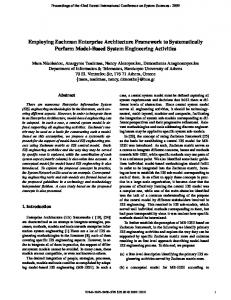
4.1. First-level Description of EIS Architecture Design MB Activity The basic tasks identified during the EIS architecture design activity are depicted in figure 4. These tasks are in alignment with basic engineering tasks performed for each Zachman matrix cell, as depicted in figure 3. Collect Requirements task (as depicted in figure 3) is accomplished through two discrete stages i.e. Functionality Definition and Requirements Definition within System Network cell. The former depicts functional requirements extracted from People, Data and Function cells of the system model row. The latter concerns non functional requirements related to EIS architecture design, extracted from the Motivation cell of System Model row. Requirements included in this cell are either propagated from the upper layers of Zachman framework or specifically defined for system design and may relate to issues not relevant to EIS architecture design. Only architecture design related requirements are propagated within EIS System Network view. Next, the solution is synthesized through two interactive steps i.e. Topology Definition and Network Infrastructure Definition ( [7], [12]). Topology Definition facilitates resource allocation and replication. This task is performed taken into account the definition of system access points in terms of hierarchically related locations performed in upper Network cells (Business row network cell in particular). The term site is used to characterize any location (i.e. a building, an office, etc.). As such, a site is a composite entity which can be further analyzed into sub-sites, forming thus a hierarchical structure. Network Infrastructure Definition refers to the aggregate network, described through a hierarchical structure comprising LANs. Devices, such as servers and workstations
are associated with LANs at the lowest level of the hierarchy. Network nodes are either workstations allocated to users or server stations running server processes. Topology and Network Infrastructure Definition tasks are interrelated. Both should be performed in the same hierarchical levels of detail. At the lowest level, network nodes should be related to processes/data replicas. In essence, interaction between these two tasks represents an interdependence in terms of derived requirements. Requirements derived during Topology Definition affect Network Infrastructure Definition and vice versa. Therefore, Requirements Definition is performed in parallel with Topology and Network Infrastructure Definition as well. Developing requirements and architectural artifacts in parallel has already been addressed in the literature [23]. After the solution deployment, validation is performed using simulation. Solution evaluation will determine whether the overall process will end in case the solution is satisfied or readjustments will be performed through the recurrence of the previous steps. The tasks of figure 4 corresponding to Requirements Collection and Solution Synthesis (which presented in figure 3) are described through a discrete view. As such, four relative views are defined, namely, Functional View, Topology View, Network Infrastructure View and Requirements View. These views constitute sub-views of the SystemNetwork view of Zachman framework. Solution validation and evaluation is performed using information included in all of them. Interrelations between corresponding tasks are reflected upon the introduced views. These interrelations along with the dependencies between the introduced views and the related models of the corresponding Zachman cells are depicted in figure 5. Dependencies with external Zachman cells are bidirectional. Functional view obviously is influenced by and influences People, Data and Function cells of System Model row, while Requirements view interacts with System Motivation view. Topology view is bidirectionally related to Business Network view, while Network Infrastructure view to Technology Network view. System Network views are illustrated in figure 5 in a blackbox manner. A white-box perspective of them will unfold through the description provided in the following para-
6
Proceedings of the 42nd Hawaii International Conference on System Sciences - 2009
graph, further elucidating view interdependencies.
4.2. Meta-model describing System Network View The meta-model of System Network view, e.g. entities constituting each sub-view and their interrelations, is adjusted to support the identified tasks. As depicted in figure 6, Functional view encompasses functional requirements derived by external system cells. It focuses on functional specifications (e.g. application architecture, user behavior and data structures). Applications are considered to be based on multi-tiered, client-server models. Each application tier, called module, comprises services. Application tiers and provided services should be in accordance to the model defined in Function cell, thus they act as external entities. User behavior is modeled through roles defining the behavior of different user groups. They act as external entities for People cell (e.g. they could be related to user role entities). Data entities are defined to indicate portions of data used by applications. They also act as external entities for Data cell. For each service, a service description sub-view is defined indicating network infrastructure resources needed for its execution. The load imposed to network infrastructure resources each time the service is executed is expressed using operations selected from a predefined set called Operation Dictionary [21]. Service Description and Operation Dictionary sub-views will be further described latter after discussing Requirements view. Topology view facilitates allocation of software, data and people resources. It comprises sites, defined in upper Network cells, processes defined as instances of server or client modules, user profiles as instances of roles, and data entity replicas as instances of data entities defined in Functional View. The allocation of them to sites corresponds to software architecture design. Sites are organized in a hierarchical structure. Those belonging to the lowest level of the hierarchy are characterized as atomic. Network Infrastructure view comprises the overall network decomposed to sub-networks. Devices, such as servers, workstations and other network devices are associated with LANs at the lowest level of the hierarchy. Devices may include a processing unit and a storage unit. Networks and network nodes are characterized by capacity indications, for example throughput, storage speed or processing power, which should be matched with load requirements, related to Topology view entities. As a result, networks are associated to sites defined in Topology view, while processes, data entity replicas and user profiles located in atomic sites are allocated to server or workstation devices included in the corresponding LAN. Requirements view comprises non-functional requirements derived from the System Motivation cell relevant to
EIS architecture design or progressively defined during the execution of the EIS Architecture Design tasks. Requirements defined within requirement view are satisfied by specific entities included in Functional, Logical and Network Infrastructure views and contribute to inter-view interrelations. In the following we provide a further classification of non-functional requirements based on our objectives in respect to EIS architecture design. Three main categories are supported: performance, constraint and specific quality [10]. Regarding constraint requirements, we focus on those concerning capacity. Capacity, which has to do with the limitations of the hardware and their impact to the system, is related to Network Infrastructure view. Regarding specific quality requirements, we consider only availability requirements. They are associated with Network Infrastructure view, where availability deals with hardware aspects. Availability requirements may be either derived from upper level requirements, within System Motivation cell, or defined with System Network cell during EIS architecture design. Requirements defined within System Network cell during EIS architecture design should be passed to EIS System Motivation view. As depicted in figure 6, performance requirements are further decomposed to behavior, load and utilization. Utilization requirements are associated with Network Infrastructure view and regard the proportion of network infrastructure resources used by applications during normal operation or extreme conditions. Behavior requirements deal with service behavior and are time-related (e.g. response times). They affect Functional view, as indicated in figure 6. Load requirements concern the load imposed to EIS resources by system entities, as processes and data replicas, defined in Topology view, for example average data transfer load or data processing load imposed by a specific process. These requirements are derived ones, which should be calculated for execution of each specific service based on behavior requirements and service decomposition described in Service Description sub-view. The execution of each service relates to specific load requirements imposed to network infrastructure. To identify such requirements the amount of information processed, stored or transferred during its execution should be estimated. The Service Description sub-view is introduced for this purpose, defined for each service included in Functional view. Since service functionality can be complex, it is not easily described in terms of the amount of information processed, stored or transferred during its execution. To facilitate the progressive estimation of load parameters, a set of operations are defined for the description of service load requirements [21]. Operations are selected from a predefined set defined in Operation Dictionary sub-view, which comprises application and elementary operations. Application
7
Proceedings of the 42nd Hawaii International Conference on System Sciences - 2009
Functional View Service Description Sub-view Requirements satisfied by Functional View
Transition
Role
Invoke
-source Initiate
-outgoing
-source -target1
1 Application
-incoming
1
Module
Requirement View
-target
Operation Activation
Behavior
Functional
Derive -source
Service 1
Operation
-outgoing
-target
Load
Operation Dictionary Sub-view -incoming
Data Entity 1..*
1
-incoming
-source
Service Description
-target
-outgoing -incoming
-outgoing
Performance -target -source
Call
-outgoing
Utilization
-incoming
Requirement
1 Network Infrastructure View -source1
1..*
-outgoing1
Invoke
1
-incoming1 1..* 1..* Process
-target
-outgoing1
Initiate
Constraint Non-Functional
Node
1
1..*
-source
Capacity
Workstation
Data Entity Replica
Network
Availability
Specific Quality
1 Server
Site
1
Network Device
-incoming 1
-target
Requirements satisfied by Network Infrastructure View
User Profile Processing Unit 1
Storage Unit
Topology View
Requirements satisfied by Topology View
Figure 6. EIS System Network View Meta-model operations are those used for service description and must be ultimately decomposed into elementary ones (i.e. data processing, storing and transferring). Load requirements are estimated through parameter values that are propagated by service invocation parameters to parameters describing application operations constituting the service description, which are further propagated to parameters describing elementary operations.
4.3. EIS Architecture Design Task Implementation EIS Architecture Design tasks may be supported by existing tools [20]. Systems Modeling Language (SysML) [15] is considered as the most appropriate for EIS System Network model representation and requirement engineering, since it supports the concepts of requirements and resource allocation. As a direct consequence, SysML allows the representation of requirements as model elements, which means that requirements are part of the system architecture. For representation purposes, a SysML profile for EIS System Network meta-model (figure 6) is being implemented as a plugin to MagicDraw modeling tool [2]. In order to facilitate model exchangeability, EIS System Network model is being realized in XML, which is a standard exchangeable format. In order to exchange data with specific software tools, model transformations will be accomplished through appropriate XSLTs developed for each tool, for example as the one transforming XMI to the EIS System Network document type description (DTD) and vise-versa.
5. Case Study In the following we discuss the case of renovating a legacy information system supporting a large-scale public organization based on the proposed concepts. The organization supports more than 350 interconnected regional offices and its main purpose is to provide services to the public, both citizens and businesses. Regional offices are divided into three categories according to their size and information infrastructure requirements (large, medium and small). More than 15.000 employees work in the organization having on-line access to the legacy system. There are more than 300 different services provided to the public, while each citizen is required to register in the one belonging to his/her residential area, called residential office. Some of them require the actual presence of citizens in their residential office. Existing system architecture is based on a fat clientserver architecture. All application logic is programmed within the client platform, while data is distributed in local database servers located in each regional office. A Central database is supported in the Datacenter for data synchronization and lookup purposes. The Datacenter and all regional offices participate in a private TCP/IP network to facilitate efficient data replication. Most data related to a specific citizen are maintained as local data in his/her residential office. Client programs access the local database to store data, while they access the central database mostly for lookup purposes. Local data are asynchronously replicated in the central database using a transaction management system (TMS). TMS clients are installed in client workstations
8
Proceedings of the 42nd Hawaii International Conference on System Sciences - 2009
to facilitate communication with the central database. The central database provides the overall view of each citizen’s record. To enhance the level of services provided by the organization, we decided to establish an enhanced e-services environment through an e-government portal. The main target of the portal is to minimize the need for citizen’s presence in regional offices and intents to deal with all the drawbacks of the current e-service platform. It provides easy access to citizens and businesses twenty four hours per day, seven days per week. It also promotes the increase of e-services to users, facilitating the organization to accomplish its strategic goals. The portal facilitates on-line transactional services and ensures on-line access to the databases of the legacy information system. Provision of transactional e-services reflects the operation of the legacy system and thus results in its renovation. In order to effectively support both systems (e.g the portal and the legacy system), the organization should be able to apply the same policies and minimize maintenance cost. Thus, it was decided to explore the renovation of the legacy information system by adopting modern technological trends, such as multi-tiered application architecture, server-based computing and light clients. It was decided also to rewrite application code based on J2EE architecture to develop a web interface for the legacy information system in order to support a unified environment for both the legacy system and the portal. This decision affected the legacy system architecture, described in System Network View. Some of issues raised included: (a) Should there be a change in the database architecture? It is currently distributed. Should it become centralized? What are the implications in the network infrastructure? (b) Can hardware consolidation be accomplished to minimize maintenance cost? Though EA was never fully described, the organization had already decided to establish an EA based on Zachman framework a few years ago. RUP methodology was used for software development, thus application description models were developed within Rational Rose platform. In order to be able to apply the proposed tasks identified in section 4, relative information had to be extracted from the corresponding cells. Application description (e.g. applications and modules) as well as data structures were manually extracted from corresponding Rational Rose files. Though the process was not automated, the provision of System Network meta-model, helped architecture designer to identify the information needed to obtain from software designers. Detailed service description in terms of load requirements could not be extracted from software description. This was crucial in order to decide upon Intranet and Datacenter architecture. This information was collected by interviewing software developers. The new system has to deal with a number of require-
Organization
Small Regional Office
Medium Regional Office
Large Regional Office Central Organization Building
L.R.O. department
Datacenter server room
R.O. server room
oracle net
officer
Oracle Central database
oracle L.R.O.
tuxido Central
application
tuxido L.R.O.
tuxido
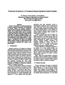
Figure 7. Topology View - Existing System ments, with security and availability being the most important ones. Security issues have to do with the security of the network, security of data, authentication control, etc. Availability requirements deal with the backup subsystem, the recovery system and high availability UPS. Privacy must be enforced with the use of cryptography and compression techniques. All these requirements were identified during the System Architecture design process and consequently exported in System Motivation cell where all system requirements are gathered using a simplified text-based requirement description method. System Architecture design tasks were performed by existing tools already described in [20]. The existence of System Network meta-model and its implementation in XML facilitated tool integration and interoperability. The identification of primary EIS engineering activities served by Zachman matrix rows and columns facilitated a better understanding between software developers, architecture designers and organization management and enhanced discrete methodology integration. Existing and renovated application architecture of the legacy system defined by Topology View are presented in figures 7 and 8 respectively. The screenshots are from the MagicDraw [2] tool, enhanced with EIS profile to provide the appropriate functionality.
6. Conclusions & Future Work MB-EISE process based on Zachman framework was explored in the paper. The designer may adjust basic MB-EISE activity model for each cell, formulate a methodology-independent EIS cell-related view, and finally identify methods and tools appropriate for implementing each specific task. One could argue that in such a case, 36 distinct EIS sub-views should be defined, each of them being rather complex, while basic MB-EISE activity should be adjusted 36 times, resulting in a very complicated process.
9
Proceedings of the 42nd Hawaii International Conference on System Sciences - 2009
Organization
Small Regional Office
Medium Regional Office
Large Regional Office
Central Organization Building
L.R.O. department
Datacenter server room
Web Server
officer
web browser
Oracle Central database
Oracle Application Server
Figure 8. Topology View - Renovated System However, EIS engineering process, as enterprise architecture, is itself complex. The benefit of the proposed approach is that all aspects (simple or complex) are handled in a uniform and modular fashion. Cell-related sub-views and corresponding meta-models, as well as cell-related MB-EISE activity model may be progressively formed according to the designer’s priorities and perspectives. Having a black-box view of each Zachman cell, the proposed approach focuses on EIS view integration and interview consistency. The notion of external entities when defining EIS cell-related views provides the means for interoperability with external cells, while at the same time facilitates atomicity within the limits of each cell. We are currently emphasizing Business and System rows, and especially Function and Network cells, exploring in parallel Motivation column and the way non-functional requirements are managed. Having a white-box view of each Zachman cell, it is evident that the definition of a technology neutral metamodel and the identification of basic engineering tasks, corresponding to EIS cell-related views, contributes to the integration of different methodologies and tools. A library of EIS System Network models has been already implemented in XML. Emphasis is given to requirements management and especially requirements derivation.
References [1] Institute For Enterprise Architecture Developments. http://www.enterprise-architecture.info/. [2] MagicDraw UML. http://www.magicdraw.com/. [3] A. Aurum and C. Wohlin. Engineering and Managing Software Requirements. Springer, 2005. [4] F. S. d. Boer, M. M. Bonsangue, J. Jacob, A. Stam, and L. W. N. v. d. Torre. A Logical Viewpoint on Architectures. In EDOC, pages 73–83. IEEE Computer Society, 2004. [5] E. R. Byrne. IEEE Standard 830: Recommended Practice for Software Requirements Specifications, 1998. [6] B. Dave and D. Jim. The new, improved RUP SE Architecture Framework, 2005. IBM Rational Edge.
[7] D. J. de Villiers. Using the Zachman Framework to assess RUP. Rational Edge, 2001. [8] J. A. Estefan. Survey of Model-based Systems Engineering (MBSE) Methodologies. INCOSE MBSE Focus Group, May 2007. [9] A. Fatolahi and F. Shams. An investigation into applying UML to the Zachman Framework. Information Systems Frontiers, 8(2):133–143, 2006. [10] M. Glinz. On non-functional Requirements. 15th IEEE International Requirements Engineering Conference, 2007. [11] F. Goethals, W. Lemahieu, M. Snoeck, and J. Vandenbulcke. An overview of enterprise architecture framework deliverables. In Banda RKJ (ed) Enterprise Architecture-An Introduction. ICFAI University Press., 2006. [12] H.-P. Hoffmann. Harmony-SE/SysML Deskbook: ModelBased Systems Engineering with Rhapsody, Rev. 1.51, Telelogic/I-Logix white paper. Telelogic AB, May 2006. [13] IEEE. IEEE Recommended Practice for Architectural Description for Software-Intensive Systems - Std 1471. Technical report, oct 2000. [14] O. M. G. Inc. UML 2.0 Superstructure Specification, October 2004. [15] O. M. G. Inc. Systems Modeling Language (SYSML) Specification. Version 1.0, September 2007. [16] INCOSE. INCOSE Handbook SE Process Model, September 2003. http://g2sebok.incose.org/. [17] Institute for Electrical and Electronic Engineers. IEEE Std 15288 -2004, Systems Engineering -System Life Cycle Processes, June 2005. [18] A. v. Lamsweerde. Goal-Oriented Requirements Engineering: A Guided Tour. In Fifth IEEE International Symposium on Requirements Engineering (RE’01), page 249, aug 2001. [19] S. Leist and G. Zellner. Evaluation of current architecture frameworks. In H. Haddad, editor, SAC, pages 1546–1553. ACM, 2006. [20] M. Nikolaidou and N. Alexopoulou. Enterprise Information System Engineering: A Model-Based Approach Based on the Zachman Framework. In HICSS’08. IEEE Computer Society, 2008. [21] M. Nikolaidou and D. Anagnostopoulos. A systematic approach for configuring web-based information systems. Journal of Distributed and Parallel Databases, 17(3):267– 290, May 2005. [22] C. M. Pereira and P. Sousa. A method to define an Enterprise Architecture using the Zachman Framework. In H. Haddad, A. Omicini, R. L. Wainwright, and L. M. Liebrock, editors, SAC, pages 1366–1371. ACM, 2004. [23] K. Pohl and E. Sikora. Supporting the Co-Design of Requirements and Architectural Artifacts. In 15th IEEE International Requirements Engineering Conference (RE’07), pages 258–261, India Habitat Center, New Delhi, 2007. [24] J. Schekkerman. How to Survive in the Jungle of Enterprise Architecture Frameworks: Creating or Choosing an Enterprise Architecture Framework. Trafford, 2003. [25] J. F. Sowa and J. A. Zachman. Extending and Formalizing the Framework for Information Systems Architecture. IBM Systems Journal, 31(3):590–616, 1992.
10