channel-controlled disk search to find a given record key.) The order of state ..... variable-length records per track, where records are addressed by track and ...
Emulator Architecture Efrem G. Mallach Honeywell Information Systems Inc.
I ntroduction Upgrading to a newer data processing system is not simply a matter of removing the old equipment and plugging in the new. The older system's workload must be transferred to the newer one-and the newer one is usually also a fundamentally different one. The effort involved in such a conversion is massive. The difficulties of obtaining a smooth transition from one machine to the next are immense. There are a number of ways to approach this conversion, and they all have drawbacks. Use of higher-level languages eases the transition, but today these are neither universally standardized nor always appropriate, and they do not address the area of data compatibility.2' Automatic program translators' ' are useful, but historically they have approached complete translation only between very similar architectures-for example, IBM 1401 to Honeywell Series 24
200/2000.3 Hand translation is both time-consuming and expensive. A tool that has proven useful during the conversion process is called emulation. Emulation involves building or modifying a computer system to execute programs written for another system, in addition to its own programs. With such a tool-an "emulator"-a user can initially run old programs, converting them at leisure to the native mode* of the new system. The conversion process is, thus broken *We assume that the native mode of the new system is known. It can be informally characterized as the mode(s) which the manufacturer recommends for new applications. Our use of this concept allows for systems having many "native" instruction sets, each designed for a different application area, and for systems designed to be programmed exclusively in higher-level languages. While attempts to define "native mode" rigorously for all cases can usually be defeated by counter-example, a user faced with a specific system seldom has any difficulty defining it in practice.
COMPUTER
down into two stages. The first, from the old hardware to the new, is greatly simplified since virtually no program modification is involved. The second, from the emulator to the new system's native mode, is under reduced time pressure. Note that, strictly speaking, the emulator is not a conversion tool. It is, rather, a tool for postponing conversion, so that the conversion proper can be performed in an orderly fashion. The user of an emulator normally plans on eventual complete conversion, so as to take advantage of the full hardware and software capabilities of the new system. This paper gives a historically oriented tutorial view of how emulators have been built. We begin with a general definition of emulation. The following section gives a technical overview. The emulation of central processor operations is covered next, with particular reference to microprogramming, and emulation of input/output operations is the final topic. Our objective here is to provide the reader with an understanding of the problems encountered in developing an emulator, of the way these problems have been approached in the past, and of the tradeoffs involved. We will not emphasize any particular emulator, and will refer to specific ones only as examples. An emulator may be defined as hardware, microprograms, and software added to one computer system to enable it to execute programs written for another system. Any of these components may be absent in a specific case, but as a minimum, either added hardware or added microprograms must be present. (Without one of these, we say we have a simulator.) Certain authors (e.g., Rosin26 and Lesser'9) use the term "emulation" in a different sense. To them, it is synonymous with the implementation of any instruction set using microprogramming technology. Thus, they would refer to the IBM 360/50 "emulating" the 360. This definition will not be used for three reasons: (1) because it is at variance with the original IBM use of the term, which is today accepted for general-purpose commercial computer systems by all major manufacturers; (2) because it would leave us with two ways of referring to one useful concept and no way of referring to another one; and (3) because we wish to separate the functions of emulation from the choice' of a technology to support them, however attractive a particular one may be today. Both meanings have their place. For example, it is much more convenient to say "the 360/50 emulates the 360" than to say "the 360/50 implements the 360 instruction set through microprogramming." The reader should expect to encounter both senses in the literature. The purpose in explaining the distinction is to clarify the use of the term in this paper. For a historical survey (until mid-1972) and overview of emulation, see "Emulation: A Survey" by Mallach.2° Specific emulators are discussed at an introductory level by Benjamin,4 Bowman and DeSchon,5 Franks and Warren,'0 McCormack, Schansman and Womack,22 Schoen and Belsole,28 and Tucker.30 Computers designed for emulation flexibility are described by Lawson and Smith,'8 Rackoczi,24 Reigel, Faber and Fischer,25 and Rosin.26 Two general papers are "System/370 Integrated Emulation under OS and DOS" by Allred,2 which emphasizes integrated emulation, and "Emulations Systems" by Tucker,3 2 written for an audience of microprogrammers not especially familiar with emulators.
August 1975
Technical Overview As mentioned above, an emulator typically comprises three parts, though some may be absent or trivial in a particular instance: hardware and firmware* additions to the central processor, software in the central processor, and modifications to input/output subsystems. The hardware and firmware additions to the central processor have received the bulk of the attention given to emulators in the literature. These additions always perform the most heavily used portions of instruction execution. Beyond that, their functions depend on the tradeoffs in a specific situation. In one case (IBM 1401 on 360/3022), the added hardware and firmware also execute I/O operations, but this is rare and is limited to emulated systems with the simplest of I/O command structures. Software in the host computer is used to fill whatever gaps are left by the hardware and firmware. These gaps may exist in the execution of I/O instructions, the execution of infrequently used non-I/O instructions, and emulator control (including control panel operations). I/O subsystems are modified for emulation when a subsystem's original design will not support the emulated I/O operations, or when adequate performance cannot be obtained if these operations are simulated purely by software. The trend today is toward increasing use of I/O subsystem changes. While this paper will concentrate on central processor hardware, firmware, and software, it will note areas where subsystem modifications can be helpful.
Central Processor Instructions Historically, three approaches have been used in emulating central processor instructions. The first calls for hardware or firmware assistance to a software simulation of these instructions, as in the IBM 360/65 emulator of the IBM 7090.3° The second involves complete execution of these instructions by host system hardware or firmware, as in the RCA Spectra/70 emulator of the RCA 301.4 The third calls for the attachment of an auxiliary processor to execute instructions of the emulated system. This paper will not discuss the auxiliary processor approach; it will take up the other two in the order given. Software-Controlled Emulation Using this approach, the designer first develops and analyzes (perhaps mentally) a software simulator of the target system. Certain instruction sequences will stand out as being very frequently used, as being awkward ways to perform inherently simple functions, or both. These sequences become candidates for hardware or firmware assistance. This assistance is provided by defining new instructions, each replacing such a sequence. These new instructions are implemented in the same way as the standard instruction set of the emulating processor. As Tucker3 0 points out, the first function so implemented is instruction fetch and analysis. The usual mnemonic for this emulator instruction is Do Interpretive Loop (DIL). The DIL begins by testing for pending *"Firmware"
is the physical realization of a microprogram. The term originated from the position of microprograms between hardware and software. Microprogramming is discussed in more
detail below.
25
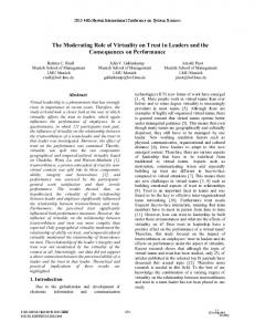
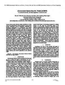
interrupts. In their absence, it obtains the contents of the emulated instruction counter from a fixed location, often a register. The location thus identified is presumed to contain an instruction, which is then fetched. DIL execution often also includes dividing the instruction into useful fields, calculating effective addresses in memory, and storing the information so developed in fixed locations. (For example, the IBM 360/85 emulator of the IBM 7094 leaves the effective address to be used by a 7094 memory reference instruction, properly aligned for 360 program use, in general-purpose register 3 of the 360.) The DIL concludes by giving control to a software routine which will simulate the execution of the instruction just decoded. The execution subroutine uses the information left by the DIL to simulate instruction execution. In so doing, it may be aided by further emulator instructions, which we may classify as follows: General utility instructions: these serve as effective subroutines for many simulation sequences. A typical function is converting data or addresses between the format of the emulated system and a format that is convenient for the emulator routines to use. An example is the ZACB instruction of the IBM 370/165 emulator of the IBM 7080, which converts a Zoned (i.e., decimal) Address to Coded Binary, so it can be used by 370 software. Partial execution instructions: these execute the bulk of the instruction to be simulated, but require setup, cleanup, or both. Examples are various "emulator branch" instructions, which require a prologue to establish testable conditions in the proper form, and then perform conditional branching functions. Complete execution instructions: These perform the entire execution phase of an instruction to be simulated. When one is applicable, the entire subroutine reduces to two instructions: the execution instruction, followed by a DIL to fetch the next instruction of the emulated program. An example is the ST09 instruction of the IBM 360/65 emulator of the IBM 7090, which emulates the entire execution phase of the 7090 STO (STOre) instruction. Two major tradeoffs can be identified in the development of these instructions. The first is how far to go with firmware. Figure 1 diagrams the decision process. First, software functions that are both frequently used and hard to simulate (the lower left corner of the figure) are placed in firmware. Functions that are increasingly easier to simulate in software, or that are decreasingly frequently used, are then microprogrammed until cost-performance factors or technical limits force a stop. This is indicated in the figure by the arrows radiating from the lower left corner. The second tradeoff is faithfulness vs. performance. Complete faithfulness is always possible in principle. Performance can often be improved, however, by restricting the emulation of programs which use unspecified features, which use non-recommended programming techniques, which depend explicitly on the absence of an option, etc. If the emulator developers can constrain the software to be executed on the emulator, even more severe restrictions may be acceptable-with even more performance gained as a result.
Firmware Controlled Emulation The implementor of a thorough software-controlled emulator will soon notice that this emulator can go through fairly long program sections while alternating between complete execution 26
instructions and DIL's. Under these conditions, maintaining a software skeleton to control this alternation serves no purpose in a production environment. The next step toward completeness is to have the branch at the end of the DIL go directly to a microprogrammed or hardware-implemented execution phase, rather than to software. The result of doing this is a firmware-controlled emulator.* In this type of emulator, control of the system while non-native instructions are being executed resides entirely in the hardware or firmwarei, much as if the system were executing the instructions associated with its native mode. The instruction execution speed achievable by this type of emulator can approach that which would be possible were the emulated system to be re-implemented in the technology of the host system. The actual performance achieved depends on the degree to which new data paths, arithmetic units, etc., are added to the host computer. Lower performance, though still exceeding that of a software-controlled emulator, is obtained when the designer adds control circuits or firmware to process data through the paths and functional units already present. The cost of building a firmware-controlled emulator is high compared to the previous approach, and varies with the required performance level. With this type of emulator, an instruction (or variation on an existing one) is added to the emulating system to enter emulation mode. Before the emulator is activated, initial values of the emulated program counter and other registers are placed in known registers or memory locations. Once emulation mode is entered, the central processor behaves as if it were the emulated CP. An exit from emulator firmware is made in three situations: when a priority interrupt occurs; when the compatibility feature encounters a situation with which it is not designed to cope, such as an I/O instruction, a "halt" instruction, or *The term "firmware-controlled" implies that microprogramming, rather than hardware, is used. This is not a requirement but is generally valid for 1975 technology. I--
U,
4^
uJ
z
0 4 n
uAJ
3:
U.
0 U, 0 U,
4 I
VERY FREQUENT
VERY RARE
FREQUENCY OF USE I
Figure 1. Order of Feature Implementation in Firmware
COMPUTER
perhaps an error condition that cannot be handled within the emulated environment; or deliberately, for control purposes or for a function such as tracing. In the first situation, the machine status stored due to the interrupt must indicate "emulation mode" so the emulator can be restarted properly.
Microprogramming and Emulation We have referred repeatedly to the concepts of microprograms and firmware. These concepts are related to emulation, both in contemporary practice and (to a lesser extent) in theory. Wilkes33 * originally thought of microprogramming in 1951 as a means of controlling instruction execution in a computer through an orderly array of control words, or microinstructions. These microinstructions are typically aligned quite closely with the fundamental operations performed by the hardware, and ordinarily provide much flexibility as to the instruction set they will support. This conceptual view is still valid in 1975. As Rosin26 describes Wilkes' original concept, the control portion of a computer effects "a number of register-to-register transfers of information .. to carry out the execution of a ,single machine instruction. Each of these steps can itself be thought of as the execution of an The steps . can be instruction for some machine thought of as constituting a program, usually called a microprogram." As the title of his 1951 paper-"The Best Way to Design an Automatic Calculating Machine"implies, Wilkes at that time considered microprogramming to be an improved, systematic approach to designing the control section of an otherwise conventional computer. A modern microinstruction is usually more complex than a typical machine language instruction, and considerable detailed knowledge of the underlying hardware is needed to microprogram most computers. (For example, the 56-bit microinstruction of the IBM System/360 Model 40 has 19 distinct fields, almost all of which are decoded independently to select hardware functions. A summary diagram of the format requires a three-page foldout in Microprogramming Principles and Practice, 1 3 using many abbreviations and very small print. Many systems, especially of higher performance, are still more complex; for example, the IBM 370/158 has a 72-bit microinstruction with up to 22 fields.) Attempting to combine speed, flexibility, and the potential for economic production has exacted its price in microprogramming complexity. A major technical issue today is the degree of encoding that is desirable in various situations. A "little encoded" or "horizontal" structure assigns each control store bit to a known gate or gates in the computer hardware, providing great flexibility but requiring long control store words. A "highly encoded" or "vertical" structure, on the other hand, assigns each permissible configuration of a field to a (presumably) useful function involving many gates; this provides less flexibility and requires more decoding hardware than the first approach, but offers shorter (and hence less expensive) control store words. Intermediate approaches are, naturally, common. A hybrid approach is .
...
.
.
*Though this paper is hard to come by, the concepts have been repeated more accessibly elsewhere-for example, in "Microprogramming" by R. J. Mercer,23 "Microprogramming and the Design of the Control Circuits in an Electronic Digital Computer" by M. V. Wilkes and J. B. Stringer,34 and "Microprogramming" by M. V. Wilkes.35
August 1975
described by Reigel25 for the Burroughs "Interpreter," which uses two levels of microprogram storage. It thus has the flexibility of a horizontal structure, with a control store only a little larger than a vertical structure would require. A similar structure is used for the Nanodata QM-1 system.27 The "little encoded" form of microprogram is generally more suitable for emulation, since a computer using it makes fewer hardwired assumptions about the nature of its instruction set, and it is precisely this lack of fixed assumptions that makes microprogramming so useful for emulator development. If significant encoding is present in a system, emulation needs must be reflected in the encoding (possibly through a "mode switch," or by providing hardware data paths intended for specific emulators) or emulator performance will suffer. For further information on microprogramming, the interested reader is referred to Husson's book,13 or to Chu's.7 The existing literature can be pursued through bibliographies in several sources: Wilkes36 gives an authoritative historical perspective; Davies gives a slightly IBM-flavored technical introduction; and Clapp8 and Jonesi5Si6,i7 between them cover the literature through early 1974 quite thoroughly. Reference 1 combines the other bibliographies in one place, but without annotation. The reader who would like to practice microprogramming for a real system is referred to Husson13; the general characteristics of microprogramming a number of System/360 models are given in Tucker3 1; the microprogramming concepts of the System/370 models 135 and 145 are given 'in IBM's An Introduction to Microprogramming, 14 and those of the RCA (now Univac) Spectra 70/35 are in Campbell and Neilson.6 Rosin2 6 describes two versions of a simple microprogrammed hardware base which can provide the flavor of microprogramming with less of the pain. To sum up this section: Anything that can be done via microprogramming can, in principle, be done by fixed logic circuits. However, microprogramming simplifies the emulation of central processor instructions considerably. This is because most computers have (or can, with minor changes, be made to have) strong similarities at the elemental gate level. Adders, shifters, address registers, and the like are always present and always similar. Microprogramming, because of the flexibility it provides in designing new control sequences, can exploit this similarity while maintaining the desired differences at the instruction level. To give a hardwired system two identities would require almost a second processor-today a more expensive proposition. How Fast Wrn It Be? There is normally a performance penalty for using a machine to execute a foreign instruction set. To the extent that this penalty can be measured-by instruction mixes, code kernels, etc.-we can obtain one important measure of emulator performance. Another measure is the speed ratio of the emulator to the emulated machine. Two examples: Example 1: The Honeywell 200/0 Substitute (SST) instruction replaces selected bits of a destination character with the corresponding bits of a source character, under control of a mask in the instruction. We pick three machines with the same memory cycle time (1 ,sec) and memory width (16 bits). The results: 0 Software simulation on the Data General NOVA: 90
lisec.
27
*
*
Firmware interpretation on the Interdata Model 5, designed for very different instruction formats and data types: 36 ,usec. Native mode hardware execution on the Honeywell 3200: 7.3,sec.
The 2.5:1 improvement from software to firmware is representative for emulated systems which are very far from the intended native mode of the emulating system, where there is no added hardware to bridge the gap. With "reasonable" amounts of added hardware, typical microprogrammed systems of this raw speed would execute the instruction in about 12 to 18 jisec. Example 2: Consider the IBM 1401 emulator on the RCA (now Univac) Spectra 70/45.1 It executes instructions at about 4.1 times the speed of the 1401, a significant speed-up. However, its memory cycle is about eight times faster than that of the 1401, so we would expect a speed ratio of 8:1 if memory cycle time were a perfect correction factor for technology differences and if no other factors were involved. Furthermore, the 70/45 memory fetches two characters from memory at a time, while 1401 memory fetches just one, so it can be argued that the potential speed ratio is actually 16:1. The actual native mode performance ratio between the two machines is about 12:1, partly reflecting the fact that the 70/45 cannot always use both the characters it fetches from memory. Thus we have three performance ratios for this example: 4.1:1 vs. the original 1401, about 1/3 of the native speed of the 70/45, and an emulation efficiency* of 51% using memory cycle times as the correction factor for technology differences. 0
1/0 (Peripheral) Emulation The emulation of central processor instructions, for all its complexity, is a well-defined process. The state transitions which the system must undergo are well-defined and are localized to a set of registers and memory locations, which can be accessed and modified bit-by-bit if need be. There are no time dependencies in the process, since there is no programmer-visible parallelism. The organization of information on media external to the central processor is not a consideration. None of these simplifying factors apply to the emulation of I/O operations. The state of the machine following an input operation is determined by data not available in any way until the operation has been performed. Various device-related conditions which are not predictable in advance, not all of which reflect error conditions, can crop up after the program has gone past the instruction that initiates an I/O operation and can affect the final state of the machine drastically. (An example of an unpredictable condition that may not be an error is the failure of a channel-controlled disk search to find a given record key.) The order of state transitions, even in the absence of exceptional conditions, depends on the timing relationships applicable to -the particular processor and devices in question, especially where multiple simultaneous I/O *I
am indebted to Dr. Earl Reigel of Burroughs for the concept of "efficiency." He normally uses intemal clock cycle times or microinstruction times as the correction factor; thus, his yardstick of efficiency is the number of internal cycles or microinstructions (rather than memory cycles) needed to perform a function.
28
transfers are possible. A different division of functions among devices, controllers, channels, and CPU, or a different interrupt structure, may mean that equivalents to some software-visible operations of the old system do not exist in the new. Finally, the physical representation of data on an external medium may affect the ability of a system to read or write the data. Because of these factors, the emulation of input/output operations is usually much more difficult than the emulation of central processor instructions. Most emulators use considerable software to translate I/O instructions to their equivalent on the emulating system; to translate character codes, device status indications, etc., as needed; and to simulate the interrupt activity (if any) of the emulated hardware. The remainder of this section discusses these and related topics.
Command Analysis The first step in emulating an I/O command is command analysis. This analysis interprets each meaningful command bit in the context of the state of the emulated subsystem, to determine its functional equivalent. ("State" can have many meanings here. Some aspects of subsystem state are transient, such as busy vs. not busy. Some remain constant for a predictable period, such as a mode setting. Others are quite permanent, such as the presence or absence of an optional feature.) This phase of emulator development demands a thorough understanding of both the old and the new subsystems as well as considerable painstaking work. Since the resulting program is likely to be very time-consuming to execute, particularly if the emulated I/O order structure is at all complex, efficient coding is called for also. Example: The Honeywell Series 200/2000 card readers are of average complexity. (They are far simpler than almost any disk device.) A program to translate a read command must analyze these items: 1. Which card reader is to be used? (Specified in the read command.) 2. Are 51- or 80-column cards being read? (Set by operator action.) 3. Is the reader set to Hollerith (BCD) code, "Special" code, or Direct Transcription (binary) mode? (Set by a previous control command. Analysis of that command must, in turn, have verified that any required optional features are present.) 4. What action should be taken if a read error occurs? (Set by a previous control command.) 5. Which set of read-write counters should be used for this operation? (Specified in the read command.) Command analysis can be simplified by exploiting prior knowledge of the emulated software. If this is done, I/O command analysis must contend only with the commands that the emulated software will actually issue. Most emulators do make some software-related assumptions. This is because emulator developers make judgements regarding the types of programs to be run and use these judgements to trade off among development effort, performance, and faithfulness. If the judgement is accurate, as it could be in the case of an emulator designed to support only certain software, lack of completely general faithfulness to the hardware is not necessarily a drawback.
COMPUTER
Example: To simplify the analysis of a Honeywell 200/2000 card input command, one might (depending on the situation) assume: 1. No operation will ever be requested for which the emulated system did not have the necessary options. 2. 51-column cards are never read. 3. Direct Transcription (binary) mode is never used. 4. "Special" code is never used. 5. Illegal punches will never occur. (This would be a bad assumption almost universally, and is mentioned as a caution not to go overboard. The few microseconds saved for each of millions of properly punched cards can hardly outweigh the damage one unchecked error can do).
scan and move can be programmed in three System/360 instructions. Again, an alternative, is to give the device controller a record-mark detection capability. Beyond the data handling problem, there may be further potential difficulties. Card subsystems are in use which can split a card stream among two or more stackers, offset a card as' a stream is stacked, merge the contents of two or more input hoppers, punch into a just-read card, print onto the face of the card, and more. Some of these functions, such as merging and stacker selection, can be simulated through intermediate tape or disk files. Others cannot be duplicated at all if the emulating subsystem does not have the physical capabilities. Clearly, programs which use such unemulatable features cannot take advantage of the time luxury that emulation provides.
During analysis, the command can be translated into either of two forms. One form is a logical file manipulation command to the host operating system. An alternative form consists of device manipulation commands at the physical level, perhaps through. an operating system but via a lower-level interface. The first alternative offers more flexibility through device independence when a modern operating system is used, permitting a user to use a tape instead of a card deck or a sequential disk file instead of a tape, as well as easier implementation. However, the emulator may be unable to use all the capabilities of some devices. The second provides closer device control and also leads to reduced emulator overhead, by replacing the generalized routines in the operating system by specialized ones in the emulator, and perhaps by removing the need for some calling sequences. Even for such a simple medium as punched cards, two problems may arise if a card is read directly into the part of memory representing the emulated system. First, the data may have the wrong internal representation. Second, if the operation is terminated in the emulated system when a "stopper" flag is encountered in memory, the emulating I/O subsystem may not recognize this stopper and may destroy (or punch, on output) data past it.
Overlap and Buffering Many programs written for older computers did not overlap I/O operations with computing. When overlap is not used, an emulator can often improve performance by buffering operations in a manner that is invisible to the emulated program. In so doing, the emulator reads one or more cards (in the example we will use here) ahead of the emulated program. It responds to a read command by moving data internally, normally a much faster operation than actually reading a card. It then overlaps the reading of the next card with the emulated processing of the card just moved. The ability to use this approach depends on some prior knowledge as to the way the next card is to be read. Many systems support multiple card reading modes: ASCII, BCD, EBCDIC, column binary, row binary.... If the emulator does not know in advance which way a card is to be read, it must read cards in a standard mode and be prepared to translate while moving. This is not a practical approach when binary cards are among the candidate types. For the binary case, "flag cards" can delimit the binary portion of the deck, thus permitting orderly mode changes. A designer might also simply exclude binary card operations from emulation; this avoids .the problem rather than solving it, but that may be acceptable. Such buffering can be extended to output, with little theoretical or practical difficulty. However, caution is in order: unrecoverable errors, or conditions such as the end of a tape reel, detected after the data have been "written" to an emulator buffer, cannot be reported back to the emulated program after the fact.
Example: Emulating a system using the BCD code (such the IBM 1401) on a system using EBCDIC (such as the IBM 360), one could read a card in EBCDIC into an intermediate buffer, and then use a translate instruction to convert the codes. One could modify the card subsystem to produce BCD in memory rather than EBCDIC. In fact, IBM's emulator designers did neither; they avoided this problem by using EBCDIC internally. as
Example: The IBM 1401 terminates an I/O operation a character called a "record mark" is found in memory. The Honeywell 200/2000 also uses record marks, stored as flag bits with a data character rather than as a separate character. In these systems, if a record mark is in the 56th location of a card input area, only the first 55 characters punched on the card will be transferred to memory. To emulate this function on a system which must transfer all 80 characters to memory, a possible approach is to read the card into a temporary buffer, scan the receiving area to find the record mark, and use its position to
when
calculate the number of characters to be transferred to the emulated input area. Ignoring secondary complications, the
August 1975
Termination and Interrupt Processing Perhaps the simplest form of I/O termination processing is required when the emulated system only supports data transfer that is not overlapped with computing. Virtually all computers, however, do offer some form of overlap. Overlap is controlled in three ways, which can all be used on a single system: by stalling until a busy device can accept a command, by programmed "device busy?" tests, and by interrupts. Emulating the first two of these is not difficult, once the appropriate "busy" conditions are defined in terms of host system conditions. The required actions are well-defined and are performed in-line when needed. Interrupt handling, however, is more complex. To emulate an interrupt-driven system effectively, the emulating system should itself be interrupt-driven. The completion of an I/O operation then interrupts the 29
execution of emulated code in the same way as it would interrupt a native program. (This requires the emulation hardware/firmware to be appropriately implemented.) When the software interrupt handler is entered, it must complete the emulation of the operation just physically ended. This may involve moving data, translating data, and updating tables. It must save as much information on device and channel status as could ever be needed, since this information may be destroyed by other programs in a multiprogramming environment before the emulated program asks for it. Finally, the software must either simulate the interrupt directly by interchanging emulated registers, or by setting a bit which can later be detected by emulator firmware. If the emulator is entirely firmwarecontrolled, the interrupt can be constrained to occur between two instructions. In that case, either approach will work. If it is software-controlled, even in part, the second approach must be used. This is because, as Tucker30 points out, the interrupt might occur while the emulator is within a subroutine processing a single instruction. If registers, memory locations, etc., were to be exchanged at such a time, the results would be unpredictable. Brief reference was made above to status reporting. An emulator must maintain a current indication of two types of status: busy status and termination (error) status. The need to maintain busy status comes from the need to perform "device busy?" tests meaningfully. If only devices are tested for a busy condition, and if a one-to-one correspondence exists between emulated and emulating devices, the emulation is easy. A device equivalence table permits an actual test to be performed and the result used without change. If channels and controllers must also be tested but have no fixed, testable equivalent in the emulating system, or if some emulated devices cannot be equated to unique emulating devices, a more complex algorithm is required. It is important to emulate channel and controller busy status precisely, since program logic may depend explicitly or implicitly on it (for instance, by relying on the inability of a channel to support certain operations simultaneously). Error status must also be handled. The emulator could handle all errors, providing a guaranteed error-free interface to the emulated program. Unfortunately, this requires terminating the emulation run if a genuine error-one that cannot be remedied by emulator software or by operator action-occurs. User error bypass routines, which might permit run completion, will then never be invoked. Some form of error indication is thus generally given to emulated programs, with an attempt to map the actual error into the indicated error as closely as possible. This occasionally leads to amusing results. Consider a permanent error on magnetic tape where the operating system under which the emulator runs includes logic to attempt to re-read the record. If the emulated program includes similar logic, and if each one attempts a typical sixteen re-reads, the record may be read 256 times before it is finally acknowledged to be in error! These situations can be avoided only on a case-by-case basis.
Time Dependencies in I/O Processing Many programs written for older systems use programming techniques which depend on the timing relationships between the central processor and peripheral devices. In general, these relationships will differ from one system to another even
30
within a compatible product line, and it is therefore not realistic to expect full emulation support of all such techniques. Some of these techniques, however, make assumptions that would hold for any reasonable combination of central processor and peripheral device, and many emulators make an effort to support them. The most common type of time-dependent program supported by emulators is the one which assumes that the central processor will be able to execute a certain minimum number of instructions before an I/O operation reaches a given stage. On input, these instructions may be reading from a buffer about to be destroyed by new information. On output, they may be loading data into a buffer about to be written onto an external medium. In either case, the time dependency is the same in principle. Emulator support for time-dependent operations is provided by many methods. The most common is to provide an instruction count, so that actual issuance of an order is delayed by the emulator for an appropriate number of instructions. This handles the problem of the previous paragraph, but may not solve other types of timedependency. Another method is to use an intermediate memory buffer, which is loaded or unloaded in sections with an appropriate delay between each partial move. If the source I/O command is in the form of a channel program, it is sometimes helpful to execute it in segments-for example, when a disk address needed by the channel program is read in by an earlier portion of the same channel program. Still other techniques are possible and may prove useful for particular situations. Tucker30'32 provides more details of methods that have proven heipful in certain cases.
Recording Medium Compatibility With punched cards
(and
a few other media) there is sufficient industry standardization that decks can be physically interchanged quite freely. This is not true of magnetic disks, for example. Here the designer has two alternatives: to make the old packs acceptable to the new system, or to rewrite the data
onto a new pack.
Modifying disk subsystems to accept packs from emulated systems was originally of little practical use, since the earlier systems to be emulated did not typically have libraries of removable disk packs. It was therefore both necessary and reasonable to map the entire contents of a system's disk library onto disks of the emulating system. Under this approach most emulators have mapped an entire track of the old pack into a fixed number of records on the new pack, thus achieving good utilization of the generally larger new track capacity. Then, when an operation is to be performed, the entire new record or records containing the desired old record are read in, the operation is performed entirely through software, and the record is rewritten if it was modified. Such mapped data can generally be catalogued quite readily under any emulating operating system. These data can generally be accessed, though with difficulty, by native mode programs. A natural question to ask is, "Why not map each record into, a new record and simply fill the new track?" This is certainly possible. However, good utilization of a larger track capacity will not be obtained,* since only one track's
.~~~~~~~~~~~~~~~~~~~
*This discussion assumes disks with a variable number of variable-length records per track, where records are addressed by track and ordinal number on the track. Most disks work this way, but not all.
COMPUTER
worth of data can be placed on a new track. To see why this is so, consider a mapping which places the records of old Tracks A and B onto one new track of adequate capacity, in that order. Now suppose we require the fifth record of old Track B. It is normally quite simple to identify the new track containing A and B. The record to be accessed is then the (n + 5)th, where there were n records on Track A. But what is the value of n? Unless the original disk was organized into rigidly fixed sectors, this value can vary under software control at any time. It is this type of difficulty that leads emulator designers to fLxed-format records when it is desired to use the capacity of a new, larger device effectively. If the system to be emulated has a large library of removable disk packs, however, the mapping approach loses attractiveness. Such systems are today reaching an age where their emulation is necessary. For them, the other approach will be required: to make packs of the emulated system acceptable to the emulating one, through physical or electronic modifications to the emulating device and controller. Fortunately, the technology of microprogrammed peripheral controllers' 2,29 eases this task. With a microprogrammed controller, the physical characteristics and recording techniques of the emulated and emulating packs must match, but the controller can accommodate a wide range of other differences. Record format, character size in bits, sectored vs. unsectored track formats, and more, can all be eliminated as factors preventing pack interchange. Coexistence Emulated programs do not exist in a vacuum. The operational world of emulation often involves the sharing of data with other programs, some of which may have been converted to the native mode of the emulating system, and some of which may still be running on the original hardware. The approach taken to the emulation of I/O devices determines the coexistence capabilities of an emulator. Files can be in any of three formats: that of the original system, that of the new system, or (largely for disks) an "emulator format"-which is neither fish nor fowl. For some files using standardized media, the problem does not arise. For disks and some tape files, a choice must be made. Whether the choice is made by the developer of an emulator or by the user, there will be implications for coexistence, for operations during the conversion period and for the way conversion must be planned. Emulator developers should take these implications into account when they define peripheral emulation capabilities.
Conclusions Emulators have proven to be valuable tools in moving data processing workloads from one system to another. By spreading the conversion over an increased period of time, they permit a smooth transition from an older system to a new, basically incompatible one. In order to be useful in a wide range of situations, an emulator must copy faithfully the most detailed aspects of the operation -of the emulated machine. To achieve this, correct design tradeoffs must be made at every level from detailed design to overall architecture. The disciplines of hardware engineering, microprogrammning, and systems
August 1975
programming are involved in the development of an emulator. The development effort can be quite large. The acceptance of emulators indicates, though, that this effort is generally worthwhile. o
Efrem G. Mallach is Director, System Design Group, for Honeywell Information Systems in Billerica, Massachusetts. His responsibilities E include the definition of hardware and software systems to be developed in Honeywell's | Boston-area locations. Previously, he was responsible for the design and implementation of emulators and conversion software. Between 1969 and 1971, he was with Computer Usage Co., as Senior Staff Analyst and Manager of the Software and Scientific Systems Group in their Boston office. From 1965 to 1969 he was with M.I.T. Instrumentation (now C. S. Draper) Laboratory, working on the Apollo program and on advanced aerospace computer architectures. Dr. Mallach received his BSE from Princeton University in 1964, his PhD from the Massachusetts Institute of Technology in 1969, and his MBA from Boston University in 1973. He is a member of ACM, Phi Beta Kappa, Sigma Xi, and Tau Beta Pi. He has published papers on system architecture, microprogramming, emulation, and conversion.
¶E&:. i _ _
Bibliography In addition to the specific literature citations below, most manufacturers publish documentation of their emulators. Explicit references to such documentation are not made in this bibliography. For the major manufacturers
(Burroughs, Honeywell Information Systems, IBM, National Cash Register, and Univac) it is generally available through local representatives. For General Electric and RCA developments, it is available through Honeywell and Univac representatives, respectively. There are, in addition, a number of smaller firms which make microprograrmmable computers suitable for developing emulators.
References 1. ACM Special Interest Group on Microprogramming, "Micro-
programming Bibliography 1951-Early 1974," SIGMICRO Newsletter special issue, Sept. 1974.
2. G. Allred, "System/370 Integrated Emulation under OS and DOS," Proceedings, AFIPS 1971 Spring Joint Computer Conference, pp. 163-168. 3. K. R. Barbour and R. E. Little, "Liberation and the Easytran
Approach to Reprogramming," Honeywell Computer Journal,
Vol. 2, pp. 39-48, Summer 1968.
4. R. 1. Benjamin, "The Spectra 70/45 Emulator for the RCA 301," CACM, Vol. 8, pp. 748-752, Dec. 1965. 5. S. Bowman and T. J. DeSchon, "Case Study-An Emulation of the 160A in a Complex Environment," Preprints, Fourth Workshop on Microprogrammning, Santa Cruz, 1971. 6. C. R. Campbell and D. A. Neilson, "Microprogramming the Spectra 70/35," Datanation, Vol. 12, pp. 64-67, Sept. 1966.
31
r
THEORY AND DESIGN OF SWITCHING CIRCUITS By Arthur D. Friedman, University of Southern California Premachandran R. Menon, Bell Telephone Laboratories Available August, 1975, 584pp. (approx.), $18.95 (outside the U.S. & Canada $20.85). Solution Manual. Starting with an extensive presentation of the most important classical minimization problems to which switching theory books are usually limited, this book considers in detail the most important concepts, theory, and design techniques associated with digital design in current technologies, including: asynchronous sequential circuit design, structurally simple design, partition theory, decompositions, minimal feedback and shift register realizations; modular design using ULM's (universal logic modules),ROM's, iterative arrays, and physical design of printed circuit IC boards including partitioning, placement, and routing; modeling of new technologies-illustrated by logic design using magnetic bubbles.
DIGITAL SYSTEM DESIGN AUTOMATION: LANGUAGES, SIMULATION AND DATA BASE
Edited by Melvin A. Breuer. University of Southern California June, 1975, 430pp. (approx.) $17.95 (outside the U.S. & Canada $19.75). This book is the sequel to a previous book on des.gn automation edited by Prof. Melvin Breuer which was selected in IEEE Spectrum as one of eleven buoks to constitute the basic library for digital system designers. This new book is of equal significance. Topics include: system level simulation; register transfer (RT) languages and their use in automated digital system design including RT level simulation and translation; automated microprogramming techniques; data base design and file management. Includes descriptions of several languages and their simulators, and a survey and analysis of several design automation systems. Contains examples and problems.
California residents add 6%
Price subject to change without notice.
To: COMPUTER SCIENCE PRESS, INC.
4566 Poe Ave., Woodland Hills, CA. 91364 USA Reader Service Number 823
7. Y. Chu, Computer Organization and Microprogramming, Prentice-Hall, Englewood Cliffs, N. J., 1972.
8. J. A.- Clapp, "Annotated Microprogramming Bibliography," SIGMICRO Newsletter, Vol. 3, pp. 3-38, July 1972; also Report M69-65, The MITRE Corp., Bedford, Mass., Oct. 1969. 9. P. M. Davies, "Readings in Microprogramming," IBM Systems Journal, Vol. 11, pp. 16-40, 1972.
10. T. A. Franks and C. S. Warren, "Emulation Techniques on the RCA Spectra Systems," RCA Engineer, Vol. 13, pp. 46-50, Dec. 1967-Jan. 1968. 11. M. H. Halstead, "Using the Computer for Program Conversion," Datamation, Vol. 16, pp. 125-129, May 1970.
12. R. J. Hancock, "Microprogrammed Disk Control Units," Proceedings, 1971 IEEE Computer Society Conference, pp. 113-114. 13. S. S. Husson, Microprogramming Principles and Practice, Prentice-Hall, Englewood Cliffs, N. J., 1970. 14. IBM Corp., An Introduction to Microprogramming, Form No. GF20-0385, IBM, White Plains, N. Y., 1971.
15. L. H. Jones, K. Carvin, J. Hauser, P. Herrmann, F. Pehrson, H. Recksten, and P. VanName, "An Annotated Bibliography on Microprogramming (late 1969-early 1972)," SIGMICRO Newsletter, Vol. 3, pp. 39-55, July 1972. 16. L. H. Jones and K. Carvin, "An Annotated Bibliography on Microprogramming Il (early 1972-early 1973)," SIGMICRO Newsletter, Vol. 4, pp. 7-18, July 1973.
32
17. L. H. Jones and M. B. Zeichner, "An Annotated Blibliography on Microprogramming III (early^ 1973-early 1974)," SIGMICRO Newsletter, VoL 5, pp. 7-18, July 1974. 18. H. W. Lawson Jr. and B. K. Smith, "Functional Characteristics of a Multilingual Processor," IEEE Transactions on Computers, VoL C-20, pp. 732-742, July 1971.
19. V. R. Lesser, "An Introduction to the Direct Emulation of Control Structures by a Parallel Microcomputer," IEEE Transactions on Computers, Vol. C-20, pp. 751-764, July 1971. 20. E. G. Mallach, "Emulation: A Survey," Honeywell Computer Journal, Vol. 6, pp. 287-297, 1972. 21. E. G. Mallach and T. J. Ryan, "Higher Level Languages: Promise and Pitfalls," Modern Data, Vol. 7, pp. 26-27, Aug. 1974. 22. M. A. McCormack, T. T. Schansman, and K. K. Womack, "1401 Compatibility Feature on the IBM System/360 Model 30," CACM, VoL 8, pp. 773-776, Dec. 1965. 23. R. J. Mercer, "Micro-Programming," JACM, Vol. 4, pp. 157-171, April 1957.
24. L. L. Rackoczi, "The Computer-Within-a-Computer, a Fourth-generation Concept," Computer Group News, VoL 3, pp. 14-20, March 1969. 25. E. W. Reigel, U. Faber and D. A. Fischer, "The Interpreter-a Microprogrammable Building Block System," Proceedings, 1972 SpringJoint Computer Conference, pp. 705-723.
26. R. F. Rosin, "Contemporary Concepts of Microprogramming and Emulation," Computing Surveys, Vol. 1, pp. 197-212, Dec. 1969. 27. R. F. Rosin, G. Frieder, and R. H. Eckhouse, Jr., "An Environment for Research in Microprogramming and Emulation," CACM, Vol. 15, pp. 748-760, Aug. 1972.
28. T. A. Schoen and M. R. Belsole, Jr., "A Burroughs 220 Emulator for the IBM 360/25," IEEE Transactions on Computers, Vol. C-20, pp. 795-798, July 1971. 29. F. D. Strout, "Microprogramming in the Hierarchy of Peripheral Control," Proceedings, 1971 IEEE Computer Society Conference, pp. 111-112. 30. S. G. Tucker, "Emulation of Large Systems," CACM, Vol. 8, pp. 753-761, Dec. 1965. 31. S. G. Tucker, "Microprogram Control for System/360," IBM Systems Journal, Vol. 6, pp. 222-241, 1967.
32. S. G. Tucker, "Emulations Systems," Intemational Advanced Institute on Microprogramming (G. Boulaye and J. Mermet, Eds.), Hermann, Paris, 1972. 33. M. V. Wilkes, "The Best Way to Design an Automatic Calculating Machine," Manchester U. Computer Inaugural Conference, p. 16, 1951. 34. M. V. Wilkes and J. B. Stringer, "Microprogramming and the Design of the Control Circuits in an Electronic Digital Computer," Proceedings, Cambridge Philosophical Society, Pt. 2, Vol. 49, pp. 230-248, April 1953; reprinted in C. G. Bell and A. Newell, Computer Structures: Readings and Examples, McGraw-Hill, New York, 1971.
35. M. V. Wilkes, "Microprogramming," Proceedings, 1958 Eastern Joint Computer Conference, p. 18. 36. M. V. Wilkes, "The Growth of Interest in Microprogramming: A Literature Survey," Computing Surveys, Vol. 1, pp. 130-145, Sept. 1969.
COMPUTER