communications by providing very high data transfer rates in circumstances where minimizing latency in the communication link and isolating relatively small ...
Enabling Energy Demand Response with Vehicular Mesh Networks Howard C. Chang∗, Haining Du† , Joey Anda ‡, Chen-Nee Chuah ∗, Dipak Ghosal‡, and H. Michael Zhang † ∗ Department
of Electrical and Computer Engineering of Civil and Environmental Engineering ‡ Department of Computer Science University of California - Davis Davis, CA 95616 Email: ∗ {hcchang, chuah}@ece.ucdavis.edu, † {hndu, hmzhang}@ucdavis.edu, ‡ {anda, ghosal}@cs.ucdavis.edu † Department
Abstract— Inter-vehicle communication is becoming increasingly important in recent years. Traditional research efforts on vehicular networks have been put into safety or infotainment applications. In this article, we propose a Vehicular Mesh network (VMesh) to inter-connect disjoint sensor networks and act as a data transit network. Our VMesh networks are designed to provide a low cost, high fidelity, scalable, and fault resilient solution for data collections and disseminations. Preliminary simulation results based on random mobility model show that the system has better performance when mobile routers are allowed to talk to peers. Mobile router density and transmission ranges dominate the simulation results. When the router density is high and/or transmission range is large, the data delivery success rate will be high and latency will be small. There also exists a critical value of transmission ranges. There are no significant performance improvements once this critical value is reached.
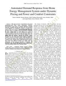
transportation grid (highway, city roads, etc). Lastly, vehicles, as communication nodes, have abundant life and computing power as compared to sensor networks. Our research focus is on designing vehicular mesh (VMesh) networks as reliable data transit networks. A mesh network is an ad-hoc network with no centralized authority or infrastructure. Nodes can move, be added or deleted, and the network will realign itself. The benefits of a mesh network are that it has the abilities of self-forming, self-healing, and self-balancing. As shown in Figure 1, one of the applications of using VMesh as a transit network is to establish connections between disjoint sensor networks.
I. INTRODUCTION Sensor Network A
US FCC has allocated a block of spectrum from 5.85 to 5.925 GHz band for inter-vehicle and roadside-to-vehicle communications that can support a wide range of applications. Such ad-hoc communication modes complement cellular communications by providing very high data transfer rates in circumstances where minimizing latency in the communication link and isolating relatively small communication zones are important. Previous work on vehicular communication has mainly focused on supporting two broad categories of applications: a) vehicular safety, such as exchanging safety relevant information or remote diagnostics using data from sensors built into vehicles and b) mobile internet access. However, there is a large untapped potential of using such vehicular networks as powerful and distributed computing platforms or as transit networks. Vehicular networks have very different properties and design challenges compared to their counterparts such as laptops in nomad computing or sensor networks. First, vehicles travel at a much higher speed, making it challenging to sustain communications between stationary sites and moving vehicles, as well as handing-off the communication link from one site to the other as the vehicles pass between them. Second, despite the common assumption of random mobility patterns in many simulation studies on ad hoc networks, the vehicular traffic has a more well defined structure that depends on the
Sensor Network C
Sensor Network B
Fig. 1.
Using VMesh to connect disjoint sensor networks
One of our expectations for VMesh is to enable demand response (DR) [1] for automatic utility usage retrievals and price dispatching. DR is a project initiated by California Energy Commission (CEC). The main spirit of the project is to allow utility companies to adjust utility prices based on real-time feedback from end users. With the advancement in consumer technologies, we assume that buildings are equipped with wireless sensors/transceivers that are capable of monitoring gas, water, and electricity usage, transmitting measured data, and receiving and processing price information. VMesh can be used to interconnect these sensors and the backbone wide-
area network (WAN) infrastructure, e.g., Internet backbone, wireless cellular infrastructure, DSL or Cable. We will discuss some key properties that we expect VMesh to have to support DR in the next section. In Section III, we will describe VMesh architecture and some design considerations. We will summarize and introduce our proposed routing algorithm in Section IV. Lastly, we will show some preliminary results in Section V. II. VMESH DESIGN RATIONALE FOR DEMAND RESPONSE We envision that VMesh leverages a variety of vehicles, ranging from public transit (e.g., buses, light rail) to vendor trucks (e.g., FedEx, UPS) and police cars, to form a dynamic group of mobile routers. These vehicles, or MRs, are responsible for disseminating price information to and retrieving information from different households to support dynamic tariffs and demand-response. In this case, VMesh is designed to meet the following goals: •
Low Deployment and Maintenance Cost: Since the routers in this case are ”mobile”, one can drive these mobile routers into a station (e.g., main bus station or police headquarters) for repairs or software/hardware upgrades, instead of having to send a repair team out to various locations to fix the problems if they were stationary. Moreover, the number of mobile routers required can be minimized, e.g., using buses traveling on different routes is sufficient to cover the entire city. Hence, both the installation and maintenance costs are greatly reduced.
•
Adaptive Fidelity: By using a combination of vehicles as mobile routers, VMesh provides a wide spectrum of flexibility in terms of the frequency of message retrieving and the granularity of demand response control loops. For example, while buses run every 0.5 - 1 hour, they do not stop at every single household. On the other hand, garbage trucks may stop at every household but they only come by once a week.
•
Scalability: VMesh can support incremental deployment easily as the number of sensor nodes grows. In fact, VMesh benefits from the economy of scales, i.e., the cost of introducing a new mobile router goes down as the number of sensor nodes it is capable of serving increases.
•
Broadcast and Multicast Capabilities: Broadcast and multicast capabilities are inherent in the wireless communications used between the mobile routers and sensor nodes, between the mobile routers and aggregation points to the VMesh network backbone, and between mobile routers and other vehicles equipped with wireless transceivers.
•
High Level of Redundancy: VMesh has a high level of built-in redundancy by leveraging different vehicles that overlap in spatial coverage and temporal samplings. For example, there may be different routes for public transit through the city, but these routes often overlap in the main
streets. In addition, garbage and postal trucks will visit the households on the same street at different times of the day. Therefore, the same end-user can be connected by two or three different types of vehicles. There are multiple available paths to ensure the delivery of the DR messages. •
Failure Resiliency via Deflection Routing: VMesh ensures the survivability of the DR messages by deploying the deflection routing technique. The key premise lies in the ability of VMesh to deflect messages until a valid path is found to the destination instead of dropping them when the original path fails due to faulty mobile routers, broken communication links, or vehicular accidents.
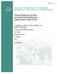
DR is one type of applications the VMesh network is capable of supporting. In addition to supporting demand response, VMesh also enables the deployment of other large-scale societal applications such as amber alert (e.g., broadcasting information of a kidnapper’s vehicle and detecting this moving target), vehicular traffic control, and temperature/air-pollution monitoring. In the next section, we will first introduce a generic VMesh network architecture and then describe the method to support DR with this generic architecture. III. VMESH ARCHITECTURE Traditional sensor networks are developed in a way that sensors are installed close enough to provide direct communications. If the deployment area is vast, one or more data collection base stations and clustering techniques are required to reduce the overhead of data transmissions. When the covering area is large, base stations may use other sensors, which have limited power, as gateways to relay messages or increase transmission power to increase transmission range if possible. However, increasing the power also increases the interference to other nodes in the network and using other sensors as gateways drains out the energy of some specific nodes more quickly. Both methods have their own drawbacks and may decrease the stability of the network. If the latency requirement of data in a network is not critical, we can alleviate this problem by using the VMesh network, which has one or more mobile routers as an essential component. As these mobile routers move by, they can collect and disperse information to static base stations. An example of using mobile routers to collect data is represented in [2]. Vehicular mesh networks are ad hoc networks formed by vehicles enabled with wireless networking. As the vehicles move, the connectivity between the vehicles and other static network nodes changes. The network is dynamic and as a result, nodes may be disconnected from the network at times. To address this, nodes will store the data during the period they are disconnected from the network. An example vehicular mesh network is shown in Figure 2. The figure shows two bus routes (Route 136 and Route 108) and some key components of VMesh. The key components of the architecture are as follows:
Inbound/ Outbound Message Flow
AP
678
STU
&HQWUDO�*DWHZD\�WR� 90HVK�:$1��&*
&HQWUDO�2IILFH
ZLUHOHVV '5�%DFNERQH�:$1 Fig. 2.
An illustration of proposed VMesh architecture
1) Sensing and Transceiving Units (STUs) are wireless enabled sensors that will transmit collected data to the central office (inbound message). They also receive new configurations such as new pricing information generated by the central office (outbound message). These are shown as solid circles in Figure 2. If STUs cannot directly connect to the VMesh backbone network, they can form a network themselves to route inbound and outbound messages. 2) Aggregation Points (APs) are nodes that act as gateways to the VMesh. They can aggregate inbound messages, relay the messages to the VMesh, accept outbound messages, and route these outbound messages to one or more STUs. These gateways could be special nodes deployed at appropriate locations or specific STUs that are enabled with the gateway functionality. 3) Mobile Routers (MRs) are wireless enabled mobile objects that have the ability to store and forward data. For example, buses, along with other various types of vehicles equipped with storage and wireless networking, form ad hoc networks with other mobile routers and connect to the static gateways. 4) Central Gateways to VMesh (CGs) are gateways which connect different VMesh networks. These are located at specific locations on the paths of mobile routers, such as at the main terminal stop of buses. The characteristics of VMesh depend on the mobility pattern of the participating mobile routers as well as neighboring vehicles. The choice of vehicles that are suitable for VMesh heavily depends on their attributes which include:
1) Coverage: How many STUs are directly accessed? We refer to the coverage as being fine-grain if the MRs can directly access individual or small groups of STUs directly. 2) Schedule and Periodicity: Is there a fixed schedule in the mobility pattern of MRs and if so, what is the period? 3) Redundancy: Are STUs or APs covered by multiple MRs? Are there multiple paths from the individual STUs to the APs? 4) Cost: What is the cost of deployment and maintenance in terms of the number of STUs, MRs, and APs? For example, buses provide coverage to almost every major street in a dense major city such as San Francisco and their schedules coincide with peak electricity usage (e.g., buses run more frequently during work hours when energy consumption is high than at night). The mobility pattern of the vehicles depends on the type of vehicles, which include personal automobiles, public transport buses and light rails, postal vans, garbage trucks, various types of vendor trucks and vans such as UPS and FedEx, law enforcement vehicles such as police cars, and other monitoring vehicles such as those that monitor parking violations. Various types of vehicular mesh networks can be characterized along these parameters depending on the targeted geographic area. An example of such characterization for a suburban area is shown in Table I. For the case of demand response, DR is enabled in the following manner. Periodically, the sensors transmit collected data that are routed to one or more aggregation points through a local ad-hoc network. When the mobile router travels by
Coverage Schedule Period Redundancy Cost
cars Fine (1-10 m) Regular 24 hrs Low High
Buses Coarse (10-1000 m) Regular 15 mins Medium Low
Postal Vans Fine (1-10 m) Regular 12/24 hrs Low Low
Garbage Trucks Fine (1-10 m) Regular 7 days Low Low
Vendor Trucks Coarse (10-1000 m) Random Few Hours Medium Low
Police Cars Coarse (10-1000 m) Random None High Low
TABLE I A QUALITATIVE CHARACTERIZATIONS OF VARIOUS TYPES OF MR S FOR A VM ESH IN A SUBURBAN AREA
these aggregation points, it downloads the collected data and uploads new configurations which are distributed to the sensor nodes using local ad-hoc networks as well. The collected data can be opportunistically routed by the vehicular mesh network to the central gateways. In the worst case, the central gateway may be located at the terminal point of the route of the mobile router. We will discuss about routing issues based on this architecture in the next section. IV. ROUTING IN VMESH Many unicast and multicast routing algorithms have been proposed for MANET. However, not all of them are fit well in our VMesh network. For example, Destination-Sequenced Distance-Vector Routing (DSDV) [3] needs network-wide update messages. If every household has at least one sensor, like the case in demand response, the density of sensors would be extremely high. Hence, network wide route update messages will drain out the energy of sensors quickly. Adhoc On-Demand Distance Vector Routing (AODV) [4] uses bi-directional links but one field study [5] has shown that this may not always be true in real life. The main disadvantage of Dynamic Source Routing (DSR) [6] is the long routing table. Because nodes in a DSR network need to store all the routing sequences toward intended destinations, the routing table will be prohibitedly long if the network is dense. For detail routing algorithm reviews, please refer to [7] [8] [9] [10]. In the following subsections, we will discuss routing issues from STUs to APs, APs to MRs, and MRs to MRs separately. A. Between STUs and APs The main challenges of routing from sensor to aggregation point are fault tolerance and energy awareness. Therefore, we choose Greedy Perimeter Stateless Routing (GPSR) [11] as our backbone algorithm to send data from sensors to APs. In GPSR, we need to establish a planar network, such as a Gabriel Graph (GG) or Related Neighborhood Graph (RNG) to eliminate intersecting edges in the network. After that, two routing algorithms, greedy forwarding and perimeter routing, are used to deliver packets. GPSR uses the most forwards within radius (MFR) greedy algorithm as the general packet forwarding algorithm to minimize hop counts. MFR always tries to find a node within transmission range which can provide the smallest remaining distance toward destination. If MFR greedy algorithm causes local optimization, the perimeter routing takes over and routes the packet around the
perimeter of a face according to the right hand rule. Every node that receives a packet through perimeter forwarding calculates the distance to the destination. If the distance is smaller than that from the node that initiates perimeter routing to the destination, it will switch back from perimeter routing to MFR greedy forwarding . In a case like DR, information will be sent out frequently by the APs. During the new information dispatching phase, new information are broadcasted over the whole network. In [12] and [13], low overhead flooding algorithms have been presented. Instead of establishing static multicast trees, we can use the algorithm in [13] to dispatch messages. A node in [13] sets up a random backup timer based on the forwarding progress when a new broadcast message is received for the first time. If the node receives the same message from all directions (NE, NW, SE, SW) before the timer has expired, it cancels the timer. Otherwise, the node resends the message. In our VMesh network, we may have hundreds of STUs trying to send data to an AP at the same time. This situation puts heavy loading on the MAC layer. Therefore, we will apply clustering techniques to decrease MAC layer loading and retransmissions. Conventionally, when a node wants to transmit information back to the aggregation points, it sends packets to the cluster head first. The cluster head will then forward the packets to the next cluster head through a onehop broadcast or use other sensors as gateways and perform multihop relaies. Broadcasting and clustering are two similar techniques but work in the opposite ways. Brodcasting best suits for one-to-many scenarios while clustering is many-toone. The optimal solution for both broadcasting and clustering is to use the minimum number of nodes to cover the whole network space. Nodes in the VMesh network can record the nodes that they received messages from and then use them as the cluster heads for return paths. In the original GPSR, a node tries to select another node that can provide the most forwarding progress as the next hop. This characteristic will quickly drain out the energy of certain nodes that are located on critical paths. In our proposed routing method, next hops are the cluster heads that are chosen randomly according to the forwarding progresses during each data dispatching phase. Since the backup timers are chosen randomly, the nodes that rebroadcast messages are different from time to time. This indicates that the next hops which are actually cluster heads are distributed in a set of nodes instead of being fixed. Because the cluster heads are chosen dynamically during each new message dispatching phase, this
method is also more resilient to network disconnection caused by a single node failure. Suppose now a node who claims itself as a cluster head dies after rebroadcasting a message. Our routing scheme fixes this issue by two methods. First, the modified GPSR in our case choose cluster heads as predefined next hops. Nodes can pick another node in the one hop neighbor list as the new next hop or switch to perimeter mode if the failures of cluster heads cause local optimizations. Second, nodes running out of energy are excluded from the candidate lists automatically so new cluster heads are chosen in the next message dispatching phase. B. Between MRs and APs: In the VMesh architecture, aggregation points are static transceivers by the roadside so mobile routers can get very close to the aggregation point. Therefore, simple one hop broadcasting is sufficient for message transferring. C. Between MRs: One very important usage of the addressed VMesh network is to deliver time sensitive information such as dispatching new utility prices to end users. In this case, a utility company can provide more accurate pricing information if the company gets more feedback from users. Therefore, we plan to setup a deflection routing environment to increase the robustness of the network and to decrease the message delivery latency to allow more information being sent back to the central gateway. Deflection routing has been proposed to reroute packets during a node or link failure in the IP networks to reduce the transient link overloads and packet loss rates [14]. We propose to apply similar techniques to our VMesh network by deflecting messages toward the destination from one mobile router to nearby vehicles or backup mobile routers when the primary communication path fails, or when the primary mobile router is trapped in a traffic congestion that may cause intolerable end-to-end latency. This ensures that the messages are routed around trouble instead of being dropped. The fundamental routing protocol between mobile routers is also location-based GPSR. Therefore, location servers may be required. If we limit deflection routing to single hop transmission, we can finish deflection routing without the presence of location servers. On the other hand, if there are location service servers from which a mobile router can retrieve the location of other vehicles, the mobile router can deflect the message to other vehicles outside the transmission range through multihop transmissions. V. PRELIMINARY RESULTS We have implemented the algorithm discussed in [2] in C under the Unix environment. We use a 40 x 40 grid network and random walk mobility model as our baseline settings during simulation. The number of aggregation points is set to 1 and the densities of sensor nodes and mobile routers are either 0.01 or 0.05. There are two different communication
methods between mobile routers during simulations. In the first configuration (NOTALK), mobile routers can send data to the aggregation point only, while disallowing MR to MR communications. In the second configuration (BROADCAST), mobile routers can broadcast their data to all other mobile routers within the transmission range. The performance metrics we consider are data success rate (DSR) and average delay latency. If NC is the number of non-duplicated data packets collected by the aggregation point during time T and NG is the number of data packets generated by all the sensors C during time T, the way to calculate DSR is N N G . On the other hand, average latency is the average time difference between the time when a packet is generated and the time when it is collected. Since we consider four different node densities, 2 communication methods, and 10 different transmission ranges, there are 80 different scenarios in total. From Figure 3, we can see that the DSRs increase linearly with the increasing of the transmission range of mobile routers when NOTALK method is used. When BROADCAST method is used, as shown in Figure 4, DSRs increase more rapidly and hit a saturation value when the transmission range is 6. We can also notice that the density of mobile routers is the dominant factor that affects the performance of the system. The system performs better when the density of mobile routers is high. In Figure 5, we compare latency values derived from BROADCAST and NOTALK when sensor density is 0.05. Results show that latencies in NOTALK and BROADCAST decrease by following a similar slope except when the mobile router density and sensor density are both 0.05. In this case, latencies drop much faster and also saturate when the transmission range is 6. Finally, we look at how the differences between BROADCAST and NOTALK vary with the changes of the transmission range. BROADCAST results in Figure 6 are normalized to NOTALK when the sensor and mobile router densities are both 0.05. The results indicate that when the transmission range is small, the difference between BROADCAST and NOTALK is relatively small. As the transmission range increases, the gaps first increase then decrease. This is due to the fact that BROADCAST grows faster and reaches a saturation value earlier than NOTALK. VI. CONCLUSION AND FUTURE WORK While there are many advantages of the network solution described above, for sake of brevity, we enumerate only the important ones and use the case of utility pricing dissemination and usage retrieval as an example. In this case, the network is scalable and the performance of the Vmesh network is also dependent on the design of bus routes. The vehicular mesh network can minimize the number of user-side and utility-side gateways thereby minimizing the deployment cost. Since the maintenance can be done at the bus depot, the cost will be low. Hence, the cost of deployment and maintenance is low. The next step of this project is to implement our proposed routing algorithm and simulate it in ns-2. Future work will focus on comparing the performance of the proposed algorithm to the original GPSR algorithm and static multicast tree to see the
0.8
350
300
0.6 250
0.5 Latency
NOTALK Data Success Rate (DSR)
0.7
200
0.4 150
0.3
100
0.2
0.1
Mobile Router / Sensor Density = 0.01/0.01 Mobile Router / Sensor Density = 0.01/0.05 Mobile Router / Sensor Density = 0.05/0.01 Mobile Router / Sensor Density = 0.05/0.05
NOTALK: Mobile Router / Sensor Density = 0.05/0.01 NOTALK: Mobile Router / Sensor Density = 0.05/0.05 BROADCAST: Mobile Router / Sensor Density = 0.05/0.01 BROADCAST: Mobile Router / Sensor Density = 0.05/0.05 50
1
2
Fig. 3.
3
4
5 6 Transmission Range
7
8
9
10
1
2
Fig. 5.
NOTALK DSR in Various Transmission Range
3
4
5 6 Transmission Range
7
8
9
10
BROADCAST Latency in Various Transmission Range
2.5
0.9
DSR Ratio Latency Ratio
BROADCAST / NOTALK DSR and Latency Ratio
BROADCAST Data Success Rate (DSR)
0.8
0.7
0.6
0.5
0.4
0.3
1.5
1
0.5
Mobile Router / Sensor Density = 0.01/0.01 Mobile Router / Sensor Density = 0.01/0.05 Mobile Router / Sensor Density = 0.05/0.01 Mobile Router / Sensor Density = 0.05/0.05
0.2
0.1
2
1
Fig. 4.
2
3
4
5 6 Transmission Range
7
8
9
10
BROADCAST DSR in Various Transmission Range
performance difference. In addition, we will use a microscopic traffic simulator to generate realistic vehicle trace files and then re-generate the latency and data delivery success rates. R EFERENCES [1] California Energy Commission (CEC). [Online]. Available: http://www.energy.ca.gov/demandresponse/ [2] Rahul C. Shah, Sumit Roy, Sushant Jain, and Waylon Brunette, “Data MULEs: Modeling a Three-tier Architecture for Sparse Sensor Networks,” Technical Report, Intel Research Lab at Seattle, Tech. Rep. IRS-TR-03-001, Jan. 2003. [3] Charles Perkins and Pravin Bhagwat, “Highly Dynamic DestinationSequenced Distance-Vector Routing (DSDV) for Mobile Computers,” in ACM SIGCOMM’94 Conference on Communications Architectures, Protocols and Applications, 1994, pp. 234–244. [4] Charles E. Perkins and Elizabeth M. Royer, “Ad-hoc On-Demand Distance Vector Routing,” in IEEE WMCSA’99, New Orleans, LA, Feb. 1999, pp. 90–100. [5] Benjamin A. Chambers, “The Grid Roofnet: a Rooftop Ad Hoc Wireless Network,” Master’s thesis, MIT, 2002. [6] David B Johnson and David A. Maltz, “Dynamic Source Routing in Ad Hoc Wireless Networks,” in Mobile Computing, Imielinski and Korth, Eds. Kluwer Academic Publishers, 1996, vol. 353. [7] Elizabeth M. Royer and Chai-Keong Toh, “A Review of Current Routing Protocols for Ad-Hoc Mobile Wireless Networks,” Apr. 1999.
0
1
2
3
4
5 6 7 Transmission Range
8
9
10
Fig. 6. Normalized DSR and Latency when AP/Sensor Density = 0.05/0.05
[8] Martin Mauve, J¨org Widmer, and Hannes Hartenstein, “A Survey on Position-Based Routing in Mobile Ad-Hoc Networks,” IEEE Network 15 (6), pp. 30–39, Nov. 2001. [9] Carlos de Morais Cordeiro, Hrishikesh Gossain, and Dharma Agrawal, “Multicast over Wireless Mobile Ad Hoc Networks: Present and Future Directions,” IEEE Network, Jan. 2003. [10] Martin Mauve, Holger F¨ußler, J¨org Widmer, and Thomas Lang, “Position-Based Multicast Routing for Mobile Ad-Hoc Networks,” Technical Report, Department of Computer Science, University of Mannheim, Tech. Rep. TR-03-004, 2003. [11] Brad Karp and HT Kung, “GPSR: Greedy Perimeter Stateless Routing for Wireless Networks,” in Proc. of 6th ACM/IEEE MobiCom, Aug. 2000, pp. 243–254. [12] Vamsi S. Paruchuri, Arjan Durresi, Durga S. Dash, and Raj Jain, “Optimal Flooding Protocol for Routing in Ad-hoc Networks,” Submitted to WCNC 2003. [13] Jesus Arango, Mikael Degermark, Alon Efrat, and Stephen Pink, “An Efficient Flooding Algorithm for Mobile Ad-hoc Networks,” in WiOpt 2004. [14] Sundar Iyer, Supratik Bhattacharyya, Nina Taft, and Christophe Diot, “An Approach to Alleviate Link Overload as Observed on an IP Backbone,” in Proc. of IEEE Infocom, Apr. 2003.