Physical Communication 9 (2013) 1–15
Contents lists available at SciVerse ScienceDirect
Physical Communication journal homepage: www.elsevier.com/locate/phycom
Full length article
Enabling next generation small cells through femtorelays Ian F. Akyildiz ∗ , Elias Chavarria-Reyes, David M. Gutierrez-Estevez, Ravikumar Balakrishnan, John R. Krier Broadband Wireless Networking Laboratory, School of Electrical and Computer Engineering, Georgia Institute of Technology, Atlanta, GA 30332, United States
article
info
Article history: Received 26 February 2013 Received in revised form 1 April 2013 Accepted 4 April 2013 Available online 23 April 2013 Keywords: Femtocell Femtorelay Relay Small cells Heterogeneous networks Interference Backhaul congestion
abstract Today’s society is driven by ever-growing information needs, which cause increased demand for ubiquitous and very high speed wireless communications. In search for the urgent need of improved coverage and capacity, cellular networks are currently undergoing a major transformation from an architecture comprised of thoroughly planned macrocell base stations (MBSs) to a much more heterogeneous architecture where the macrocell network is underlaid by one or several tiers of unevenly deployed small cells. However, this new set of technologies is not exempt of several challenges. Backhaul is still an unresolved issue, i.e. which is the best technology for the small cell to reach the core network. In the case of uncoordinated co-channel deployments where the macrocell and small cell tier share the spectrum (e.g. femtocells or metrocells), the interference is also a major problem. In this paper, a new concept and architecture called femtorelays is introduced as a novel solution for next generation small cell problems. A femtorelay is a small cell access point that enables improved cellular coverage within indoor environments while increasing the overall system capacity through spatial frequency reuse. Working as an open-access small cell, it provides dual-backhaul connectivity to the core network for registered and unregistered users. One of the backhaul connections is the internet-based, and the second one is the relay-based operating on the spectrum owned by the wireless carrier. The radio interference between the macrocell and the small cell is overcome by servicing the macrocell interfering users at the femtorelay. Unlike the traffic from subscribers, this traffic will be forwarded to the network through the relay-based backhaul. The internal architecture, the approach employed to make the technology fit in existing networks, and future evolution of the basic femtorelays for larger scenarios are also presented. Finally, performance results show the potential of this technology to outperform other existing solutions. © 2013 Elsevier B.V. All rights reserved.
1. Introduction An unprecedented revolution is taking place in the field of wireless communications, driven by the ubiquitous demands from mobile users for ever-increasing wireless data and services. The proliferation of wireless mobile devices
∗
Corresponding author. Tel.: +1 404 894 5141; fax: +1 404 894 7883. E-mail addresses:
[email protected] (I.F. Akyildiz),
[email protected] (E. Chavarria-Reyes),
[email protected] (D.M. Gutierrez-Estevez),
[email protected] (R. Balakrishnan),
[email protected] (J.R. Krier). 1874-4907/$ – see front matter © 2013 Elsevier B.V. All rights reserved. http://dx.doi.org/10.1016/j.phycom.2013.04.001
including smartphones and tablets has tremendously increased the need for high-speed broadband services. In their last Visual Networking Index (VNI) report, Cisco forecasted an 18-fold traffic increase by 2016, reaching the quantity of 10.8 exabytes of data per month [1]. In addition, studies also show that more than 50% of voice traffic and 70% of cellular data traffic originate from indoor and enterprise environments [2]. Cellular networks are thus faced with the challenges of providing enormous system capacity and achieving superior cellular coverage. As a result of this context, the design and development of 4G cellular systems and beyond such as 3GPP’s Long Term Evolution (LTE) Advanced are being shaped by this
2
I.F. Akyildiz et al. / Physical Communication 9 (2013) 1–15
challenge. Since techniques from the past such as increasing the amount of spectrum or the number of macrocell base stations (MBSs) have become prohibitively expensive, these new systems are all in need of incorporating fundamental advances in their core technologies to enable the delivery of extremely high data rates to the end user. A wide spectrum of new techniques comprising, among others, carrier aggregation, advanced MIMO, cooperative communication, and self-organizing networks are currently being both investigated and standardized [3]. However, historical data regarding capacity improvements in wireless networks show that the largest gains ever obtained come mainly from the use of smaller cells. These can provide an increase in network capacity of more than three orders of magnitude [2,4]. For this reason, the paradigm of Heterogeneous Cellular Networks (HetNet), comprised of a macrocell network underlaid by one or several tiers of small cells, has become a key element in the envisioned future cellular system of every wireless carrier across the world [4]. A tremendous activity on small cells has been conducted in recent years by standardization bodies including 3GPP, 3GPP2 and the WiMAX forum [5,6]. Similarly, world-wide academic research and industry efforts, which include leading service providers and equipment manufacturers, have embraced small cell technology as a key element for future wireless cellular systems. Small cell systems of reduced coverage are utilized by wireless carriers as one of the primary solutions to improve signal quality, cellular coverage and capacity at places like hotspots, macrocell edges, and indoor environments. The deployment of these systems can be carefully planned by the operator or rather random as users may deploy them by themselves. The size of the coverage areas may differ as well, ranging from 10–15 m up to 1–2 km. Hence, a varied range of small cell solutions for 3G and 4G cellular systems have already been adopted and deployed causing the whole small cell market value to surpass $200 million in 2012 [7]. More than 5 million small cells have already been deployed and forecasts show that the deployments of small cells will grow exponentially and reach over 90 million units by 2016 [8]. Nevertheless, most small cell solutions available today, and particularly femtocells, often suffer performance degradation due to severe interference with other cells and backhaul bottleneck issues, among others [2,9–12]. Current deployments of small cell solutions face several major challenges that may inhibit their large-scale adoption: (i) cross-tier interference, (ii) co-tier interference, (iii) backhaul bottleneck, (iv) service degradation due to user mobility, and (v) privacy issues. First, small cell users and nearby macrocell users can significantly interfere with each other when they operate in the same licensed band. This cross-tier interference is the major issue in closed access deployments [9]. Second, small cells deployed in proximity can also interfere with each other. This co-tier interference can be a major issue in enterprise scenarios where many femtocells are densely deployed in a building. Third, the internet-based backhaul may suffer congestion resulting in a backhaul bottleneck [10] that fails to provide consistent and required quality of service (QoS) to
satisfy user expectations. Fourth, service may be degraded or even interrupted when the mobile users hand over from small cells to macrocells, from macrocells to small cells, or among different small cells. Finally, privacy issue becomes a major concern when privately-owned small cells such as femtocells are open to macrocell users and their traffic is routed through the femtocell owner’s private backhaul [11]. To address the aforementioned small cell challenges, we introduce the femtorelay technology, a novel, costeffective small cell solution offering better performance than existing solutions. It aims to offer improved cellular coverage, enhanced system capacity, and guaranteed QoS and affords their mobile users a seamless wireless broadband experience. At the heart of our idea is the patented femtorelay system architecture [13]. This novel architecture lays the foundations of our innovations in relaying technology, cross-tier and self-interference cancellation, dynamic backhaul switching, co-tier coexistence optimization through our multi-femtorelay centralized coordination technique, and enhanced user mobility. Moreover, femtorelay does not require careful radio frequency planning or dedicated backhaul to the operator’s core network, hence reducing capital expenditure (CAPEX) and operating expense (OPEX) not only when compared to the expensive deployment of traditional base stations, but also to other small cell solutions. The overall capacity of the system will be enhanced, allowing the accommodation of more datademanding customers in the network. Specifically, the femtorelay small cell technology provides the following benefits: • Improvement of cell coverage. A novel architecture is proposed with the capability of relaying the macrocell traffic between MBSs and macrocell users (MUs) at the cell edge with the target of increasing the coverage of macrocells. Moreover, the indoor coverage is simultaneously improved by the deployment of femtorelay for small cell users. • Enhancement of system capacity. The system capacity is mainly enhanced by minimization and cancellation of cross-tier, co-tier, and self-interference. First, the relaying technology effectively minimizes cross-tier interference between macrocell users and small cell users. Second, coordination through a centralized management entity in the multi-femtorelay minimizes co-tier interference in large indoor environments. Third, a new self-interference cancellation technique based on both active and passive approaches is developed to cancel the interference from the transmitted signal in the receiving path to enable full-duplex transmission on the same frequency bands, which further enhances system capacity. • Guarantee of QoS. The QoS is guaranteed by two innovations: (i) dynamic backhaul switching and (ii) seamless mobility. First, since industry trials have shown difficulties for femtocell data transfer over a single IP backhaul, a key innovation of this technology is the enabling of a dual backhaul via relaying for QoS enhancement at a single small cell access point. Second, seamless handling of users moving in and out of the small cell coverage area is achieved through novel mobility management procedures. Also supported is the feature of backhaul switching, which performs load balancing to guarantee users’ QoS.
I.F. Akyildiz et al. / Physical Communication 9 (2013) 1–15
3
• Transparent support and scalability. A gateway component for the core network to facilitate rapid large-scale adoption is introduced. This gateway, providing standard interfaces to the network elements, helps to significantly minimize the impact of our technology on the network. The gateway also acts as an aggregator of traffic from several of our small cell access points toward the network. The remainder of this paper is organized as follows. Section 2 gives an overview of technologies related to the femtorelay concept, namely femtocells, relays and other combinations of both. In Section 3 the femtorelay concept is described along with its main features. Section 4 describes the network architecture, i.e. how this technology is compliant with the existing network infrastructure. Performance evaluation results are shown in Section 5, and Section 6 presents the evolution of this technology for larger coverage scenarios. Finally, conclusions are drawn in Section 7. 2. Related technologies The limitations behind current femtocell and relay technologies motivated the development of the femtorelay concept. Other solutions have attempted to exploit synergies between relays and femtocells at different levels. We propose a novel approach with great potential to provide significant advantages compared to previous ones. Before describing in detail our proposal, we introduce femtocells, relays, and existing approaches of merging them. 2.1. Femtocells Femtocells have appeared in recent years as an alternative technology for service providers to expand the coverage and capacity of their networks in indoor environments [14]. In a typical network a user is served by a base station (NodeB or eNodeB in 3GPP terms) [15,16] whose deployment is planned and performed by the service provider. The coverage provided by the base station is referred to as the ‘‘cell’’. According to the size of the cell, different names are further used to differentiate them: macrocell, microcell and picocell (in decreasing order of size). Currently, femtocells are the smallest member of this set. The femtocell service is provided by a device called femtocell access point, or FAP (Home NodeB, or Home eNodeB in 3GPP terms) [5,16]. The FAP is a small size, low cost, and low power device acquired and installed by the end user within the indoor environment. Its purpose is to provide an enhanced indoor coverage to a small number of users (5–10 users).1 This is achieved due to the relatively small distance between the FAP and the end user compared to the distance to the base station. As shown in Fig. 1, the connection between the FAP and the core network (CN) of the service provider is done through an internet protocol (IP) backhaul such as an internet connection. On the CN side, to ease the load on the existing CN elements, 1 This number keeps increasing as technology evolves and new scenarios for femtocells are proposed.
Internet
Service Provider
FAP User User
Fig. 1. Femtocell network architecture.
a gateway may be introduced in order to support the signaling and data connections received and transmitted from the FAPs. This scheme introduces new challenges and requirements for femtocell deployments. The fact that the end user is the one that decides when and where the FAP is installed leads to the first set of requirements. First, the FAP should allow a plug-n-play installation in order to minimize any intervention from the end user. Second, the service provider can no longer preplan the precise deployment of these devices. Therefore, femtocells should dynamically self-adjust to the environment in which they are deployed in order to maintain and improve the network stability and performance. In addition to the end users’ freedom of FAP deployment, the utilization of the end user’s internet connection as the link between the FAP and the CN provides the second set of requirements and constraints. First, the internet connection used by the FAP is also shared by all other home devices that require internet access, such as laptops, tablets, home entertainment systems, etc. Therefore, the quality of the service provided by the femtocell may be hindered by the internet connection usage due to other devices within the home network. From the service provider point of view, this is an important issue since (in the general case) it has no control over the internet connection of the end user, as to prioritize the femtocell traffic. In addition, any degradation of the performance provided by the femtocell is perceived by the end user as a fault of the femtocell irrespective of whether the degradation is due to the internet connection or the FAP. This leads to lower customer satisfaction and higher risk of churn. Second, the end user may want to limit the access to his femtocell to a specific set of devices. The reason for this behavior is the fact that all femtocell traffic is traversing the local network and using the private internet connection. This has led to the introduction of different ‘‘access modes’’ for femtocells: open (anyone can connect), hybrid (anyone can connect, but receiving different priorities), and closed (a specific set of authorized devices can connect). While typical femtocell deployments are characterized by having to deal with interference issues with the rest of the cells in the network, closed femtocells aggravate these interference issues. In a typical femtocell scenario, the uplink transmission of the femtocell user (FU) will cause interference to the base station, while the downlink transmission of the base station will cause interference to the FU. In a closed femtocell scenario, non-authorized macrocell users (MU) can get as close as they desire to the FAP and still not be able
4
I.F. Akyildiz et al. / Physical Communication 9 (2013) 1–15
to access the femtocell service. This causes the interference problems to increase even more. The non-authorized user may receive strong downlink interference from the FAP, while at the same time the FAP may receive strong uplink interference from the non-authorized user. In open and hybrid femtocells the non-authorized user could be switched so as to be served by the FAP. However, in a closed femtocell the non-authorized user is not allowed to connect to the FAP. These scenarios have been studied in detail by 3GPP [17] and academia [18–24], and several techniques to mitigate these interference issues have been proposed. In [18], the use of a different carrier for HSPA FAPs is proposed to mitigate downlink interference, as well as the dynamic adjustment of their transmission power. However, reducing the transmission power has the side effect of reducing the coverage and capacity of the FAPs. To mitigate uplink interference, limiting the transmission power of the FU is proposed in [19]. For OFDMA FAPs, several techniques are proposed in [21] for orthogonal and co-channel FAP deployments. In general, the techniques can be classified as static or dynamic, centralized or distributed, and cooperative or noncooperative. Within this framework, the concept of self-organizing networks has gained significant importance as a tool to tackle the interference problem [22,24], due to the dynamic nature of femtocell deployments. However, most of these techniques would require extensive proprietary modifications to the current femtocell standards in order to be effective. 2.2. Relays Relays and repeaters have been considered as a cost effective solution under the heterogeneous paradigm to improve radio coverage as well as to accommodate the ever-growing cellular data traffic [25]. Analog repeaters are devices that simply amplify the received analog signals from base stations and forward them to the users. One of the fundamental limitations of this approach is that repeaters also amplify the noise accompanying the analog signal. Relays are an alternative and a more evolved technology compared to analog repeaters [26]. A relay node (RN) is a low-powered base station serving a smaller number of users and has a carrier-based wireless backhaul with the macrocell base station. It is generally capable of downconverting the received signal from the MBS to baseband, thereby being able to decode and process the signal before transmitting it to the users. In general, the amount of processing an RN performs can differ largely. Certain relay implementations just enable demodulation and remodulation of the baseband signal, whereas others can actually enable decoding and processing of data including error handling, fragmentation, packing, rescheduling and reencoding [26]. An RN typically communicates with the mobile users in a point-to-multipoint fashion. The MBS communicates to RN in a point-to-multipoint fashion just as it communicates with mobile stations. Thus when both MBS and RN communicate to different mobile users using the same resources concurrently, it results in increased frequency reuse. There are several use cases of relays in a typical cellular network. This is illustrated in the Fig. 2.
RN 2
User User RN 5 MBS Coverage Hole
RN 3
RN 1
User User RN 4
User
Fig. 2. Use cases of relays in cellular networks.
• Relays provide coverage extension beyond the cell edge. This is particularly resourceful in rural and sparsely populated areas to provide coverage beyond the coverage regions of macrocells. • Relays also help overcome shadow regions in densely populated areas or the coverage holes in tunnels, subways to provide seamless coverage for mobile users. • Relays, in certain cases, provide multipath diversity for users within the macrocell coverage area. The macrocell can decide to transmit to the user simultaneously using both the direct one-hop link as well as the two-hop link through a relay node based on the traffic parameters. Such a configuration helps to increase the link capacity, although it does not contribute significantly to an improved network coverage. • Lastly, multi-hop relays can also provide coverage extensions in hilly areas or other areas where it is difficult to provide infrastructure for a full-fledged base station.
2.2.1. Relaying schemes Several relay architectures have been proposed for cellular systems [27–30], the key candidates being LTE-Advanced. Such relay architectures can be broadly classified into two categories: transparent relays and non-transparent relays depending on whether the RN can generate control messages or not [31–33]. These RNs can operate in two different modes—(1) simultaneous transmit and receive (STR) and (2) time-division transmit and receive (TTR). These relaying schemes are discussed briefly as follows. Non-transparent and transparent relays Non-transparent relays are capable of having unique cell IDs and generating their own downlink synchronization and control messages. This type of relay is able to schedule radio resources within its own cell. The distributed control also lets the mobile users to recognize the RN as an independent base station. Hence, the nontransparent RN can be considered as a small base station with full capabilities equipped with a wireless backhaul link to the network. The primary goals of non-transparent relays are to extend the signal coverage for remote users while also improving the total system capacity. Typically, this type of relay forwards Layer 3 packets between MBS
I.F. Akyildiz et al. / Physical Communication 9 (2013) 1–15
5
and mobile users. Non-transparent relays have been proposed for IMT-Advanced systems including IEEE 802.16m and LTE-Advanced. Transparent relays, on the other hand, are not capable of having their own cell IDs or able to broadcast downlink synchronization and control messages. In this case, the mobile users first synchronize with the MBS. The RN is able to hear the uplink transmission from nearby users and reports this to the MBS. The MBS after accepting the user into the network can make decisions to either send downlink transmission directly to the mobile user or through the RN. In the latter case, the MBS instructs the RN regarding the transmission frames. Users within the coverage area of the MBS can benefit due to the transmission from the RN in addition to the transmission on the direct path from the MBS. Hence, this type of relay primarily serves to enhance the link capacity for such users as well as the overall system capacity by means of providing multi-path diversity to mobile users. TTR and STR modes Relays can operate in two different modes—(1) timedivision transmit and receive (TTR) and (2) simultaneous transmit and receive (STR). The downlink frame configuration for both TTR and STR relays are shown in Fig. 3. Under the TTR mode, relays operate in a time divided fashion while receiving signals from MBS (as a user) and transmitting toward the MS (as a base station). In other words, transmission from MBS to RN takes place in time t0 , while the transmission from RN to users takes place in time t1 . The uplink transmission takes place in a similar fashion. This configuration allows relays to use the same radio frames used by the base station. Under the STR mode, relay concurrently receives DL transmission from the MBS while also transmitting on the DL to the users. If the BS ⇒ RN and RN ⇒ MS transmissions use the same resources, it results in self-interference, where the RN receives its own transmission as interference. This is generally avoided by modifying the frame structure to reserve dedicated resources for the BS ⇒ RN and RN ⇒ MS communication links. At the same time, this could also result in under-utilization of the radio resources. In order to overcome this dilemma, self-interference cancellation schemes must be used at the relay node to mitigate or eliminate the loop interference. 2.2.2. Relay benefits and limitations Relays offer several advantages. We have seen that relays address the problems of coverage and capacity. The alternative to the relay based solution is to deploy a larger number of micro or macro base stations. The disadvantage of the latter approach is that deploying new base stations will involve significant costs for initial deployment owing to the infrastructure required and subsequent maintenance of the dedicated wired/microwave point to point backhaul. On the other hand, since relays use wireless backhaul, the capital and operational costs are largely subsidized. Relays also offer deployment in an ad hoc fashion compared to fixed base station or other infrastructurebased small cell solutions since they do not require any wired backhaul to the core network; it also provides flexibility in the coverage area. Another major advantage of relays depending on the implementation is that they can range from very-low to low complexity in terms of the hardware involved resulting in low equipment costs.
Fig. 3. Downlink frame configuration for relay-enabled cellular network.
Relays have their inherent disadvantages, as well. Firstly, relays are susceptible to radio link failures at the backhaul, in which case, the mobile users can experience long delays and connection errors. Secondly, relays introduce additional interference into the network since they utilize the same spectrum as the BSs for communicating with the users. Thirdly, since relays need to decode the received signal and perform significant amount of processing before they can forward the signal to the destination node, relays offer increased network capacity at the expense of increased end-to-end latency. Certain configurations of relays require security key sharing with the serving base station, or even being able to generate and share keys with mobile users which can be a violation under the major network policies. Lastly, efficient relay operation calls for sophisticated radio resource management techniques. 2.3. Femtocell and relay combinations Although our femtorelay patented technology [13] described in this paper proposes a novel approach to exploit femtocells and relays synergic advantages, there are several other works in the literature that aim to obtain some gain out of the combination of femtocells and relays in cellular networks. In [34–36], femtocell users act as relays for macrocell users by relaying their data to the serving femtocell. The authors of [37] proposed a concept where signal decoding is not performed at the femtocell but at the MBS, and both FUs and MUs can access the open-access single-backhaul femtocell. Works targeted to improve backhaul performance by using both relay and femtocell internet-based backhauls have also been proposed. In [38] the femtocell backhaul is used to aid the macrocell backhaul when the latter is congested, and [39] proposes a rate-splitting approach where MUs can share their load between the direct macrocell link and an open-access femtocell using internet-based backhaul. Femtocells and relays can also coordinate to improve mobility or resource allocation performance as shown
6
I.F. Akyildiz et al. / Physical Communication 9 (2013) 1–15
Operator's Core Network
Internet
OPERATOR'S CORE NETWORK
MBS
Macrocell Base Station
FU
FrAP
Femtorelay
FrGW MU
Macrocell User
Femtocell Users
FU
Service/Packet Gateway
INTERNET Femtocell Gateway
Fig. 4. Femtorelay.
Fig. 5. Cellular network architecture with FrAP and FrGW.
in [40,41], respectively. All these concepts are very different from ours since no new small cell technology is proposed in any of them. Furthermore, they suffer from the need of re-architecting the network. Only the authors of [42] use a similar concept to ours for a femtocell and relay cooperation framework, but they assume LTE relay-enabled networks and hence their concept is not applicable to 3G networks. Further, femtocells need to be underutilized to be useful for MUs since no additional mechanism for optimizing femtocell resources is applied. Moreover, no self-interference mechanism is applied for an optimal usage of the available resources. 3. Femtorelay concept description A femtorelay is a small cell technology aimed at improving cellular coverage within indoor environments such as dwellings or enterprises while also increasing the overall system capacity through spatial frequency reuse. On the access network, a femtorelay access point (FrAP) serves as the access point providing cellular connectivity for the users within its coverage area. Fig. 4 depicts a FrAP operating in a home environment, which includes a wireless small cell access point with a dual backhaul, one internet-based and another one relay-based, the latter one operating on carrier’s licensed spectrum. As shown in Fig. 5, the internet-based backhaul connects to a Femtocell Gateway acting as an aggregator of several FrAPs traffic toward the CN [43,44]. The relay-based backhaul is enabled by a relay link between the FrAP and the MBS [26,45,46] that is supported from the core network side by means of a femtorelay gateway (FrGW). The FrGW, as part of the core network, enables transparent integration of FrAP into the network. Furthermore, an open-access approach is employed for servicing users, which means that the femtorelay users could be pre-registered with the FrAP as in the case of regular femtocell users (FUs) or just regular subscribers to the network operator, also referred to as macrocell users (MUs) [11,47,48]. Fig. 6 shows a simplified block diagram of the internal architecture of a FrAP. At a high level, it consists of (i) a femto processing module that is responsible for providing radio link to both FUs and MUs, (ii) a relaying module that provides a relay-based backhaul with the MBS used primarily for serving MU traffic, (iii) a smart
Fig. 6. Functional block diagram of FrAP.
open-access resource manager that is able to intelligently allocate resources to both FUs and MUs, (iv) a performance monitor that is able to monitor the backhaul performance of users, (v) a mobility management module that enables handover and backhaul switching procedures for users, and (vi) a self-interference cancellation unit providing fullduplexing capabilities. There are significant advantages of deploying femtorelays, as it will be further elaborated in the rest of this section. The crucial problem of the radio interference between the macrocell and small cell is overcome by serving the interfering MUs residing within the small cell coverage area directly from the small cell through the relay-based backhaul. The dual backhaul feature also promises improved QoS for users and supports novel functions including backhaul switching to enhance user experience. The flexible femtorelay approach of utilizing multiple backhauls to access the core network and minimize the interference improves users QoS and is a unique feature of this technology. 3.1. Cross-tier interference management The FrAP provides the radio link for the users under its coverage area. With current technologies, the presence of MUs in the small cell coverage area causes performance degradation to the users of both the macrocell and the small cell [49–53,9]. With our technology, the strongly
I.F. Akyildiz et al. / Physical Communication 9 (2013) 1–15
7
interfering MUs in the coverage area are served by the FrAP. The traffic of these users is forwarded through the relay-based backhaul with the help of the relaying unit. By doing so, the cross-tier interference can be largely mitigated. Since FrAP serves both MU and FU traffic, a smart resource manager allocates resources intelligently between these users. 3.2. QoS guarantee The relaying module of the FrAP is responsible for establishing a relay link with a nearby macrocell. The relay link acts as a secondary backhaul for the FrAP in addition to the internet-based backhaul and it is mainly used for serving the MUs that are attached to the FrAP. The performance monitor unit tracks the backhaul performance of all the users. The QoS is guaranteed for the users with the help of dynamic backhaul switching and seamless mobility handling. The mobility management module is responsible for performing the above tasks. Dynamic backhaul switching is concerned with switching the backhaul for a user that experiences service degradation due to congestion in one of the backhauls. Backhaul switching primarily applies to FUs since they are registered users with potentially strict QoS requirements and the internet-based backhaul is highly prone to performance degradation. However, the switching mechanism is applicable for MUs as well. Seamless mobility handling concerns with hand-in and hand-out of users between FrAP and nearby cells. Whenever a user experiences service degradation, an indication is sent to the mobility management module. It evaluates the service requirement and, if possible, performs backhaul switching for the user. If backhaul switching cannot satisfy the service requirement, a novel handover procedure initiates a handover request to a nearby cell [54–56]. To summarize, our femtorelay tackles the key problems of backhaul limitations and user mobility and ultimately provides superior QoS performance to users. 3.3. Self-interference cancellation The relaying operation of the FrAP requires radio resources to be used for communication with the macrocell. Typically, the macrocell allocates resources to the relaying unit for the wireless backhaul link. The smart resource manager takes into account this information to assign radio resources for the users it serves. In addition, to achieve better spectral efficiency, each FrAP transmitter may operate in the same frequency band as its receiver and perform simultaneous transmission and reception for the access and relay links [56–62], resulting in full-duplex operation. It has been shown that full-duplex communication can add capacity to wireless networks [63]. However, the full-duplex operation of the FrAP results in the phenomenon of self-interference, where a signal from the transmitter causes a strong interference at the receiver and makes signal extraction infeasible [64–66]. The FrAP includes a robust self-interference cancellation scheme to mitigate the undesired feedback signal and operate in a full-duplex mode. The self-interference feedback channel, as shown in Fig. 7, exists between the FemtoRelay transmitter and
Fig. 7. Self-interference channel.
receiver. For example, the BS will send downlink traffic to the FrAP on f1 while the traffic is then relayed to a UE on f1 . Similarly, the UE will send uplink traffic to the FrAP on f2 , which will then be relayed to the BS on f2 . The FrAP receivers operating on f1 and f2 will suffer from selfinterference from their respective transmitters. A similar problem occurs when the FrAP backhaul channel is the same as its access channel. The feedback channel can most often be modeled as an indoor line-of-sight (LOS) channel with additive white Gaussian noise (AWGN). It has been shown that this channel is slowly time-varying [67]. To achieve full-duplex capability, FrAP includes a selfinterference cancellation mechanism. There are several methods that attempt to address the self-interference problem; these include physical isolation, active, and passive cancellation schemes.
• Physical isolation includes antenna placement that reduces the interference power by orthogonal arrangement or by increasing the path loss between antennas through physical separation, RF circulators, etc. Physical size constraints from the FrAP hardware design limit the extent to which this method can provide self-interference cancellation. In [68], up to 57 dB self-interference attenuation is achieved within a 13′′ × 9′′ package with omni-directional antennas. Since path loss is roughly based on a carrier frequency, physical isolation provides wide-band self-interference cancellation. • Active self-interference cancellation involves injecting an auxiliary signal into the receiver channel prior to digitization [69] that, ideally, is an inverted version of the interfering signal. The combined signals destructively interfere and result in reduced self-interference. This operation can be done with such devices as the Qhx module by Intersil [70], which achieves up to 20 dB isolation as an integrated chip. The chip is advertised as good for canceling spurs and phase noise. Similar designs are studied in [71], where 72 dB cancellation is achieved across a 625 kHz bandwidth. Another approach is to place an auxiliary transmit antenna a distance from the receive antenna such that the auxiliary signal arrives π radians of the carrier phase different from the offending signal [72]. One issue with this approach is that the phase difference cannot be uniform across the entire bandwidth of a wide-band signal, making it unsuitable for cellular systems that operate in wide frequency bands or multiple frequency bands. The use of two transmission antennas creates destructive interference not only at the local receiver, but also in the far-field, leading to reduced signal levels at remote receivers in some cases.
8
I.F. Akyildiz et al. / Physical Communication 9 (2013) 1–15
• Passive self-interference cancellation involves removing the feedback signal without an auxiliary transmitter, usually with a digital adaptive filter after digitization. In [73], independent component analysis is used to mitigate an unwanted feedback while leaving desired received signals from remote users unaffected. Numerous passive techniques such as the LMS filter [74] that remove unwanted noise based on a known reference signal are reviewed in the literature. Passive schemes alone are unable to remove powerful self-interference signals when the signal is strong enough to saturate the receiver amplifier, rendering the sampled output bits useless. Regardless of application, the successful self-interference cancellation scheme will ideally suppress the feedback signal to the noise floor. As described further in Section 5, FrAP includes a unique combination of active, passive, and physical self-interference cancellation techniques, which blends the features of each method while mitigating their drawbacks, to enable full-duplex operation across a wide bandwidth. 3.4. Transparent support and scalability In order to facilitate rapid large-scale adoption of our technology, we introduce the FrGW, as shown in Fig. 5. Its primary purpose is to significantly minimize the impact at the user equipment, base stations, and core network’s gateways due to having the relaying module as part of the FrAP. The FrGW is a part of the operator’s core network and supports standard interfaces with other network elements. It is able to efficiently decode and forward user data relayed by the FrAP toward the core network gateway. Similarly, it is also responsible for encapsulating data arriving from the core network for the users and route the data to the corresponding FrAP. Thus, it also acts as an aggregator of traffic from several FrAPs toward the network. In addition, the FrGW enables not only the deployment of femtorelays in a cellular network, but also regular relays that otherwise would need to be supported by the standard. This means that by using the FrGW, 3G and 4G relays could be deployed in a standards-compliant way without the need to upgrade the operators network infrastructure. 4. Femtorelay architecture In this section, we define the functional description of the femtorelay in a typical cellular network. We envision seamless integration of femtorelays into the cellular access and core network. It is, therefore, necessary to provide a generic network architecture to highlight this smooth integration. We explain the interaction between different network elements with the FrAP and the FrGW, also providing the user plane and control plane behavior of femtorelay serving different user categories in the network. 4.1. Network architecture and connectivity Femtorelay in a typical cellular network is presented in Fig. 5. The femtorelay provides dual backhaul connectivity to the core network leveraging the relaying capability
of the device in addition to the internet-based backhaul that femtocells support. Femtorelays, due to their open access feature, can allow both the FUs and MUs to connect to its access link. The real difference is observed at the backhaul through which the users are served. The FUs who typically own the internet connection from their ISPs are served over the internet-based backhaul to connect to the core network. The MUs, who are typically visitors into the femtorelay network, are served on the relaybased backhaul. The internet-based backhaul is analogous to the one that is observed with femtocells. Due to their large scale deployment, traffic from several femtocells is aggregated over the internet and then routed through a femtocell gateway to the cellular operator’s network. For the case of the relay-based backhaul, the Layer 3 user packets are forwarded through the relay backhaul in twohops to the MBS. Our proposed FrGW, which acts as an accumulator for the relayed traffic in the network, can intelligently capture the packets sent by the femtorelay and forwards the user packets to the core network. Based on this proposed architecture, network-wide functions carried out by the femtorelay are described as follows.
• Backhaul link establishment. Using our novel backhaul establishment procedure and the FrGW, the relay backhaul from the FrAP to the neighboring MBS is established. To establish the backhaul link, the relay module of the FrAP acts as a mobile user and establishes a default session with the network through the FrGW. The FrAP can utilize this default session to exchange the backhaul signaling messages for user attachment. • Session establishment procedure. The session establishment procedure can be explained as follows. The FrAP transmits downlink synchronization signals which are received by users and the users can perform initial cell attachment to establish the radio access link. With the help of user classification and the novel resource manager, a decision can be made regarding whether the users are served through the internet-based backhaul or the relay backhaul. If the internet-based backhaul is selected, the session is established in the same way as would be done in a femtocell. In case the users are served by the relay backhaul, the default session setup from the relaying module with the network is utilized to negotiate the session with the core network for the user. The session establishment procedure is completed when the end-to-end connectivity is achieved for the mobile users with the core network. • Mobility procedure. Femtorelays support both the classical hand-in and hand-out of mobile users. In addition, femtorelays can also perform backhaul switching for the mobile users when one of the backhauls experiences link failure or service degradation. The backhaul switching is achieved with the help of our novel performance monitor unit within the femtorelay. • Performance monitoring. Femtorelays are enabled with a performance monitoring unit which is a software that can intelligently track the performance achieved for the users at the backhaul links. Whenever one of the links experience congestion or failure (due to internet congestion or radio link failure), the performance monitor sends an indication to the mobility management
I.F. Akyildiz et al. / Physical Communication 9 (2013) 1–15
module. The mobility management module can either trigger a handover or a backhaul switching procedure through the femto processing module to overcome the backhaul link failures. The major advantage of the backhaul switching is that the mobile user can still be connected to the femtorelay network while overcoming backhaul failure issues. 4.2. Protocols and network integration The FrAP, similar to other RAN elements in the service provider network, requires a backhaul connection in order to communicate with the CN. Indeed, the FR has two backhaul connections as mentioned in Section 3. The internetbased backhaul is exactly the same as the one utilized by a typical FAP for backhauling. As such, it utilizes the same procedures, interfaces, and protocol stacks for the user and control plane as the ones used by a femtocell [75–79]. On the other hand, the protocols, procedures, and interfaces differ for the wireless backhaul link. From the wireless backhaul link point of view, the FrAP and FrGW jointly provide an extra layer of tunneling that enables a transparent exchange of data and control messages between the mobile user and the CN. The FrAP and FrGW contain the necessary functionality to extract and insert any message into this tunnel without loss of information. This is analogous to how virtual private networks (VPNs) are established between two VPN endpoints. Over this tunnel, any protocol, procedure, and interface can be executed. For example, in the LTE version of the FrAP, this tunnel would support the X2 [78] and S1 [79] interfaces that are already used by eNodeBs and Home eNodeBs. In the UMTS/HSPA version, the tunnel would support the Iu [80] or Iuh [75,76] interface already used by RNCs and Home NodeBs, respectively. From this description, it is clear that adding the FrGW in the CN plays a key role to support the femtorelay concept. In general, adding a new element to the CN requires either to have this element standardized or to modify the CN in order to be compatible with the new element. Both options have their own advantages and drawbacks. Without standardization of the new element, modifying the CN to be compatible with the new element represents a very high risk for an operator since there is no guarantee that the modifications will achieve the desired results without causing disruptions to their service. On the other hand, the standardization path takes a long time to achieve, but guarantees that all future networks will support the new element. Nevertheless, even if the standardization path took less time, operators are very cautious regarding upgrading their equipment to newer versions of a standard due to the high impact of any system disruption. Therefore, the time taken for an operator to upgrade their equipments (after standardization is completed) would significantly delay the introduction of the new element. With this in mind, we chose an option that lies between the previous two: be compliant with existing standards by providing standard interfaces to the new elements we are introducing. In order to avoid any modifications to the CN, the FrGW presents itself to the rest of CN elements as the radio
9
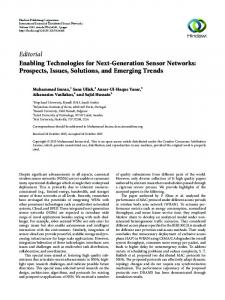
access network (RAN) element that is serving the end user. In UMTS this corresponds to the RNC, while in LTE this corresponds to the eNodeB. In this way, the rest of the CN elements can talk with the FrGW using the interfaces and protocols they already use to communicate with RNCs and eNodeBs. Similarly, the FrGW presents itself to the RAN as the CN element that is serving the user. In UMTS, this corresponds to the SGSN, while in LTE this corresponds to the S-GW and MME. In this way, the RAN can communicate with the FrGW using the interfaces and protocols it already uses to communicate with SGSNs, S-GW, and MME. Even though we have described the FR architecture using 3GPP’s terminology for UMTS and LTE, the FR is in no way constrained to be implemented just in these two radio access technologies (RATs). The previous descriptions can be mapped to other networks, such as WiMAX. It is because of this, that we have not gone in more detail regarding the specific protocols that will be used by the FR, since they would depend on the RAT in which it is introduced. 5. Performance evaluation In order to establish the merits of femtorelay’s performance gains, we developed a simulation environment utilizing OPNET, a high-fidelity wireless network simulation platform. OPNET provides wireless suite for 3G and 4G cellular systems that enables rapid development and optimization of wireless protocols and algorithms. Firstly, we developed a complete femtocell network modeling and development platform [50] with 3G femtocells (Home NodeB) and femtocell gateway (Home NodeB Gateway) implementing the necessary protocols required for femtocell operations. In a similar manner, we designed a complete femtorelay model, incorporating the novel functions of FrAP and FrGW in a 3G network. The internal architecture of the femtorelay is obtained utilizing the functional block diagram shown in Fig. 6 as a reference. Standard protocols have been utilized for the tunneling functions (GPRS tunneling protocol), radio layers on both the air interfaces (including RRC, PDCP, MAC, and PHY) and other related protocols. Both the femtocell and femtorelay models have been developed complying with the process and element definitions established by 3GPP standards while implementing their novel functions. The network topology of the femtorelay OPNET model is shown in Fig. 8. To evaluate the performance, extensive simulations were conducted for femtorelay to determine the throughput compared with closed-access (CSG) femtocells. Simulations were performed using different configurations by varying the transmit power of the access points, user distances, and traffic types, and results were obtained. In this paper, we present our initial results where the throughput of MUs and FUs data transmission have been measured to see how they are affected when both users are in close proximity and transmit simultaneously under—(1) CSG femtocells and (2) femtorelay. The user locations are assumed to be randomly distributed within the coverage area of the access points. The simulation parameters are listed in Table 1. The throughput performance of femtocells is computed as a percentage of the data transmission rate and is
10
I.F. Akyildiz et al. / Physical Communication 9 (2013) 1–15
the throughput of the MUs remains as high as 90%. Once the MUs traffic flow comes to an end, the FUs are able to achieve about 90% throughput. In the case of Fig. 9(b), the FUs start the transmission first and are able to achieve 90% throughput only as long as the MUs have not started transmitting their data. When both MUs and FUs are transmitting simultaneously, the throughputs for both the MUs and FUs drop significantly. A different throughput performance is observed in Fig. 9(c) where the throughput of MUs drops to 30%, while the FUs’ throughput remains close to 90%. As seen from these results, the cross-tier interference has a significant role in the achievable performance in the network where CSG femtocells are present. In Fig. 10, two scenarios where FR distance from the MUs and FUs vary are shown to highlight the throughput performance. It can be observed that in both the scenarios corresponding to Fig. 10(a) and (b), both the MUs and FUs achieve more than 90% throughput during the entire simulation time. In addition to the throughput vs. time computation, the mean total throughputs for both femtocells and femtorelay are computed and illustrated in Fig. 10(c). When the cross-tier interference is high for the case of femtocells, the mean total throughput is only about 30% as observed for femtorelay. When the interference in the case of femtocells is low due to the user distances, the femtorelay still achieves 1.5x higher mean total throughput than CSG femtocells. These results indicate clearly that femtorelays are a strong candidate to overcome the cross-tier interference that inhibits the throughput performance in small cells, and particularly in femtocells.
Fig. 8. Femtorelay simulation network topology. Table 1 Simulation parameters. User traffic type User start times User finish times BER required User traffic rate Mean user distance
CBR [100, 200] s [700, 1000] s 10−3 100 kbps 5m
illustrated in Fig. 9. In Fig. 9(a), the FUs start their transmission ahead of the MUs. As soon as the MUs start their transmission, the throughput for the FUs drops to zero, while
(a) FU throughput degradation.
(b) FU and MU throughput degradation.
(c) Partial FU throughput degradation. Fig. 9. Throughput performance under femtocell.
I.F. Akyildiz et al. / Physical Communication 9 (2013) 1–15
(a) Scenario 1.
11
(b) Scenario 2.
(c) Mean total throughput for femtorelay vs. femtocell. Fig. 10. Throughput performance under femtorelay.
5.1. Self-interference cancellation performance To evaluate the performance of the femtorelay’s selfinterference cancellation, we used MATLAB to simulate a feedback channel and an adaptive active cancellation mechanism. The performance of any self-interference cancellation scheme can be measured by attenuation power across a certain bandwidth. Adjacent channel power (ACP) and intermodulation intercept points (IIP) are also factors in measuring a receiver’s performance, which remain part of future work on this concept. The required performance differs by application. In the case of the FrAP, 3G and 4G cellular networks are of interest. For example, for E WCDMA, the minimum Nb , where Ni denotes interference i plus noise, required for a receiver to handle voice calls is approximately 7 dB. With a processing gain of 25 dB and received signal power, PR,DPCH , of −117 dBm, the combined power from self-interference, receiver noise, and nearby transmitters must be less than approximately −99 dBm in order to satisfy this requirement [81]. Fig. 11 shows the simulated performance of the femtorelay’s novel active self-interference cancellation scheme when transmitting a WCDMA signal, and the self-interference signal is drastically reduced across 5 MHz. Together with path loss and passive interference power reduction, femtorelay can act as a full-duplex node. In the time domain, the adaptive nature of the cancellation is apparent. Future work includes increasing the convergence rate and over interference attenuation power, as well as implementation on software defined radios for hardware validation.
6. Technology evolution for large scale indoor environments Femtocells were initially envisioned as devices installed by home users in their dwellings. As femtocells evolved, they were introduced in larger indoor environments such as airports, office buildings, shopping malls, and stadiums in order to improve both capacity and coverage. Nevertheless, the fact that the femtocells are now confined in a larger indoor environment does not eliminate the interference and congestion problems associated with them. With this in mind, we further expanded the femtorelay concept to attack these two problems in larger indoor environments (enterprise environments from now on). The multi-femtorelay (MFR) is the femtorelay version for enterprise environments [13]. The idea behind it is to have a central entity in charge of managing and coordinating the femtocells belonging to the enterprise environment, therefore, being closely located. Through this, it is able to provide better resource management across the femtocells compared to uncoordinated and distributed management approaches. While the concept of having a central entity managing multiple femtocells can be mapped to the femtocell gateway (HNB-GW or HeNB-GW in 3GPP terms), the MFR differs in three things. First, the femtocell gateway is meant to be part of the CN of the service provider, while the central entity in the MFR is meant to be located within the local premises of the enterprise environment. This leads to the second difference: in the MFR, the central entity is
12
I.F. Akyildiz et al. / Physical Communication 9 (2013) 1–15
(a) RRd-C.
(b) FRd-C. Fig. 12. MFR components.
Fig. 11. Active self-interference cancellation performance.
in charge of managing a small set of femtocells (i.e. just the ones of the enterprise environment), compared to the number of femtocells that are managed by femtocell gateway. This allows the MFR to optimize the performance of the enterprise femtocell networks in ways that are computationally prohibitive for the HNB-GW to apply to all the femtocells in the network. Third, and what makes it unique, is that the central entity in the MFR has the same type of wired and wireless backhaul as the femtorelay and brings all the benefits of the femtorelay to enterprise environments. Fig. 12 illustrates the main components of an MFR. First, there is the Relay Radio Component (RRd-C). The main tasks associated with the RRd-C are to coordinate the usage of resources among the FRd-C and to provide both wireless and wired backhaul to the CN using similar methods as the femtorelay. The second element is the Femto Radio Component (FRd-C). The main role of the FRd-C is to provide radio access to the MUs and FUs within the enterprise environment. The link between the RRd-C and the FRd-C can be done through a wired connection or through wireless connection, depending on the scenario. For example, in an office building the existing LAN can be used to connect the FRd-C to the RRd-C, as shown in Fig. 13. In tunnels and stadiums, wireless links may be more appropriate if there are no pre-existing wired networks. Regarding the internet-based backhaul, the RRd-C, the
Fig. 13. MFR: scenarios.
FRd-C or both may have it. For example, if all the FRd-C belong to the same owner, having the internet-based backhaul in the RRd-C is sufficient. However, if each FRd-C belongs to a different owner, then each FRd-C may have its own internet-based backhaul. From the point of view of procedures, interfaces, and protocols, the MFR borrows these directly from the femtorelay. Therefore, it is able to integrate seamlessly into the network. In terms of managing the radio and backhaul resources, both the RRd-C and FRd-C have resource managers that closely interact and coordinate the resources that should be used by each element of the MFR. This coordination allows the MFR to achieve efficient configurations within the enterprise environment to achieve multiple objectives, such as capacity optimization, mobility robustness, load balancing, and energy savings. Currently, we are exploring the methods to perform the coordination
I.F. Akyildiz et al. / Physical Communication 9 (2013) 1–15
functionality of the MFR, while avoiding unnecessary overhead in the backhaul between the RRd-C and FRd-C. We are also exploring how the capacity of the relay backhaul of the RRd-C may affect the performance within the MFR, and methods to tackle it. 7. Conclusions The demand for ubiquitous and very high speed wireless communications has shifted the paradigm of cellular networks to an architecture of heterogeneous networks composed of a combination of small cells and macrocells. Nevertheless, interference and backhaul issues still hinder the gains achievable through existing small cell technologies. To tackle these issues, a novel solution for next generation small cells, the femtorelay, has been introduced. The internal architecture has been described, as well as how this technology seamlessly integrates into existing 3G and 4G cellular networks. In addition, performance results have been provided, depicting the potential of this technology to outperform existing solutions. Further evolution of this technology has also been described, as well as its applications in large scale indoor environments. Acknowledgments This material is based upon work supported by Fundación Caja Madrid and SENACYT. References [1] 4G Americas, 4G mobile broadband evolution: release 10, release 11 and beyond, Tech. Rep., Oct. 2012. [2] V. Chandrasekhar, J. Andrews, A. Gatherer, Femtocell networks: a survey, IEEE Communications Magazine 46 (9) (2008) 59–67. [3] I.F. Akyildiz, D.M. Gutierrez-Estevez, E. Chavarria-Reyes, The evolution to 4G cellular systems: LTE-advanced, Physical Communications (Elsevier) Journal 3 (4) (2010) 217–244. [4] Small Cell Forum, Small cells—what’s the big idea? Tech. Rep., Feb. 2012 [Online]. Available: http://www.smallcellforum.org/Files/File/ SCF-Small_Cells_White_Paper.pdf. [5] 3GPP, TS 25.467 UTRAN architecture for 3G Home Node B (HNB), Tech. Rep., Dec. 2012 [Online]. Available: http://www.3gpp.org/ftp/ Specs/html-info/25467.htm. [6] WMF-T33-118-R016v02: Network architecture femtocell core specification, Tech. Rep. [7] Visiongain, The small cell market 2012–2017, Tech. Rep., Oct. 2012. [8] Small Cell Forum, Small cell market status, Tech. Rep., Nov. 2012 [Online]. Available: http://smallcellforum.org/smallcellforum/ resources-white-papers. [9] T. Zahir, K. Arshad, A. Nakata, K. Moessner, Interference management in femtocells, IEEE Communications Surveys Tutorials 15 (1) (2013) 293–311. First quarter. [10] O. Tipmongkolsilp, S. Zaghloul, A. Jukan, The evolution of cellular backhaul technologies: current issues and future trends, IEEE Communications Surveys and Tutorials 13 (1) (2011) 97–113. First quarter. [11] P. Xia, V. Chandrasekhar, J. Andrews, Open vs. closed access femtocells in the uplink, IEEE Transactions on Wireless Communications 9 (12) (2010) 3798–3809. [12] A. Ghosh, N. Mangalvedhe, R. Ratasuk, B. Mondal, M. Cudak, E. Visotsky, T.A. Thomas, J.G. Andrews, P. Xia, H.S. Jo, H.S. Dhillon, T.D. Novlan, Heterogeneous cellular networks: from theory to practice, IEEE Communications Magazine 50 (6) (2012) 54–64. [13] I.F. Akyildiz, D.M. Gutierrez-Estevez, E. Chavarria-Reyes, Femtorelay systems and methods of managing same, US Patent Application No. 20 120 076 027, Pub. Mar. 29, 2012. [14] J.G. Andrews, H. Claussen, M. Dohler, S. Rangan, M.C. Reed, Femtocells: past, present, and future, IEEE Journal on Selected Areas in Communications 30 (3) (2012) 497–508.
13
[15] 3GPP, UTRAN overall description, Tech. Rep., Dec. 2012 [Online]. Available: http://www.3gpp.org/ftp/Specs/html-info/25401.htm. [16] 3GPP, TS 36.300 Evolved Universal Terrestrial Radio Access (EUTRA) and Evolved Universal Terrestrial Radio Access Network (E-UTRAN); overall description, Tech. Rep., Dec. 2012 [Online]. Available: http://www.3gpp.org/ftp/Specs/html-info/36300.htm. [17] 3GPP, TR 25.820 3G Home NodeB Study Item Technical Report, Tech. Rep., Sep. 2008 [Online]. Available: http://www.3gpp.org/ftp/ Specs/html-info/25820.htm. [18] M. Yavuz, F. Meshkati, S. Nanda, A. Pokhariyal, N. Johnson, B. Raghothaman, A. Richardson, Interference management and performance analysis of UMTS/HSPA+ femtocells, IEEE Communications Magazine 47 (9) (2009) 102–109. [19] Y. Tokgoz, F. Meshkati, Y. Zhou, M. Yavuz, S. Nanda, Uplink interference management for HSPA+ and 1xEVDO femtocells, in: Proc. of IEEE Global Telecommunications Conference, GLOBECOM, Dec. 2009, pp. 1–7. [20] G.W.O. da Costa, A.F. Cattoni, V.A. Roig, P.E. Mogensen, Interference mitigation in cognitive femtocells, in: Proc. of IEEE GLOBECOM Workshops, GC Wkshps, Dec. 2010, pp. 721–725. [21] D. Lopez-Perez, A. Valcarce, G. de la Roche, J. Zhang, OFDMA femtocells: a roadmap on interference avoidance, IEEE Communications Magazine 47 (9) (2009) 41–48. [22] H. de Lima Carlos, M. Bennis, K. Ghaboosi, M. Latva-aho, On interference analysis of self-organized femtocells in indoor deployment, in: Proc. of IEEE GLOBECOM Workshops, GC Wkshps, Dec. 2010, pp. 659–663. [23] F. Pantisano, M. Bennis, W. Saad, M. Debbah, M. Latva-aho, Interference alignment for cooperative femtocell networks: a gametheoretic approach, IEEE Transactions on Mobile Computing. Early access (in press). [24] M. Nazir, M. Bennis, K. Ghaboosi, A. MacKenzie, M. Latva-aho, Learning based mechanisms for interference mitigation in selforganized femtocell networks, in: Conference Record of Asilomar Conference on Signals, Systems and Computers, ASILOMAR, Nov. 2010, pp. 1886–1890. [25] R. Pabst, B.H. Walke, D.C. Schultz, P. Herhold, H. Yanikomeroglu, S. Mukherjee, H. Viswanathan, M. Lott, W. Zirwas, M. Dohler, H. Aghvami, D.D. Falconer, G.P. Fettweis, Relay-based deployment concepts for wireless and mobile broadband radio, IEEE Communications Magazine 42 (9) (2004) 80–89. [26] J. Sydir, R. Taori, An evolved cellular system architecture incorporating relay stations, IEEE Communications Magazine 47 (6) (2009) 115–121. [27] 3GPP, TR 36.806 Evolved Universal Terrestrial Radio Access Network (E-UTRA); relay architectures for E-UTRA (LTE-Advanced), Tech. Rep., Apr. 2010 [Online]. Available: http://www.3gpp.org/ftp/Specs/ html-info/36806.htm. [28] K. Loa, C.-C. Wu, S.-T. Sheu, Y. Yuan, M. Chion, D. Huo, L. Xu, IMT-advanced relay standards [WiMAX/LTE update], IEEE Communications Magazine 48 (8) (2010) 40–48. [29] S.W. Peters, A.Y. Panah, K.T. Truong, R.W. Heath, Relay Architectures for 3GPP LTE-Advanced, EURASIP Journal on Wireless Communications and Networking (1) (2009) 618787. [30] Y. Yang, H. Hu, J. Xu, G. Mao, Relay technologies for WiMax and LTE-advanced mobile systems, IEEE Communications Magazine 47 (10) (2009) 100–105. [31] B. Kwon, Y. Chang, J.A. Copeland, A network entry protocol and an OFDMA symbol allocation scheme for non-transparent relay stations in IEEE 802.16j MMR networks, in: Proc. of IEEE Military Communications Conference, MILCOM, Nov. 2008, pp. 1–6. [32] A. Sayenko, O. Alanen, H. Martikainen, Analysis of the nontransparent in-band relays in the IEE 802.16 multi-hop system, in: Proc. of IEEE Wireless Communications and Networking Conference, WCNC, Apr. 2010, pp. 1–6. [33] R. Yusoff, M.D. Dani Baba, R. Abd Rahman, M. Ibrahim, N. Mat Isa, Performance analysis of transparent and non-transparent relays in MMR WiMAX networks, in: Proc. of IEEE Symp. Industrial Electronics and Applications, ISIEA, Sep. 2011, pp. 237–240. [34] D. Zhou, W. Song, Interference-controlled load sharing with femtocell relay for macrocells in cellular networks, in: Proc. of IEEE Global Telecommunications Conference, GLOBECOM, Dec. 2011, pp. 1–5. [35] P. Jacob, A. Madhukumar, Interference reduction through femtorelays, Communications, IET 6 (14) (2012) 2208–2217. [36] P. Jacob, A.S. Madhukumar, Femto-relays: a power efficient coverage extension mechanism for femtocells, in: Proc. of IEEE Int. Symp. on Personal Indoor and Mobile Radio Communications, PIMRC, Sep. 2011, pp. 975–979.
14
I.F. Akyildiz et al. / Physical Communication 9 (2013) 1–15
[37] T. Elkourdi, O. Simeone, Femtocell as a relay: an outage analysis, IEEE Transactions on Wireless Communications 10 (12) (2011) 4204–4213. [38] A. Rath, S. Hua, S.S. Panwar, FemtoHaul: using femtocells with relays to increase macrocell backhaul bandwidth, in: Proc. of IEEE Conference on Computer Communications, INFOCOM Workshops, Mar. 2010, pp. 1–5. [39] S. Samarakoon, M. Bennis, W. Saad, M. Latva-aho, Enabling relaying over heterogeneous backhauls in the uplink of femtocell networks, in: Proc. of Int. Symp. on Modeling and Optimization in Mobile, Ad Hoc and Wireless Networks, WiOpt, May 2012, pp. 75–80. [40] Y.-S. Chen, C.-C. Li, W.-L. Chiang, A femtocell-assisted data forwarding protocol in relay enhanced LTE networks, in: Proc. of Int Parallel Processing Workshops, ICPPW Conference, Sep. 2011, pp. 127–136. [41] A.T. Gamage, N. Rajatheva, M. Codreanu, Resource allocation for OFDMA-based relay assisted two-tier femtocell networks, in: Proc. of Int Wireless Communication Systems, ISWCS Symp., Nov. 2011, pp. 834–838. [42] N. Nomikos, P. Makris, D.N. Skoutas, D. Vouyioukas, C. Skianis, A cooperation framework for LTE femtocells’ efficient integration in cellular infrastructures based on femto relay concept, in: Proc. of IEEE Int. Computer Aided Modeling and Design of Communication Links and Networks, CAMAD Workshop, Sep. 2012, pp. 318–322. [43] D. Knisely, T. Yoshizawa, F. Favichia, Standardization of femtocells in 3GPP, IEEE Communications Magazine 47 (9) (2009) 68–75. [44] D. Knisely, F. Favichia, Standardization of femtocells in 3GPP2, IEEE Communications Magazine 47 (9) (2009) 76–82. [45] N. Krishnan, R.D. Yates, N.B. Mandayam, J.S. Panchal, Bandwidth sharing for relaying in cellular systems, IEEE Transactions on Wireless Communications 11 (1) (2012) 117–129. [46] C. Raman, G.J. Foschini, R.A. Valenzuela, R.D. Yates, N.B. Mandayam, Half-duplex relaying in downlink cellular systems, IEEE Transactions on Wireless Communications 10 (5) (2011) 1396–1404. [47] H.-S. Jo, P. Xia, J.G. Andrews, Downlink femtocell networks: open or closed? in: Proc. IEEE Int. Communications Conference, ICC, Jun. 2011, pp. 1–5. [48] S.-Y. Yun, Y. Yi, D.-H. Cho, J. Mo, The economic effects of sharing femtocells, IEEE Journal on Selected Areas in Communications 30 (3) (2012) 595–606. [49] D.M. Gutierrez-Estevez, B. Canberk, I.F. Akyildiz, Spatio-temporal estimation for interference management in femtocell networks, in: Proc. of IEEE Int. Symp. on Personal, Indoor and Mobile Radio Comm. Systems, PIMRC, Sep. 2012, pp. 1137–1142. [50] E. Chavarria-Reyes, D. Gutierrez-Estevez, I. Akyildiz, A complete femtocell network modeling and development platform, in: Proc. of IEEE Global Telecommunications Conference, GLOBECOM, Dec. 2012. [51] E. Bernal-Mor, V. Pla, D.M. Gutierrez-Estevez, J. Martinez-Bauset, Resource management for macrocell users in hybrid access femtocells, in: Proc. of IEEE Global Telecommunications Conference, GLOBECOM, Dec. 2012. [52] D. Lopez-Perez, I. Guvenc, G. de la Roche, M. Kountouris, T.Q.S. Quek, J. Zhang, Enhanced intercell interference coordination challenges in heterogeneous networks, IEEE Wireless Communications Magazine 18 (3) (2011) 22–30. [53] H.-S. Jo, C. Mun, J. Moon, J.-G. Yook, Interference mitigation using uplink power control for two-tier femtocell networks, IEEE Transactions on Wireless Communications 8 (10) (2009) 4906–4910. [54] T. Guo, A. ul Quddus, R. Tafazolli, Seamless handover for LTE macro-femto networks based on reactive data bicasting, IEEE Communications Letters 16 (11) (2012) 1788–1791. [55] T. Guo, A. ul Quddus, N. Wang, R. Tafazolli, Local mobility management for networked femtocells based on X2 traffic forwarding, IEEE Transactions on Vehicular Technology 62 (1) (2013) 326–340. [56] R. Singoria, T. Oliveira, D.P. Agrawal, Reducing unnecessary handovers: call admission control mechanism between WiMAX and femtocells, in: Proc. of IEEE Global Telecommunications Conference, GLOBECOM, Dec. 2011, pp. 1–5. [57] D.W.K. Ng, R. Schober, Dynamic resource allocation in OFDMA systems with full-duplex and hybrid relaying, in: Proc. of IEEE Int. Communications Conference, ICC, Jun. 2011, pp. 1–6. [58] Y.Y. Kang, J.H. Cho, Capacity of MIMO wireless channel with fullduplex amplify-and-forward relay, in: Proc. of IEEE Int. Symp. on Personal, Indoor and Mobile Radio Communications, PIMRC, Sep. 2009, pp. 117–121. [59] T. Riihonen, S. Werner, R. Wichman, Comparison of full-duplex and half-duplex modes with a fixed amplify-and-forward relay, in: Proc. of IEEE Wireless Communications and Networking Conference, WCNC, Apr. 2009, pp. 1–5.
[60] T. Riihonen, S. Werner, R. Wichman, Hybrid full-duplex/half-duplex relaying with transmit power adaptation, IEEE Transactions on Wireless Communications 10 (9) (2011) 3074–3085. [61] Q. Li, K.H. Li, K.C. Teh, Achieving optimal diversity-multiplexing tradeoff for full-duplex MIMO multihop relay networks, IEEE Transactions on Information Theory 57 (1) (2011) 303–316. [62] V.R. Cadambe, S.A. Jafar, Degrees of freedom of wireless networks with relays, feedback, cooperation, and full duplex operation, IEEE Transactions on Information Theory 55 (5) (2009) 2334–2344. [63] A. Host-Madsen, J. Zhang, Capacity bounds and power allocation for wireless relay channels, IEEE Transactions on Information Theory 51 (6) (2005) 2020–2040. [64] P. Lioliou, M. Viberg, M. Coldrey, F. Athley, Self-interference suppression in full-duplex MIMO relays, in: Conf. Record of Asilomar Conference Signals, Systems and Computers, ASILOMAR, 2010, pp. 658–662. [65] H. Ju, E. Oh, D. Hong, Improving efficiency of resource usage in two-hop full duplex relay systems based on resource sharing and interference cancellation, IEEE Transactions on Wireless Communications 8 (8) (2009) 3933–3938. [66] T. Riihonen, S. Werner, R. Wichman, Mitigation of loopback selfinterference in full-duplex MIMO relays, IEEE Transactions on Signal Processing 59 (12) (2011) 5983–5993. [67] M. Duarte, C. Dick, A. Sabharwal, Experiment-driven characterization of full-duplex wireless systems, IEEE Transactions on Wireless Conmmunications 11 (12) (2012) 4296–4307. [68] A. Sahai, G. Patel, A. Sabharwal, Pushing the limits of full-duplex: design and real-time implementation, in: Rice University Technical Report TREE1104, http://arxiv.org/abs/1107.0607, Jun. 2011. [69] W. Schacherbauer, A. Springer, T. Ostertag, C.C.W. Ruppel, R. Weigel, A flexible multiband frontend for software radios using high IF and active interference cancellation, in: Proc. of IEEE MTT-S Int. Microwave Symp. Digest, Vol. 2, 2001, pp. 1085–1088. [70] The QHX220 by Intersil, 2013 [Online]. Available: http:// www.intersil.com/en/products/other-analog/noise-canceller/ isolation-enhancer-noise-cancellation/QHX220.html. [71] M. Duarte, A. Sabharwal, Full-duplex wireless communications using off-the-shelf radios: Feasibility and first results, in: Conf. Record of Asilomar Conference on Signals, Systems and Computers, ASILOMAR, Nov. 2010, pp. 1558–1562. [72] J.I. Choi, M. Jain, K. Srinivasan, P. Levis, S. Katti, Achieving single channel, full duplex wireless communication, in: Proc. of International Conference on Mobile computing and networking, MobiCom, 2010, pp. 1–12. [73] J. Yuan, J. Shi, B. Tang, H. Chen, An adaptive feedback interference cancelling algorithm based on independent component analysis for wireless repeaters, in: Proc. of Int. Conference on Wireless Communications Networking and Mobile Computing, WiCOM, Sep. 2010, pp. 1–4. [74] B. Widrow, J.R. Glover Jr., J.M. McCool, J. Kaunitz, C.S. Williams, R.H. Hearn, J.R. Zeidler, J. Eugene Dong, R.C. Goodlin, Adaptive noise cancelling: principles and applications, Proceedings of the IEEE 63 (12) (1975) 1692–1716. [75] 3GPP, TS 25.444 Iuh data transport, Tech. Rep., Sep. 2012 [Online]. Available: http://www.3gpp.org/ftp/Specs/html-info/25444.htm. [76] 3GPP, TS 25.468 UTRAN Iuh Interface RANAP User Adaption (RUA) signalling, Tech. Rep., Dec. 2012 [Online]. Available: http://www. 3gpp.org/ftp/Specs/html-info/25468.htm. [77] 3GPP, TS 25.469 UTRAN Iuh interface Home Node B (HNB) Application Part (HNBAP) signalling, Tech. Rep., Jun. 2012 [Online]. Available: http://www.3gpp.org/ftp/Specs/html-info/25469.htm. [78] 3GPP, TS 36.420 Evolved Universal Terrestrial Radio Access Network (E-UTRAN); X2 general aspects and principles, Tech. Rep., Sep. 2012 [Online]. Available: http://www.3gpp.org/ftp/Specs/html-info/ 36420.htm. [79] 3GPP, TS 36.410 Evolved Universal Terrestrial Radio Access Network (E-UTRAN); S1 general aspects and principles, Tech. Rep., Sep. 2012 [Online]. Available: http://www.3gpp.org/ftp/Specs/htmlinfo/36410.htm. [80] 3GPP, TS 25.410 UTRAN Iu interface: General aspects and principles, Tech. Rep., Sep. 2012 [Online]. Available: http://www.3gpp.org/ftp/ Specs/html-info/25410.htm. [81] O.K. Jensen, T.E. Kolding, C.R. Iversen, S. Laursen, R.V. Reynisson, J.H. Mikkelsen, E. Pedersen, M.B. Jenner, T. Larsen, RF receiver requirements for 3G W-CDMA mobile equipment, Microwave Journal 43 (2) (2000) 22.
I.F. Akyildiz et al. / Physical Communication 9 (2013) 1–15 Ian F. Akyildiz received the B.S., M.S., and Ph.D. degrees in Computer Engineering from the University of Erlangen-Nürnberg, Germany, in 1978, 1981 and 1984, respectively. Currently, he is the Ken Byers Chair Professor in Telecommunications with the School of Electrical and Computer Engineering, Georgia Institute of Technology, Atlanta, the Director of the Broadband Wireless Networking Laboratory and Chair of the Telecommunication Group at Georgia Tech. Dr. Akyildiz is an honorary professor with the School of Electrical Engineering at Universitat Politècnica de Catalunya (UPC) in Barcelona, Catalunya, Spain, and the founder of N3Cat (NaNoNetworking Center in Catalunya). He is also an honorary professor with the Department of Electrical, Electronic and Computer Engineering at the University of Pretoria, South Africa and the founder of the Advanced Sensor Networks Lab. Since 2011, he is a Consulting Chair Professor at the Department of Information Technology, King Abdulaziz University (KAU) in Jeddah, Saudi Arabia. Since January 2013, Dr. Akyildiz is also a FiDiPro Professor (Finland Distinguished Professor Program (FiDiPro) supported by the Academy of Finland) at Tampere University of Technology, Department of Communications Engineering, Finland. He is the Editorin-Chief of Computer Networks (Elsevier) Journal, and the founding Editor-in-Chief of the Ad Hoc Networks (Elsevier) Journal, the Physical Communication (Elsevier) Journal and the Nano Communication Networks (Elsevier) Journal. He is an IEEE Fellow (1996) and an ACM Fellow (1997). He received numerous awards from IEEE and ACM. His current research interests are in nanonetworks, Long Term Evolution (LTE) advanced networks, cognitive radio networks and wireless sensor networks.
Elías Chavarría Reyes received the B.E. degree in Electronics and Communication Engineering from Universidad de Panamá, Ciudad de Panamá, Panamá, in 2007. He received his M.S. degree in Electrical and Computer Engineering from the School of Electrical and Computer Engineering, Georgia Institute of Technology, Atlanta, in 2010. Currently, he is pursuing his Ph.D. degree in the Broadband Wireless Networking Laboratory, School of Electrical and Computer Engineering, Georgia Institute of Technology, Atlanta, with a fellowship from ‘‘SENACYT’’. His current research is focused on Heterogeneous Networks and Self-Organizing Networks. He is a student member of IEEE.
15
David M. Gutiérrez-Estévez obtained his Engineering Degree in Telecommunications from Universidad de Granada, Spain, in July 2009. During the summer of 2007 he held an internship position at the Audio Department of Fraunhofer Institute for Integrated Circuits in Erlangen, Germany. From April 2008 to June 2009 he was a research assistant within the Broadband Mobile Communications Networks Department of the Fraunhofer Heinrich Hertz Institute in Berlin, where he worked on projects linked to Long Term Evolution (LTE) cellular systems. He received his M.S. degree in Electrical and Computer Engineering from Georgia Tech in 2011 with a fellowship from Fundación la Caixa. Currently, he is pursuing his Ph.D. degree at the Broadband Wireless Networking Laboratory at Georgia Tech under the supervision of Dr. Ian. F. Akyildiz with a fellowship from Fundación Caja Madrid. Ravikumar Balakrishnan obtained the B.E. Degree in Electronics and Communication Engineering from Anna University, India, in 2009 and the M.S. Degree from the School of Electrical and Computer Engineering, Georgia Institute of Technology, Atlanta, in 2011. Currently, he is pursuing his Ph.D. degree in the Broadband Wireless Networking Laboratory, School of Electrical and Computer Engineering, Georgia Institute of Technology, Atlanta. Mr. Balakrishnan held an internship position at the Wireless Technology Division, Intel Corporation focusing on next generation cellular network architecture and protocols. His areas of research include Next Generation Cellular Networks and Cognitive Radio Networks. He is a student member of IEEE. John R. Krier obtained B.S. degrees for Electrical and Computer Engineering from North Carolina State University in 2010 with concentrations in Telecommunication and Digital Signal Processing. He received his M.S. degree for Electrical Engineering in 2011 from Georgia Institute of Technology. Currently, he is a Ph.D. student at Georgia Tech, in the Broadband Wireless Networking Lab under the supervision of Dr. Ian F. Akyildiz. His current research is focused on Next-Generation Wireless Networks and Cognitive Radio Networks. He is a student member of IEEE.