Enabling Scientific Workflow Reuse through Structured Composition of. Dataflow and Control-Flow. Shawn Bowers. UC Davis Genome Center. University of ...
Enabling Scientific Workflow Reuse through Structured Composition of Dataflow and Control-Flow Shawn Bowers UC Davis Genome Center University of California, Davis Anne H.H. Ngu Department of Computer Science Texas State University-San Marcos
Abstract Data-centric scientific workflows are often modeled as dataflow process networks. The simplicity of the dataflow framework facilitates workflow design, analysis, and optimization. However, modeling “control-flow intensive” tasks using dataflow constructs often leads to overly complicated workflows that are hard to comprehend, reuse, and maintain. We describe a generic framework, based on scientific workflow templates and frames, for embedding control-flow intensive subtasks within dataflow process networks. This approach can seamlessly handle complex control-flow without sacrificing the benefits of dataflow. We illustrate our approach with a real-world scientific workflow from the astrophysics domain, requiring remote execution and file transfer in a semi-reliable environment. For such workflows, we also describe a 3-layered architecture based on frames and templates where the top-layer consists of an overall dataflow process network, the second layer consists of a tranducer template for modeling the desired control-flow behavior, and the bottom layer consists of frames inside the template that are specialized by embedding the desired component implementation. Our approach can enable scientific workflows that are more robust (faulttolerance strategies can be defined by control-flow driven transducer templates) and at the same time more reusable, since the embedding of frames and templates yields more structured and modular workflow designs.
1
Introduction
Scientific workflow systems [21, 22, 23, 26] are increasingly being used by scientists to construct and execute com-
Bertram Lud¨ascher Deptartment of Computer Science UC Davis Genome Center University of California, Davis Terence Critchlow Center for Applied Scientific Computing Lawrence Livermore National Laboratory
plex scientific analyses. Such analyses are typically datacentric and involve “gluing” together data retrieval, computation, and visualization components into a single executable analysis pipeline. The components may be part of the workflow system, part of another application (invoked through system calls, executing R or M ATLAB scripts, etc.), or even external, accessed via web or grid services. In addition to providing scientists with a mechanism to compose and configure otherwise heterogeneous components, scientific workflow systems aim to support end-to-end workflow management, e.g., through tools for accessing external data sources, archival of intermediate results, and monitoring of workflow execution. One common approach is to model scientific workflows as directed acyclic graphs (DAGs), where arcs denote scheduling dependencies between computation tasks called jobs [29, 7]. For example, scheduling these job-based workflows amounts to queueing and executing jobs based on the partial order induced by the DAG. Alternatively, a number of scientific workflow systems have adopted a more expressive language for modeling scientific workflows based on dataflow process networks [19, 15], a model of computation that comes with “built-in” support for stream-based and concurrent execution.1 Dataflow is a natural paradigm for data-driven and dataintensive scientific workflows such as, e.g., the terabytesized Fusion Plasma Simulation [3] and the Terascale Supernova Initiative [31]. Workflows expressed using dataflow process networks can be efficiently analysed and scheduled [17], and are also a simple and intuitive model for workflow designers [4]. However, while dataflow has become a standard model of scientific workflows, some 1 Workflows modeled in this way are also not limited to DAGs, i.e., they can contain loops.
amount of control-flow modeling is often necessary for engineering fault-tolerant, robust, and adaptive workflows. Here, control-flow refers to the use of constructs such as branching via if-then-else and switch-case statements, and iteration with multiple entry and exit points. Another reason for the use of control-flow constructs concerns the handling of complex data structures, often found in scientific applications. In particular, workflows must often “build in” support for accessing, combining, and manipulating portions of these data structures explicitly. Connecting independently created components (e.g., different web-services or applications created by different organizations) offers similar challenges, requiring additional subprocesses to align component input and output data structures (schemas) [4]. These differences in structure can be complex, e.g., involving different levels of representation granularity and requiring structural transformations. In this paper, we address the problem of combining dataflow and control-flow for scientific workflows. It has been noted [20] that modeling control-flow using only dataflow constructs can quickly lead to overly complex workflows that are hard to understand, reuse, reconfigure, maintain, and schedule [17]. In particular, modeling control-flow using dataflow involves inserting and linking various lowlevel and specialized control components alongside dataflow components, thus making it difficult to distinguish control-flow from dataflow aspects (since they are “entangled”). The organization and contributions of the paper are as follows: We describe a framework that “untangles” dataflow and control-flow aspects and instead supports a structured embedding of control-intensive subtasks within dataflow process networks (Section 2). Our approach is to encapsulate generic behavioral specifications (i.e., controlflow) in workflow templates. Templates are distinct and separate components and thus can be easily reused in other workflows. Templates are partial specifications and contain “holes”, so-called frames, that act as placeholders for independently defined subcomponents. Composing templates with existing dataflow components results in applying the associated behavior to the component in such a way that the separation between control-flow and dataflow is maintained, thus allowing the underlying dataflow component to be easily changed (typically through a configuration parameter of the template). This approach allows workflow designers to change complex control-flow behavior by simply using different templates. Our approach was inspired by the notion of hierarchical finite state machines [11] and can also be seen as an extension of actor-oriented modeling [18] with frames and templates (Figure 2). In Section 3 we first present a specialized 3-layered architecture of our framework. It allows the designer to select and reuse different control-flow intensive behaviors for
generic top-level components, by embedding inside of them suitable transducer templates as the middle-layer. The concrete implementation of frames inside of transducer templates is independently selected via the bottom-layer. We then describe a Generic Data Transfer (GDT) component, which has been implementated on top of the opensource K EPLER system [21], an extension of P TOLEMY II [5] for scientific workflows. The GDT component was motivated by earlier work on a control-intensive astrophysics workflow [31]. As shown in Figure 1, this workflow uses dataflow constructs to implement a fault-tolerance scheme (involving “retry”) for transfering files, resulting in a very complex process network. In the new approach, the GDT component encapsulates this and other transfer behaviors as templates in which workflow designers can select from a set of behaviors as well as the desired underlying transfer protocols (e.g., scp, ftp, or using SRB [28]). Given a particular behavior and protocol, the GDT automatically composes these into the desired executable component. At any time, the behavior and the underlying protocols can be easily changed by simply reconfiguring GDT. In the original workflow this would be a complex and error-prone programming task, involving the insertion, deletion, and rewiring of various control-flow and dataflow components. In Section 3 we also describe a Generic remote eXecution (GX) component, whose middle-layer employs exactly the same control-intensive behaviors (via transducer templates) as GDT to support fault-tolerance, demonstrating the versatility of our approach and the improved component reusability it creates. Finally, we describe related work in Section 4 and conclude in Section 5.
2
Actor-Oriented Design Extensions
In K EPLER, users develop workflows by selecting appropriate components called actors and placing them on a design canvas, after which they can be “wired” together to form the desired workflow graph (cf. Figure 1). Actors have input and output ports which provide the communication interface to other actors. Workflows can be hierarchically structured, yielding composite actors that encapsulate subworkflows (e.g., see the bottom-right in Figure 1). A novel feature of K EPLER, inherited from P TOLEMY II, is that the overall execution and component interaction semantics of a workflow is not defined by the components, but is factored out into a separate component called a director. Taken together, workflows, actors, ports, connections, and directors represent the basic building blocks of actor-oriented modeling and design [18]. In this section we define scientific workflows as dataflow process networks and describe two extensions to actororiented modeling, i.e., frames and templates. Frames form
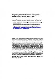
Figure 1. Control-flow intensive astrophysics workflow in K EPLER [31]. “Retry”, a composite actor for fault-tolerant data transfer (top), contains a subworkflow (bottom), which itself contains a “ConditionalLoop” subworkflow (inside not shown). Complex feedback loops and the use of boolean switches illustrate the complexity of modeling control-flow directly in a dataflow process network.
the basis of our approach for embedding control-flow intensive behaviors (via workflow templates) inside of dataflow process networks.
2.1
Scientific Workflows as Process Networks
An actor-oriented workflow graph W = hA, Di consists of a set A of actors representing components or tasks and a set of directed dataflow connections D (see below), representing communication channels that connect actors via ports, and along which actors communicate by passing tokens. Let ports(A) denote the set of ports of actor A. Each port p ∈ ports(A) is designated as either input or output. Some input ports may be distinguished as parameters pars(A) ⊆ in(A) which can be used for configuring A’s behavior. For convenience, we write A.p to emphasize that port p belongs to actor A. The signature ΣA of an actor is given by its ports; we write ΣA = in(A) → out(A). Actors are wired together through their ports via dataflow connections. A dataflow connection d ∈ D is a directed hyperedge d = ho, ii, connecting n output ports o = {o1 , . . . , on } with m input ports i = {i1 , . . . , im }. A
dataflow connection d = ho, ii corresponds to a merge step of output tokens from o, followed by a copy step, delivering all tokens to the input ports i. A composite actor AW encapsulates a sub-workflow W . The (external) ports of AW consist of a distinguished set of ports from W , i.e., AW might not expose all of its subworkflow’s ports. A hierarchical workflow is a workflow graph that contains at least one composite actor. Since subworkflows can themselves be hierarchical, any level of nesting can be modeled. A port p may have a structural data type constraining the allowed set of values accepted by p (if p is an input port) or produced by p (if p is an output port). The P TOLEMY II type system includes simple types (e.g., string and int) and complex types (such as nested record and list structures). A port p may also have a semantic type, denoting a concept from a description logic ontology [4]. For example, a semantic type is: M EASUREMENT u ∀ITEM.S PECIES O CCURRENCE indicating that the corresponding port accepts (or produces) data tokens that denote measurements where the measured
item is a species occurrence (as opposed to, e.g., a temperature). In addition to port semantic types, an actor A itself may also be associated with a semantic type, describing the overall function or purpose of A.While structural (i.e., data) type safety ensures that actors can “work with” incoming data tokens at runtime, semantic type safety avoids actor connections at design time that are not meaningful in terms of their concept annotations (e.g., occurrence data cannot be used where temperature data is expected). So far, the execution semantics of a workflow graph W has not been specified. Indeed, in P TOLEMY II and thus in K EPLER, the workflow designer can choose among different models of computation, each one being represented by a so-called director. A director specifies and mediates all inter-actor communication, separating workflow orchestration and scheduling (the director’s concern) from individual actor execution (the actor’s concern). This separation achieves a form of behavioral polymorphism [18], resulting in more reusable actor components and subworkflows. K EPLER (through P TOLEMY II) provides a variety of directors that implement process network (PN and SDF), discrete event (DE), continuous time (CT), and finite state transducer (FST) semantics. In PN, e.g., the director executes each actor in a workflow as a separate process (or thread). Connections (or channels) are used to send (i.e., stream) sequences of data tokens between actors, and actors map input sequences to output sequences. Actors communicate asynchronously in process networks through buffered channels implemented as queues of effectively unbounded size. Thus, the PN director can be used to pipeline data tokens through scientific workflows, enabling highly concurrent execution.
2.2
Frames
Actors in actor-oriented modeling and design are always concrete: they correspond to particular implementations and can be directly executed in a workflow. We extend actor-oriented modeling with a new entity called frame, which is an abstraction that denotes a set of alternative actor implementations (or templates) with similar, but not necessarily identical functionality.2 For workflow designers, frames are placeholders for components that will be instantiated and specialized later. Thus, a designer can place a frame F on the design canvas, and connect it with other workflow components, without prematurely specifying which component C is to be used. For component developers, frames can be used as abstractions for a family of components (actors or templates) with similar function. Formally, a frame is a named entity F that acts as a 2 Here the term frame symbolizes a notion akin to a picture frame— allowing different “pictures” (i.e., components) so long as they conform to the constraints imposed by the “frame.”
F C
a). Embedding F[C]
T
F1 F2
b). Workflow Template T(F1,F2)
t1
FST
F
t3
T
t2
c). Transducer Template T(F)
Figure 2. a) Embedding of component C in frame F; b) workflow template T(F1 ,F2 ); c) finite state transducer template T(F).
placeholder for a component C to be “plugged into” F (see Figure 2 a). When devising a frame F , a family of components CF is envisioned, with each C ∈ CF being a possible alternative for embedding into F . Like an actor, a frame has input, output, and parameter ports, structural types, and semantic types; taken together they form the frame signature ΣF . This signature represents the common API of the family CF of components that F abstracts. An embedding F [C] of a component C into a frame F is a set of pairs associating (or “wiring”) ports of C with ports of F , i.e., F [C] ⊆ ports(F ) × ports(C). We indicate the wiring type of a pair (x, y) ∈ F [C] as follows: • F.x I C.y; if x ∈ in(F ), y ∈ in(C) • F.x J C.y; if x ∈ out(F ), y ∈ out(C)
(input) (output)
• F.x H C.y; if x ∈ pars(F ), y ∈ pars(C) (parameter) The embedded component C may also introduce new ports not in ports(F ). We denote these ports as BC.y, CC.y, and OC.y for input, output, and parameter ports y, respectively. Similarly, an embedding F [C] may not use all the ports of C. We denote these unused ports as F.xC, F.xB, and F.xO for input, output, and parameter ports x, respectively. We note that parameter ports F.x can also be connected to input ports C.y and vice versa. However, other connection
types (x, y) ∈ F [C] are not allowed. Here we assume that all the ports of F are used in the embedding. An embedding F [C] is well-formed if the input and output port directions are observed, i.e., F ’s inputs (outputs) are wired only to inputs (outputs) of C (Figure 2 a). A well-formed embedding F [C] is structurally well-typed if the structural types align, and semantically well-typed if the semantic types align. We require for each connection between a port of F and a port of C having (structural or semantic) types τF and τC that: (1) τF � τC for input structural types; (2) τC � τF for output structural types; (3) τF v τC for input semantic types; and (4) τC v τF for output semantic types.3 Thus, we use contra-variant subtyping for both structural and semantic types: when embedding a component C in a frame F , C should be able to handle F 0 s inputs. Conversely, F should be able to handle outputs of C (or, equivalently, C should not produce output that is more general than what F anticipates). The signature ΣF [C] after embedding C in F includes (unless specified otherwise by the designer) the ports of F plus the new ports introduced by C. In some cases, the above typing rules can be “loosened” when the frame occurs within a workflow. In particular, if an input port of F is connected to the output port of an actor having a type τA � τF (similarly, τA v τF ), then we only require for a corresponding input port of C that τA � τC (similarly, τA v τC ). Thus, it may be possibly that τC ≺ τF if τA ≺ τF (and similarly, τC @ τF if τA @ τF ). This situation is only possible when F has such a “context,” i.e., is part of a larger workflow. When a workflow designer chooses a component C to embed within a frame F , we can use the port types of C and F to semi-automatically compute the appropriate connections for F [C]. A similar approach has been implemented within K EPLER for validating that a workflow’s actor connections are both structurally well-typed and semantically meaningful [2]. In addition, component types can be used to help workflow designers search repositories for plausible components to be embedded within a given frame.4 Finally, we note that frames also provide a natural mechanism to execute a number of different actors associated with the frame in parallel. For example, for a frame defining a certain type of clustering approach, a scientist may desire to execute multiple specific algorithms associated with the frame simultaneously over the same input data within a workflow. Frames may similarly be embedded with additional, generic capabilities in addition to their component embeddings. For example, they may transparently apply higher-order functions such as foldl (foldr), scanl 3 “�” denotes the standard subtyping relation between data types, while “v” denotes concept subsumption in description logics. 4 Such a search is a particular form of semantic web-service “matchmaking” [24].
(scanr), zipWith, until, iterate, and so on to embedded components, serving to reduce certain types of iteration control-flow complexities.
2.3
Workflow Templates
A frame F imposes some constraints on the set CF of components for which it stands. In particular, embeddings F [C] should be well-formed and well-typed for any C ∈ CF as explained above. However, no assumptions can be made about the “inner workings” of C. A workflow template T provides a similar level of abstraction for a set of workflows WT . Unlike a frame, however, a template T (partially) specifies the behavior of the workflows it represents. Like actors and frames, a template T has the usual port signature ΣT : in(T ) → out(T ). In addition, a template includes an “inner” workflow graph WT , where some of the components of WT are not concrete actors, but frames (Figure 2 b). Let F1 , . . . , Fn be the frames that occur in WT , either directly, or indirectly through nested templates. Then we can view T as a partial workflow specification T (F1 , . . . , Fn ), whose frames Fi can be independently specialized by embedded components (actors or templates) Ci . The resulting embedding T (F1 [C1 ], . . . , Fn [Cn ]) is a concrete, executable workflow if no Ci has itself a frame; otherwise the embedding is a (more refined) template. In addition to providing input/output constraints through the port signature ΣT and behavioral constraints through the workflow graph structure WT (with frames acting as placeholders), a template T can also constrain the intended model(s) of computation by providing one or more directors: In Figure 2 c, a transducer template T (F ) is shown. This template includes a workflow graph WT with a frame F . Moreover, an FST director is inscribed in T , meaning that the workflow graph is to be executed as a finite state transducer5 . A director dictates the execution model of a workflow graph WT (e.g., SDF or PN for synchronous dataflow and process network execution, respectively; or here: FST), and may also impose constraints on the graph structure. In the case of FST, nodes (components) are not called actors but states (depicted as circles in Figure 2 c); connections are called state transitions (depicted as curved arcs). In response to a state transition, the FST director calls a state implementation if one has been associated with the state [11, 18]. In our case, we can create a more generic behavior for the finite state transducer by delaying the specification of a concrete actor to implement a state, and instead introducing a frame. In this way the same controlflow driven behavior can be reused with different underlying state implementations. 5 a kind of finite state machine that not only consumes input tokens but that also produces output tokens
Top-Level Workflow (Dataflow) Actor 1
FST
Actor n
T
t1
F
F
…
T
t3
Transducer Template (Control-Flow)
t2
(State) Frame Implementation (Dataflow)
Figure 3. A pattern for modeling generic control-flow components that consists of an outer frame (top), a nested transducer template (middle), and state-frame embeddings (bottom)
3
Applying Templates and Frames for Data Transfer and Remote Exection
Here we consider a particular design pattern6 for structuring frames and templates into generic workflow components that can be executed using alternative control behaviors and alternative task implementations. We define the Generic Data Transfer (GDT) and Generic eXecution (GX) components using this pattern. We also describe our implementation of the GDT and GX components within K EPLER.
3.1
A Generic Control-Flow Component Pattern
The generic control-flow component pattern consists of three levels, as shown in Figure 3. The top level is represented as a frame within a dataflow graph and denotes a particular task (e.g., data transfer or remote execution). This top-level frame can be embedded with one of many finite state transducer templates (the middle level), each of which defines a control-flow behavior for the task. A transducer template has one or more state frames that can be embedded with a particular task implementation (e.g., scp or ssh). The various frame implementations form the bottom-level of the pattern. We use finite state transducers for modeling embedded control-flow because they offer a more natural, intuitive, and typically more succinct language for specifying control behavior, compared to dataflow process networks. Fi6 similar
in spirit to software design patterns [9]
nite state machines (or transducers) are often used to model business workflows [1], which are primarily control-flow oriented (as opposed to dataflow oriented), and underpin many of the web-service orchestration languages [6]. We define a finite state transducer (FST) in the normal way: An FST is a tuple M = hI, O, Q, q0 , T i, where I and O are sets of input and output events, respectively, Q is a finite set of states, q0 is the initial state, and T is a finite set of c/a
transitions, each of which has the form t : q −→ q 0 . Here, c is an optional condition that guards the transition t (i.e., t can only be executed if c is true), and a is an optional action. The FST M starts in the initial state. When M is “called” from the outside, it transitions from the current state q to the next state q 0 , based on the current input events I and the conditions of transitions emminating from q. In addition, we consider FST states that can be associated with a subworkflow (called state refinements in P TOLEMY II [11]), where the subworkflow is executed upon entry into the state. Components that implement this generic control-flow pattern enable workflow designers to easily configure both the behavior and underlying implementation of the component. A workflow designer can (i) insert into a workflow the generic component (as shown at the top of Figure 3), (ii) select a behavior from the available transducer templates associated with the component, and (iii) select task implementations from those avilable for the state frames of the template. The behaviors and implementations that a workflow designer selects from may originally be specified by the component developer or can potentially be reused and repurposed from other generic components.
3.2
Generic Components for Data Transfer and Remote Execution
A common task in scientific workflows is data transfer between hosts. Current solutions “hardwire” into the overall workflow both the underlying transport protocol (e.g., scp) and the dynamic behavior used to operate the protocol (e.g., reactions to exceptions and number of retries). For example, the astrophyhsics workflow previously discussed (see Figure 1) hardcodes the transfer of local simulation data from one host to the host in which a particular analysis is performed. Data transfer is also commonly performed in scientific workflows to store and archive the results of analytical processes, certain provenance information, and intermediate data products. Data transfer using our framework can instead be specified as follows. The designer first selects the GDT component whose signature specifies the common inputs and outputs such as source and target hosts, file names and locations, and user information. Using the GDT, the designer can then select a transducer template with the desired data-transfer behavior (e.g., from a library of prede-
Transducer Modal Model Generic Component Selected Template
Selected State Implementation
Alternative Template
Alternative State Implementation
Figure 4. The Generic Data Transfer component (top left), its underlying modal model implementation in K EPLER (top right), two compatible transducer templates (middle), and two possible embeddings (bottom)
fined transducer templates). The designer may choose, e.g., a retry-failover template that: (1) attempts a transfer protocol p1 up to n times, (2) if p1 is not successful, attempts an alternative transfer protocol p2 up to m times, and (3) if p2 also fails, reports a failure condition. Note that n, m, p1 , and p2 are configuration parameters of the template where p1 and p2 denote state-frame implementations. The designer can then select appropriate state-frame implementations through the GDT. The designer might select, e.g., an scp state implementation for p1 and an ftp state implementation for p2 . Finally, based on the signatures and configured parameters of the GDT component, retry-failover template, and the state implementations (scp and ftp), the proper embeddings are performed resulting in a fully instantiated (i.e., “ground”) GDT component that can then be executed from within the overall workflow. Using K EPLER we have implemented an initial version of the GDT component, as shown in Figure 4. In this implementation, the GDT component (top, left) is a special actor (more precisely, an extension of a composite actor) that provides necessary frame functions for supporting the generic control-flow pattern. The GDT component contains
an intermediate subworkflow (upper-right). This subworkflow contains a “modal model” actor, which is required in P TOLEMY II for nesting FSTs within dataflow process networks. This subworkflow also permits multiple executions of the transducer template on each firing of the GDT component. Two transducer templates are shown in Figure 4 for the GDT component. The selected template (middle, left) is a simple retry loop, which executes the desired protocol maxRetry times before entering a fail state. Note that this template performs an equivalent function as the control components of Figure 1. The other template (middle, right) of Figure 4 provides a simple fail-over behavior in which an initial protocol is attempted, and if it fails, a failover protocol is used. Finally, scp and SRB sput7 state implementations are shown at the bottom of Figure 4. In the figure, the scp implementation has been selected, and its signature propagated to the GDT component. In our current implementation, all configuration including the selection of templates and state implementations is performed by assigning specific attributes of the GDT com7 similar
to the put operation of ftp
Transducer Modal Model Generic Component
Selected Template
Alternative Template
Selected State Implementation
Alternative State Implementation
Figure 5. The Generic eXecution component (top left), its underlying modal model implementation in K EPLER (top right), two compatible transducer templates (middle), and two possible embeddings (bottom); note the templates are reused from the Generic Data Transfer component
ponent.8 For example, when a workflow designer configures the GDT component, a dialog box is presented that contains a drop-down list of available templates. Once a template is selected, the user can also select an associated state implementation (note that at anytime after selecting a template it can be navigated to within the K EPLER GUI). The GDT actor reacts to these attribute changes dynamically, assigning the transducer to the modal model, refining the appropriate transducer states, and making the appropriate port connections. A workflow designer can also easily reconfigure the GDT component by assigning different templates or state implementations (in contrast, e.g., to the workflow of Figure 1). Finally, in addition to the GDT component, we have also implemented the Generic eXecution (GX) component, shown in Figure 5. The GX component is similar to the GDT component, but is tailored for remote execution (e.g., ssh) as opposed to file transfer. The GX component, however, can directly reuse the control-flow templates defined for the GDT component (middle of Figure 5). The ability to reuse control-flow in this way is a significant advantage of this approach. Indeed, the ability to reuse both control-flow and dataflow components via templates and frames can lead to more robust, intuitive, and ultimately reusable scientific workflows. 8 In
P TOLEMY II, and attribute is a static property.
4
Related Work
Scientific workflow systems [26, 23, 21, 22] are often based on a dataflow model, due to the data-centric and data-driven nature of many scientific analyses. In contrast, business workflow systems [1], workflow-patterns approaches [30], and systems for web-service composition (e.g., BPEL4WS [6] and OWL-S [24]) often use controlbased models such as finite state machines or Petri nets as their primary model of computation. Few systems seamlessly integrate both control-flow and dataflow within a single model. Our approach for embedding control-flow into dataflow was inspired by hierarchical finite state machines [11] in P TOLEMY II and more generally, P TOLEMY’s ability to nest heterogeneous compution models [18, 5]. The notion of templates and frames offer novel extensions to existing semantic web-service frameworks [24, 26] and composition approaches [1, 14], and are inspired by existing approaches in conceptual business workflow modeling [27, 10, 25] and software engineering [9]. The need for adaptive and reusable workflows has been an active research issue in business workflow systems since the late 90’s [13]. To achieve adaptability, [16] proposed decoupling of conceptual workflow specifications (WSFL) from the individual tasks (TSL) that make up a workflow. In this work, control flow within a task (task execution be-
havior) is modeled by a generic state transition diagram. More recently, web-service composition [14] approaches have applied similar techniques, supporting separate interface declarations from underlying control-flow models. In CMI [27, 25], task execution behavior is further enhanced by introducing state hierarchy, application specific states, and operations. This approach resulted in two advanced activity modeling concepts in CMI called “service” and “placeholder” activities. Service activities provide an abstraction for complex coordination with external entities and placeholder activities provide a mechanism for dynamic binding to an activity implementation. The main contribution of CMI’s service activity is its ability to separate the service interface declaration from its concrete implementation. Each service interface declaration has an associated state machine that is used as a guide for matching to a compatible concrete implementation. CMI’s placeholder activity further restricts binding of services based on userdefined policies and criteria. This feature is critical in implementing complex control flow without having to exhaustively list all the potential activities within a process. The use of service and placeholder activities has enabled the construction of a complex and adaptive workflow at a much faster pace as demonstrated in [25]. Frames and templates are related to placeholders and services, respectively, however, our model is more powerful in that it allows arbitrary nesting of frames and templates as well as hierarchal composition of different execution behavior (i.e., both control and dataflow).
able more automated approaches for supporting workflow reusability.
5
Concluding Remarks
In general, our approach extends K EPLER and P TOLEMY by providing higher-level configuration mechanisms through frames and templates. While P TOLEMY provides a number of base capabilities that make workflow specification easier—including the notion of actor-oriented modeling, domain polymorphism [8, 5], and composite actors—the task of replacing a component with a similar component can be a daunting task, especially for scientific workflows with control-flow aspects, making this type of reusability even more challenging (see Figure 1). Our approach can significantly reduce this effort, and provides a more conceptual set of primitives for modeling workflows, e.g., by allowing certain decisions on particular implementations to be defered including the control-flow and dataflow behavior.
While scientific workflows are primarily datafloworiented, certain workflow tasks can be control-intensive, e.g., procedures for providing fault-tolerant and adaptive distributed data transfer. Modeling these tasks directly using dataflow constructs can lead to workflows that are overly complex and difficult to maintain and reuse. In this paper, we have described a framework to support the structured embedding of generic control-flow components within dataflow process networks. In particular, we have introduced (actor) frames and (workflow) templates and shown how they can be used to develop robust workflows via reusable control-intensive subtasks. We have also described a simple three-layer architecture pattern that we have found useful in practice for modeling certain controlflow behavior, where (1) a high-level frame defines a certain generic type of procedure (such as data transfer); (2) the high-level frame can be embedded with one of many transducer templates, encapsulating a particular “strategy” of control-flow (e.g., “retry”); and (3) each transducer template consists of one or more frames that can be embedded with the particular task implementations for carrying out the high-level procedure (e.g., secure-copy). As future work, we intend to extend our prototype of the generic data transfer and remote execution components in a number of ways. First, we want to fully integrate frames and templates as first-class modeling constructs within K E PLER . We also intend to develop additional transducer templates and lower-level implementation components for data transfer and remote execution, based on the needs of the workflow of Figure 1. Another goal is to populate K EPLER with new generic components, including both frames and templates, to support a wide range of scientific workflows. Finally, we want to explore mechansisms for easily combining transducer templates (in addition to dataflow templates). For example, we want to allow a workflow engineer to select two or more existing templates and easily combine them to dynamically create a new, more complex template further enabling reuse of scientific workflows.
The development of “rigid” workflow modeling and design frameworks have recently been identified as a major bottleneck for scientific workflow reuse and repurposing (i.e., reconfiguring existing workflows for new purposes) [12]. New design primitives such as templates and frames can significantly enhance reusability in scientific workflows. Moreover, the use of frames and templates together with semantic types also yields improved discovery mechanisms for scientific workflow repositories and can en-
Acknowledgements. This work supported in part by NSF/ITR 0225673 (GEON), NSF/ITR 0225676 (SEEK), NIH/NCRR 1R24 RR019701-01 (BIRN-CC), and DOE DE-FC02-01ER25486 (SDM); and performed under the auspices of the U.S. Department of Energy by University of California Lawrence Livermore National Laboratory under contract No. W-7405-Eng-48, number UCRL-CONF215235.
References [1] G. Alonso and C. Mohan. Workflow management systems: The next generation of distributed processing tools. In Advanced Transaction Models and Architectures. 1997. [2] C. Berkley, S. Bowers, M. Jones, B. Lud¨ascher, M. Schildhauer, and J. Tao. Incorporating semantics in scientific workflow authoring. In Proc. of the Intl. Conf. on Scientific and Statistical Database Management (SSDBM), 2005. [3] V. Bhat, S. Klasky, S. Atchley, M. Beck, D. McCune, and M. Parashar. High performance threaded data streaming for large scale simulations. In Proc. of the IEEE/ACM Intl. Workshop on Grid Computing (GRID’04), 2004. [4] S. Bowers and B. Lud¨ascher. Actor-oriented design of scientific workflows. In Proc. of the Intl. Conf. on Conceptual Modeling (ER), 2005. [5] C. Brooks, E. A. Lee, X. Liu, S. Neuendorffer, Y. Zhao, and H. Zheng. Heterogeneous concurrent modeling and design in Java. Technical Report Technical Memorandum UCB/ERL M05/21, Univ. of California, Berkeley, 2005. [6] F. Curbera, Y. Goland, J. Klein, F. Leyman, D. Roller, S. Thatte, and S. Weer-awarana. Business Process Execution Language for Web Services (BPEL4WS), Version 1.0. 2002. [7] E. Deelman, J. Blythe, Y. Gil, C. Kesselman, G. Mehta, S. Patil, M.-H. Su, K. Vahi, and M. Livny. Pegasus: Mapping scientific workflows onto the grid. In Proc. of the European Across Grids Conference, 2004. [8] J. Eker, J. W. Janneck, E. A. Lee, J. Liu, X. Liu, J. Ludvig, S. Neuendorffer, S. Sachs, and Y. Xiong. Taming heterogeneity—The Ptolemy approach. Proc. of the IEEE, Special Issue on Modeling and Design of Embedded Software, 91(1), 2003. [9] E. Gamma, R. Helm, R. Johnson, and J. J. Vlissides. Design Patterns. Addison-Wesley Professional, 1995. [10] D. Georgakopoulos, H. Schuster, A. Cichocki, and D. Baker. Managing Process and Service Fusion in Virtual Enterprises. Information System, Special Issue on Information System Support for Electronic Commerce, 24(6), 1999. [11] A. Girault, B. Lee, and E. A. Lee. Hierarchical finite state machines with multiple concurrency models. IEEE Transactions on CAD, 18(6), 1999. [12] A. Goderis, C. Goble, U. Sattler, and P. Lord. Seven bottlenecks to workflow reuse and repurposing. In Proc. of the Intl. Semantic Web Conference (ISWC2005), 2005. [13] Y. Han, A. Sheth, and C. Bussler. A taxonomy of adaptive workflow management. In Proc. of the Workshop Towards Adaptive Workflow Systems, 1998. [14] R. Hull and J. Su. Tools for composite web services: A short overview. SIGMOD Record, 34(2), 2005. [15] G. Kahn and D. B. MacQueen. Coroutines and networks of parallel processes. In Proc. of the IFIP Congress, 1977. [16] N. Krishnakumar and A. Sheth. Managing heterogeneous multi-system tasks to support enterprise-wide operations. Journal of Distributed and Parallel Databases, 3(2), 1995. [17] E. A. Lee and D. G. Messerschmitt. Static scheduling of synchronous data flow programs for digital signal processing. IEEE Trans. Comput., C-36, 1987.
[18] E. A. Lee and S. Neuendorffer. Actor-oriented models for codesign: Balancing re-use and performance. In Formal Methods and Models for System Design. Kluwer, 2004. [19] E. A. Lee and T. M. Parks. Dataflow process networks. Proc. of the IEEE, 83(5), 1995. [20] B. Lud¨ascher and I. Altintas. On simplifying collection handling and control-flow issues in SPA/Ptolemy-II. Technical Report SciDAC-SPA-TN-2003-01, San Diego Supercomputer Center, 2003. [21] B. Lud¨ascher, I. Altintas, C. Berkley, D. Higgins, E. Jaeger, M. Jones, E. A. Lee, J. Tao, and Y. Zhao. Scientific workflow management and the Kepler system. Concurrency and Computation: Practice & Experience, 2006. to appear. [22] R. S. MacLeod, D. M. Weinstein, J. Davison de St. Germain, C. R. Johnson, S. G. Parker, and D. Brooks. SCIRun/BioPSE: Integrated problem solving environment for bioelectric field problems and visualization. In Proc. of the IEEE Intl. Symposium on Biomedical Imaging (ISBI): From Nano to Macro. IEEE, 2004. [23] S. Majithia, M. S. Shields, I. J. Taylor, and I. Wang. Triana: A graphical web service composition and execution toolkit. In Proc. of the IEEE Intl. Conf. on Web Services (ICWS). IEEE Computer Society, 2004. [24] D. L. Martin, M. Paolucci, S. A. McIlraith, M. H. Burstein, D. V. McDermott, D. L. McGuinness, B. Parsia, T. R. Payne, M. Sabou, M. Solanki, N. Srinivasan, and K. P. Sycara. Bringing semantics to web services: The OWL-S approach. In Proc. of the Intl. Workshop on Semantic Web Services and Web Process Composition (SWSWPC), 2004. [25] A. H. H. Ngu, D. Georgakopoulos, D. Baker, A. Cichocki, J. Desmarais, and P. Bates. Advanced process-based component integration in Telcordia’s cable OSS. In Proc. of the Intl. Conf. on Data Engineering (ICDE), 2002. [26] T. M. Oinn, M. Addis, J. Ferris, D. Marvin, M. Senger, R. M. Greenwood, T. Carver, K. Glover, M. R. Pocock, A. Wipat, and P. Li. Taverna: A tool for the composition and enactment of bioinformatics workflows. Bioinformatics, 20(17), 2004. [27] M. Rusinkiewicz and D. Georgakopoulos. From coordination of workflow and group activities to composition and management of virtual enterprises. In Proc. of the Intl. Symposium on Database Applications in Non-Traditional Environments, 1999. [28] SDSC Storage Resource Broker SRB. http://www. sdsc.edu/srb/. [29] D. Thain, T. Tannenbaum, and M. Livny. Distributed computing in practice: The Condor experience. Concurrency – Practice and Experience, 17(2-4), 2005. [30] W. M. P. van der Aalst, A. H. M. ter Hofstede, B. Kiepuszewski, and A. P. Barros. Workflow patterns. Distributed and Parallel Databases, 14(1), 2003. [31] X. Xin. Case study: Terascale supernova initiative workflow (TSI-Swesty). LLNL Technical Note, 2004. http://www-casc.llnl.gov/sdm/ documentation/casestudy-tsi-s.doc.