End-to-end QoS with Budget-Based Management Yao-Nan Lien1, Hsing Luh2, Chien-Tung Chen1 1 Dept. of Computer Science , Dept. of Mathematical Sciences2 National ChengChi University, Taipei, Taiwan, R.O.C.
[email protected],
[email protected]
Abstract An important problem that the network service providers face is how to maximize the utilization efficiency of its physical network by admitting as many customers as possible while satisfying every specific QoS requirements. In this paper, we state briefly an approach for the problem of QoS budget allocation which is deliberated in optimization for increasing resource usage efficiency. The proposed framework with simulation study demonstrates that it can indeed substantially increase the total number of network paths under constraints of end-to-end QoS requirements.
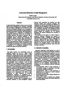
1. Introduction As telecommunications networks developed towards 3G networks, All-IP Networks integrate Circuit Switching and Packet Switching networks [1-2] and thereby provide both real-time services and data services with IP-packets. Topographically, communication networks are mostly connected in networks provided by a group of telecommunication companies. All-IP Networks are composed of Stub Networks and Core Networks [3]. Stub Networks can only provide communications within the same cluster of end users. If end-users need to make long-distance calls, they would probably mark out a number of Core Networks among different operators. Operators have own Core Networks to connect Stub Networks. Core networks hook up the backbone by using domain inter-connection links. When users need services from different telecommunications companies, they send the packets to the backbone via a local Stub Network, and the backbone forwards the packets to a remote Stub Network. So, packets are delivered to the destination host in provision of network services. Refer to Figure 1.
Figure 1.
All-IP Network architecture
1
We break All-IP Networks from hierarchical relations into two subcategories, namely, a backbone and Stub Networks. A backbone is connected by Core Networks. Edge routers of backbones are called Border Gateways (BG). The Border Gateway is an Ingress/Egress router of the backbone. Stub Networks are networks that provide end users’ services directly. They might be public landing mobile networks, e.g., UMTS, GPRS, 802.11, fixed networks or other type of networks. Stub Networks provide services for end users by Network Access Servers (NAS). In this paper, we assume all the surrounding Stub Networks and Core Networks associated with the backbone belong to the same group. The end-to-end QoS controller in QoS coordination layer has the capability of global resource planning. It suggests that an end-to-end QoS controller will plan all resource provisions according to the traffic demands, and all the resource allocation policy will be in accord with the planning. The paper is organized as follows. The next section introduces the QDF and budget-based management. Afterwards, we propose a system architecture for end-to-end QoS provisioning, and finally the simulation study is presented.
2. QDF and Service Classes Mapping Based on the classes of UMTS (Universal Mobile Telecommunication System) [4], Quality parameters are known as delay time, jitter (delay variation) and packet loss. UMTS also separates users’ needs of quality parameters into Conversational, Streaming, Interactive and Background. The four service classes distinguish different quality levels. For example, Conversational classes can tolerance a considerable amount of packet loss, but a little delay; Background bears a totally opposite behavior. In this paper, we present an implementation scheme regarding Quality Deployment applied to communication network management. A Quality Deployment Function (QDF) reflects the value that is reciprocal to the quality level. The smaller value shows the better quality level. Contrarily, the larger value of QDF shows the lower quality level. QDF can be evaluated from delay time, jitter or packet loss. In sequel, we use the QDF as the single index that may be delay time, jitter or packet loss. In general, QDF may be defined in accord to different operators’ need. Taking QDF for the index of the quality level, we need to map the users’ need to QDF.
Figure 2.
Service classes mapping to QDF
2
Consider a case of mapping in UMTS. In Figure 2, the squares denote the service classes, the ellipses for different QDFs. The circles denote the QoS management technologies of the network layer. For example, taking the value of QDF of Conversational class qc, it means the quality level of Conversational class, and the EF class of DiffServ will execute the QoS policy for such a QDF. Based on QDF, we can make an arrangement to balance the resources that satisfy qc for traffic demands of this class.
3. Budget-Based Management In a communication network, an end-to-end path might stride across different operators’ network domain. According to the service level that an end-to-end path carries the path has to give a corresponding quality level guarantee. For example, an end-to-end path which carries Conversational class services has to offer the QDF guarantee, qc. Likewise, an end-to-end path has to offer qs guarantee whenever it carries a Streaming class. In other words, we consider the QDF mapped from service classes as an end-to-end QDF budget. An end-to-end path that does not exceed the QDF budget requirement is said to be competent to carry such service classes. Budget-Based management conceptually disperses QDF budget on the network domains which is traversed by end-to-end paths. Whenever a QDF budget is placed on a network domain, this network domain is responsible for offering a QDF satisfying QoS requirements.
4. System Architecture 4.1 Management System Hierarchy We propose a system architecture with components in “end-to-end Network QoS Coordination Layer” which is responsible for planning an end-to-end QoS.
Layer End-to-end Network QoS Coordination Core-Network Resource Management Core-Network QoS Control (One for each Ingress) DiffServ
Function End-to-end QoS control, end-to-end resource/path planning Allocate resources of a core-network to the QoS Manager of all resource mediators, e.g., Ingress Router in a Core Network or RRM in a 3G Access Network. Implement QoS policy of Core Networks, e.g., admission control, load control, routing and path selection, packet scheduler, etc. Execute the QoS policy designated by the upper layer manager
Table 1.
QoS Management Hierarchy
Components in the upper two layers in Table 1 plan Short paths and Long Paths for potential requests, which are described respectively in Table 2.
3
Planned Path Short Path
Long Path
End-to-end Path
Management Component
Function
BBs and PPAs [5] of Core Networks in Core-Network Resource Management layer
Computed and reserved by PPAs and BBs. A Short Path may cross a Core Network with certain QDF guarantees. Computed by LPPA. A Long Path is composed LPPA* of backbone in end-to-end of Short Paths and may cross a backbone with Network QoS Coordination layer certain QDF guarantees. Provided by global ACA of the entrance Stub Global ACAs of Stub Networks Network. An end-to-end path is composed of in end-to-end Network QoS Long Paths and Stub Network bearer services, Coordination layer and may provide an end-to-end connection with certain QDF guarantees.
Table 2.
Paths of different layers
* LPPA will be defined in Section 4.4.
4.2 Bearer Service Architecture According to classifications in Table 2, an end-to-end Service is composed of bearer services offered by different network domains. A basic long-distance call may traverse through more than two Core Networks. In figure 3, it shows the QDF budget for long-distance calls that pass through network domains.
Figure 3.
Bearer service architecture
4.3 QDF Budget Allocation As discussed in section 3, we have to balance the QDF budget requested by an end-to-end service on network domains, and have to decide an optimal quantity on different network domains. We adopt a two-stage QDF budget allocation, that is, Operator assignment and Off-line Long Path planning respectively. First, the operator considers the abilities of Stub Networks bearing QDF, and defines the rough QDF allocation. For instance, Conversation class has a QDF by class mapping, qc. After the first stage, we send a QDF budget q'c to the backbone. Both entrance and exit Stub Networks have to bear a QDF budget [ (qc-q'c)/2 ] respectively, as shown in Figure 4. The second stage, LPPA sends the QDF budget of backbone to Core Networks. Since a QDF budget is placed on a Core Network, this Core Network has to be responsible for offering QDF less than the total budget. However, there are many different routes that could 4
pass through the backbone. The second stage is an off-line planning procedure. It chooses an optimal set of routes to satisfy every traffic aggregate demand. We define these routes composed of Short Paths and Long Paths.
Figure 4.
First stage budget allocation
4.4 End-to-end QoS Components Long Path Planning Agent, LPPA (Off-line Component) LPPA belongs to end-to-end Network QoS Coordination layer. It is responsible for planning Long Paths. Long Paths are composed of a sequence Short Paths which are planned by PPAs in each Core Networks. The rationale of LPPA is to balance the limited QDF budget and the bandwidth requirement of traffic aggregates. In implementation, the objective of LPPA is to maximize usage of bandwidth as much as possible, while decreasing the penalty made by unsatisfied traffic aggregates or increasing the network capacity. Figure 5 represents the LPPA planned Long Paths corresponding to respective Border Gateways.
Figure 5.
5
LPPA
Long Path table for Border Gateway 1 Destination
Service classes Class 1
… Class 2
Border Gateway 2
(CN1, SP3) (CN5, SP2) (CN1, SP2)(CN4, SP5) (CN5, SP2) …
Border Gateway 3
(CN1, SP1) (CN2, SP6) (CN1, SP9)(CN2, SP7)
…
…
…
…
Table 3.
…
Long Path table (CN: Core Network, SP: Short Path)
Table 3 shows the Long Path table given that Border Gateway 1 is the source Border Gateway. If there is a traffic aggregate of class 1 from Border Gateway 1 to Border Gateway 2. From the second row and second column of Long Path table, this traffic aggregate is arranged to pass through the third Short Path of Core Network 1 and the second Short Path of Core Network 5 sequentially, i.e., (CN1, SP3) (CN5, SP2). Long Paths planned by LPPA in the off-line phase will not be reserved to any traffic aggregate. When there is a traffic demand, Global ACA would send reservation requests to those resources which are under planning. Global Admission Control Agent, Global ACA (Run-time Component) Global ACAs belongs to end-to-end Network QoS Coordination layer. It takes charge of global dynamic admission control. There is no pre-reservation. Before Global ACA determines whether or not it accepts a traffic flow, it has to check if there is any available end-to-end Path.
4.5 Link Characteristics Each link in Core Networks might have several link characteristics (Bandwidth and QDF). Link characteristics depend on network physical features or communication equipments. In general, a link has a worse quality level in a heavy load, but a better quality level in a light load. These characteristics could be formulated as a step function. Operators provide these characteristics to LPPA to make an optimal selection of links under planning.
Figure 6.
Link characteristics
6
By trading-off bandwidth, a link may be tune up to a certain quality level. LPPA has to make an optimal decision of bandwidth according to link characteristics in Core Networks.
5. System Workflow We separate the system workflow into two phases, i.e., an off-line resource planning phase and an end-to-end path reservation phase. An off-line resource planning phase delineates resource provisions. The other phase reserves resources for end-to-end path reservation with real-time on demand in the planning period. Assume there is sufficient time in the phase of off-line resource planning to conduct optimization. In practice, it is impossible in the second phase to wait for real-time resource planning due to the slower response time. Thus, we adopt the method, which is planning before run-time but allocating resources on demand at real- time. To increase the resource utilization of All-IP Networks, we propose a model for the second phase that carries out dynamic resource allocation. Therefore, whenever there is an incoming traffic demand, it would try to allocate resource in real-time according to the off-line planning result.
5.1 Traffic in Aggregate If we want to take each traffic flow into planning, it will cause a serious scaling problem. In this regard, we combine traffic flows with the same source, destination and service class as a single traffic in aggregate. It will alleviate the planning burden. Bandwidth requirement of traffic aggregates is predicted by historical data. Assume the user behavior is similar. We use the seasonal traffic historical patterns to predict the future bandwidth requirements. Border Gateways of the backbone need to collect statistics for the traffic aggregates in historical patterns. Planning Long Paths, we consider a limited QDF budget of traffic aggregates and the bandwidth requirement with load balancing.
5.2 Off-line Resource Planning
Figure 7.
Off-line resource planning
7
The off-line resource planning procedure consists of three steps.
They are
1.
Data Collection: LPPA gets backbone traffic aggregate demand for off-line resource planning. It would acquire planned Short Paths for corresponding time period from PPAs in each Core Network. After gathering data, LPPA begins to build the optimization model for planning Long Paths.
2.
Notify each ACA [6] of the bandwidth allocation: When LPPA completes planning; it notifies the planned bandwidth allocation to each ACA in the backbone for run-time resource reallocation.
3.
Advertise Global ACAs of planned Long Paths: LPPA constructs Long Paths in a table. An example is given in Table 3. LPPA advertises Global ACAs, which is connected to the source Border Gateways, of the Long Path table. Global ACAs would use the table to setup end-to-end paths for QoS demands.
5.3 Real-time On Demand end-to-end Path Reservation The real-time reservation procedure consists of two steps.
They are
1.
End-to-end resource check: Whenever a traffic demand comes, Global ACA maps the service class to QDF first. Then, it checks whether or not the local Stub Network bearer service for this service class is still sufficient. If it is not sufficient, Global ACA will reject this traffic demand. Otherwise, Global ACA will proceed at the next step.
2.
Dynamic end-to-end Path setup: At first, Global ACA would check whether or not the remote Stub Network bearer service for this service class is still sufficient. If it is not sufficient, Global ACA will reject this traffic demand. Otherwise, Global ACA will look up the Long Path table for this service class, and request the Short Paths in order to setup an end-to-end path. Refer to Figure 8.
Figure 8.
Real-time reservation
6. LPPA Optimization Model 6.1 An optimization model Minimize Penalty made by unsatisfied traffic aggregates Subject to Fixed resource (Limited Short Path bandwidth) Traffic aggregate QDF budget must be satisfied
8
Allocate resource to traffic aggregates Trading off QDF with bandwidth in each Short Path
6.2 Experiments We set up an experimental model which constructs a network topology of twenty-four nodes. Ten of them are defined as Border Gateways. The bandwidth of each link is in range of 1200-2400 Mbps, and has different QDF guarantees. We conduct the LPPA optimization with ILOG [7]. Figure 9 shows the planned bandwidth of different classes. Solution A is an optimal solution and the others are feasible solutions. Given each class has different priorities, the premium classes will be considered first.
Figure 9. Planned bandwidth classes Figure 10 shows the network utilization of each solution in six testing cases. Each testing case has the same amount of traffic demands, but we scatter the demand all over Border Gateways to get a balanced bandwidth requirement. It shows the optimal solution can utilize bandwidth usage up to about 70% in average.
Figure 10. Network Utilization
9
7. Conclusion We focus on the differentiated service QoS model and present a possible approach to maximize the resource usage efficiency. The proposed system architecture coping with end-to-end QoS by budget-based management are designed for long-term network resource provision, rather than for setting up individual network connections. We explore the design options implied by the architecture, including Quality Deployment Function, and LPPA Optimization Model. To make end-to-end QoS guarantees more efficiency, concerning parameters of various traffic patterns, a model of forecasting link characteristics is one of future study that enhances this approach.
References [1]
3rd Generation Partnership Project; " Architecture for an All IP network"; 3G TR 23.922 version 1.0.0
[2]
Ivano Guardini, Paolo D’Urso, and Paolo Fasano, CSELT, "The Role of Internet Technology in Future Mobile Data Systems", IEEE Communications Magazine• November 2000
[3]
Tetsuya Takine, Kyoto University Yuji Oie, Kyushu Institute of Technology Katsuyoshi Iida and Kenji Kawahara, Kyushu Institute of Technology, “Performance Evaluation of the Architecture for end-to-end Quality-of-Service Provisioning”, IEEE Communications Magazine•April 2000
[4]
3rd Generation Partnership Project; " QoS Concept and Architecture (Release 5)"; 3GPP TS 23.107 V5.3.0 (2002-01)
[5]
Yao-Nan Lien, Tsung-Hsung Li, " Path planning in DiffServ Domain under budget-based control", Master Thesis, June 2003.
[6]
Yao-Nan Lien, Ming-Chin Chen, " Budget-Based Admission Control on DiffServ Core Network", Master Thesis, June 2003.
[7]
ILOG Software: product OPL Studio, library opl.lib, version 3.5.1, date Nov 12 2001.
10