ENERGY-AWARE AND BANDWIDTH-EFFICIENT MOBILITY ARCHITECTURE FOR 6LoWPAN Gargi Bag, Muhammad Taqi Raza H. M, Hamid Mukhtar, Ali Hammad Akbar, S.M. Saif Shams, Ki-Hyung Kim, Seung-wha Yoo and †Donghwa Kim Department of Information and Communication Engineering Ajou University, South Korea {gargi, taqi, hamid, ahakbar, kkim86, swyoo}@ajou.ac.kr † Agency for Defense Development, Korea †
[email protected]
ABSTRACT because of their inherent properties, provide better coverage, fault tolerance and robust behavior.
This paper proposes an energy aware and bandwidth efficient mobility support architecture which handles mobility of 6LoWPAN devices, such that the communication between it and its corresponding nodes remain undisrupted. As the 6LoWPAN devices are energy and resource constrained enabling mobility in these devices with the help of conventional Host Based protocols like MIPv6 is not suitable. Moreover, it may be possible in many scenarios that the Mobile Node (MN) moves far from the Gateway (GW), while communicating with it. In this case the MN has to increase its transmission power, which may adversely affect its life time. In the proposed architecture static random deployed 6LoWPAN devices (SN) with same characteristics as the MNs, facilitate mobility such that the IP connectivity of the MN is maintained with minimum signaling at MN’s end. Thus this paper describes the link layer specific mechanisms needed between the SN and the MN to help it perform multi-hop communication with the GW. Moreover, it is designed keeping in mind the energy and resource constraint nature of SNs themselves. The signaling overhead for the SNs is determined through analytical modeling. I
As the technology is maturing with time, many intriguing applications are surfacing that require a certain degree of mobility among the PAN devices. However providing IP connectivity to mobile 6LoWPAN devices means that the devices needs to empowered with traditional mobility related IP protocols like MIPv6, HMIPv6 [4, 5] etc. However, it is not feasible for the MN to be associated with host based mobility protocols as they require most of the signaling on MN’s end. Network based mobility protocol such as PMIPv6 [12] is a suitable candidate to enable mobility in 6LoWPAN devices. In PMIPv6, the gateway handles all the mobility related signaling on behalf of the MN. However the protocol assumes that the device communicates with the gateway in a single hop communication, which can severely affect the lifetime of the MNs. This paper proposes an energy and bandwidth efficient mobility architecture which supports mobility of 6LoWPAN devices in diverse types of environments. The mobility architecture caters for the energy constraint nature of the MNs and thus enables multi-hop communication between the Gateway (GW) and MNs via some low priced static 6LoWPAN nodes. Moreover, the MNs do not require any changes in the software stack and is exempted from too much mobility related signaling. However, if a static 6LoWPAN device has to route IP packets to MN, it will be exhausted of its energy in no time. Instead we propose to utilize the reserved adaptation layer dispatch values of 6LoWPAN to help SNs identify and route packets related to MNs. Thus in the proposed architecture the adaptation layer packets are transmitted over the multi-hop links instead of IP packets. This reduces the number of bits transmitted by the SNs. Also the propose architecture is designed keeping in mind that the SNs themselves are resource constrained and thus need to periodically switch to sleep state. The performance evaluation compares the amount of signaling required by MN in the proposed mobility architecture with HMIPv6. The signaling overhead for the SNs is determined through analytical modeling. The overhead is determined against parameters like speed and packet arrival rate of the MN. Also, as the MN does not have to configure its link layer and IP layer address, every time it moves the handoff latency and packet loss is minimized in the proposed mobility architecture.
INTRODUCTION
IEEE standard 802.15.4 [1] has emerged as a strong technology for WSNs to morph Personal Area Networks (PANs) into Low power Personal Area Networks (LoWPANs). LoWPANs are characterized by low data rates, low power consumption, low cost, autonomous operations and flexible topologies. The introduction of LoWPANs can be considered as the beginning of a new generation of applications. The integration of various simple devices which are able to be connected to the networks makes ubiquitous computing closer than ever to us. In order to fully realize a pervasive or ubiquitous environment, LoWPANs must be connected to the Internet Protocol (IP)-based networks. This integration would make the resource sharing possible within both networks, maximizing the utilization of available resources. Internet Engineering Task Force (IETF) is standardizing the transmission of IPv6 over LoWPANs through a working group known as 6LoWPAN [2]. 6LoWPANs are envisioned to play a major role in the future pervasive paradigm. The emerging range of 6LoWPAN applications includes consumer appliances, home automation, monitoring and control in industrial environments, military and environmental monitoring and sensing. These networks,
The remainder of the paper is organized as follows. Section II, describes the related work followed by the 6LowPAN
978-1-4244-2677-5/08/$25.00 ©2008 IEEE
1 of 7
new entity called mobile anchor point (MAP) which acts as a local home agent of the MNs [5]. FMIPv6 is another enhancement of MIPv6, which aims to reduce handoff delays for mobile connections. However, the host based mobility protocol involves most of the signaling on the MN’s end which cannot be realistic for 6loWPAN nodes. Also the protocols expect the MN is expected to indulge into IP layer signaling including all signaling required to configure an IP address on a new link. Moreover, these protocols demands a complex host stack, which is not feasible for 6LoWPAN considering their inherent constraints.
mobility requirements in section III. Section IV defines the system model and assumptions. The next section, section V describes the proposed architecture. Section VI discusses the communication scenarios followed by mobility and the network model in section VII. Performance evaluation follows next in section VIII and finally section IX concludes the paper. II
RELATED WORK
Mobility of 6LoWPAN can give rise to new and exciting applications. Especially in the case of M-Health, 6LoWPAN sensors worn by patient can provide better monitoring scope since it is connected to the internet. In [15], authors have stressed that the most relevant technology for M-Health is technologies similar to 6LoWPAN like Bluetooth and Zigbee in terms of low cost, low-size and low power radio technology as these are the characteristics of a typical wireless sensor devices/networks.
Network based localized mobility like PMIPv6 [12], also proposed by IETF, is where the network side performs the mobility-related signaling on behalf of the MN. NETLMM introduces several new entities like Localized Mobility Anchors (LMA), Mobile Access Gateway (MAG) etc. These entities together detects the MN’s movement, sets up the data path to enable the MN to use its home address from communication from the access link, emulates MN’s home link on the access link. The interface between the MN and MAG is defined at the IP layer and is applied to single hop. However single hop communication is not suitable for 6LoWPAN devices. In contrast this paper describes the link layer specific mechanisms needed between the SN and the MN to help it perform multi-hop communication with the GW.
In [14], authors have proposed a design of micro mobility support for a sensor node roaming across several Access Points (AP) of a Bluetooth sensor networks. In it authors proposed to assign IP address to an AP and a sensor node to identify a MN instead of identifying it with channel number. Also they designed a middleware to carry IP packets over Bluetooth. However they assume that the sensor node is capable to perform single hop communication even if the MN is not that close to the AP. Moreover the MNs are expected to incorporate a middleware layer changes in their stack in order to support their mobility.
III
MOBILITY REQUIREMENTS IN 6LOWPAN
Mobile wireless sensor without any IP ubiquity can also support numerous applications. Mobility of sensor nodes can ensure large area coverage along with the presence of more devices at the point of interest [11]. Furthermore, it can help in load balancing and filtering of local data at the node before transmission. In [7] authors proposed a model to support user mobility in WSNs. However, it does not support communication between two mobile users or nodes as they move within the sensor field
One of the possible scenarios, which require mobile 6LoWPAN devices, is when they are used for monitoring purposes like monitoring of heart beat, temperature and pulse rate of patients moving within the hospital building. In this case, every room will have SNs deployed, which will help the MN to communicate with the GW. Mobility requirements in 6LoWPAN include [11]:
In [13] authors proposed an architecture of multi-radio enabled mobile wireless sensor network (MEMOSEN). According to them the mobile terminals with multiple radio transceivers can act as either a sensor or a sink node. However as most of the sensor nodes and 6LoWPAN nodes is still short range and does not support such technology.
3.
1. 2.
Providing fast handover detection. The mobile devices should be addressable by any correspondent irrespective of its whereabouts. Also the signaling is also required to be minimized considering the resource constraint characteristic of the LoWPAN devices IV
In [3] authors have proposed an interoperable architecture between NEMO and 6LoWPAN to support network mobility. They have suggested an extended routing scheme for mobile routers to support mobility in 6LoWPAN sensor nodes. However the architecture does not cater for individual node mobility.
SYSTEM MODEL AND ASSUMPTIONS
Our proposed mobility architecture is based on the following network assumptions: 1. 2.
The host based mobility protocols like MIPv6, FMIPv6 and HMIPv6 was proposed by Internet Engineering Task Force [2]. In MIPv6, when a node moves from one network to the other, the node itself updates its current care of address to its Home Agent. Also it performs Return Routability Test as security measures. HMIPv6 adds another level on MIPv6 and separates global mobility from local mobility. It introduces a
3. 4.
2 of 7
A MN is an active device which is moving between multiple GWs. The current velocity of the MN is strongly dependent on its previous velocity. The GWs are interconnected with each other through wireless or wired links. The area under the interconnected GWs is referred to as a domain.
5.
The SNs in the proposed architecture are densely deployed to an extent that their transmission and sensing ranges overlap. 6. IEEE 802.15.4 networks provide two types of addresses, IEEE EUI64-bit extended address and 16-bit short addresses. 7. The SNs are assigned with IPv6 address and with 16 bit short address. These nodes are associated with one of the GWs. 8. The IP address of the MN and 16-bit short address or MN ID remains the same irrespective of its location in the domain. 9. Each 6lowPAN device has the same transmission signal strength and receiver sensitivity. 10. Each SN measures the distance between itself and the target based on the received signal strength (RSSI) [6]. 11. Each SN is equipped with a radio-triggered hardware component that activates sensors from/to the sleep state, by sending a special wake up radio signal [8]. 12. The interoperability between IPv6 domain and the IEEE802.15.4 device is handled by the adaption layer [9]. V
4.
Static nodes: The static nodes in the proposed architecture are deployed under different GWs to do the following tasks. 1.
Predicting the future location of the MN: As the SNs are themselves resource constrained, they spent most of their time in sleep state. When a MN associates with a SN, the associated SN keeps a track of MN’s movement. It then activates the next SN in sleep state with which the MN can associate depending on the direction of its movement.
2.
Indicating to the MN that it has moved: When the old SN activates the new SN, it transmits Hello_packets at certain intervals. The Hello_packet contains SN’s short address which enables the MN to determine that it has moved.
3.
Sending Location Update to the GW: When the old GW activates the new SN, the new SN sends a LU to the GW. This helps to route data packets to the MN.
4.
Routing of MN’s data packets: The SN also route MN’s data packets. Any energy efficient routing schemes can be used to route data packets [16, 17].
5.
Forwarding the MN’s packet to the new location: The old SN keeps forwarding the MN’s packet until the LU message from the new SN reaches the GW.
MOBILITY SUPPORT ARCHITECTURE
Any proposed mobility support architecture should be such that only network side changes are required to support 6LoWPAN device mobility. The device themselves does not have to perform any software upgrade. V.I Operational Architecture In the proposed architecture the GW, SNs and the MNs have the following roles.
Mobile node: When it receives an indication that it has moved, in form a hello_message it sends an association_request message to the new SN.
Gateway: In the proposed architecture it is assigned additional functionalities like sending Binding update and storing bindings of the MNs in order to provide mobility support to the 6loWPAN nodes. The detail functionalities of GW are given below. 1. Protocol Translation: Since in the proposed architecture the static 6LoWPAN nodes are helping in routing data packets to or from the MN, it is more appropriate not to transmit IP packets over multi-hop link. Instead IEEE802.15.4 frames encapsulated in adaptation layer header can be transported over wireless link. The GW thus fragments IP packets before sending it to the MN and assembles the adaptation layer packets into an IP packet before sending it to the correspondent node (CN) outside the domain. 2. Address Translation: This architecture proposes to use 16bit short address for the entire static and MN. Thus the GW has to translate the 16 bit short address to an IP address. 3.
Binding update to other GWs: When a MN enters the domain for the first time; the GW has to send a Binding Update (BU) to the MN’s home agent and also to the CNs if required. Also if it is connected to multiple GWs, the current gateway has to inform the other GWs about the MN’s new location.
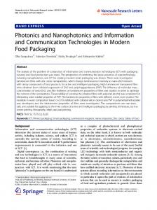
V.II MN entering the Domain Figure 1 shows a domain with different GWs which are interconnected and the MN is moving within the domain. The SNs at the boundary of the domain are in a quasi sleep state. Thus, their sensor is turned on whereas their transceiver and processor is switched off. When the SN senses a MN, it wakes up from quasi sleep state to active state. In active state it periodically transmits a hello_packet. When a MN enters the domain for the first time it scans the entire frequency channels to receive a hello_packets from a SN. Once it receives a hello_packet, it sends a join_request packet to the SN from which it received the hello_packets. The join_request message contains MN’s Home address, and its entire CN’s IP address. The SN then forwards the join_request packet to the GW. Upon receiving the join_request message, the GW assigns a unique ID (16 bits) and a care of address (IP) to the MN. Also it maps the CN’s IP addresses into unique short address in order to save the communication cost. It then sends the MN’s ID and its CN’s mappings to the SN in form of a join_confirm message. The SN then informs MN of its newly assigned ID along with the mappings of the IP addresses and short addresses of its CNs. Also GW stores mapping of the MN’s ID, it’s HoA and its current associated SN’s short address along with its CN’s short address and their
Storing Bindings of the MN: As seen from figure 2 the GWs keep a binding table which maps the MN’s ID, its current location, Home address, and CN’s IP address. 3 of 7
awakes the next SN from sleep sate (represented as II in Figure 3) for the handoff. Also it sends a new_node message to it, which contains MN’s ID.
IP address. It then sends a BU to the Home Agent, CNs of the MN along with the other GWs of the domain.
Figure 2: Next node activation Process
When the new node receives the new_node message it transmits a hello_packet at some intervals. It also sends a LU to the GW. Upon receiving the hello_packet, the MN sends an association_request packet to the new SN. When the new SN receives the association_request, it again sends a new_node message to the old SN. From the time the old SN receives the new_node message, it starts to forward the MN’s packets to the new location till the LU reaches GW. After the LU reaches the GW, it forwards the MN’s packets to the new location. As soon as the MN’s packets stop arriving at the old SN, the SN switches to a sleep mode after a specified interval of time. The handover support mechanism is support in figure 3.
Figure 1: Network model
V.III Handoff Support Once the associated SN (with which a MN is currently associated) observes that their link quality has degraded beyond a certain threshold, it assumes that the MN is moving. Hence the current SN needs to activate the next appropriate sensor node for the handoff process. In order to activate the next appropriate SN, the associated SN must know the direction where the MN is moving. The direction can only be found through localization procedure, where a series of MN’s locations depict its course of movement, i.e. tracking. There are various methods to obtain mobile node location like, trilateration/triangulation method, AOA (angle of arrival) and TOA / TDOA (time {difference} of arrival) method, signal strength indicator etc.
OSN
MN
NSN
GW
Radio_trigger New_node Hello_pac
LU
Asoc_req
To enable the SN to determine the direction of movement, we propose to use AoA method. AOA is defined as the angle between the propagation direction of an incident wave and some reference direction, which is known as orientation. Orientation, defined as a fixed direction against which the AOAs are measured, is represented in degrees in a clockwise direction from the North. When the orientation is 0o or pointing to the North the AOA is absolute; otherwise relative. We assume that each sensor node is equipped with an antenna array in order to obtain AOA measurements.
New_node data pkts data pkts
data pkts
data pkts
OSN: Old static node NSN: New static node GW: Gateway MN: Mobile Node
Figure 3: Handoff Support
In order to differentiate different kinds of mobility messages exchanged between nodes we propose to utilize the adaptation layer’s reserved dispatch values [9]. Every adaptation layer packets begins with a dispatch value which identifies what kind of header is following. The dispatch value is a 8 bit value that indicates what kind of packet is it. For example a dispatch value 01 000001 indicates that the following header is an uncompressed IPv6 header.
Figure 2 describes the next node activation process in our approach. As shown in Figure 5, ‘the star’ shows MN position at time-stamps TS1, TS2 and TS3 respectively. The associated SN measures the AoA from the signal that it receives from the MN. Moreover the associated SN also estimates the distance between the MN and itself, using received signal strength of the packets.
Thus in this architecture we propose to identify mobility related packets with the use of specific dispatch values. The dispatch values of some of messages are shown in table 1 below.
As shown in Figure 3, α1, d1 ; α2, d2 ; α3, d3 be the angles (in degrees) and the distances between the associated node and the MN, at time-stamps TS1, TS2 and TS3 respectively. Based on angle and distance information, the sensor node can obtain MN’S location coordinates. At the time-stamp TS3, the SN 4 of 7
Table 1: Dispatch values Dispatch value 01 000011 01 000111 01 001111 01 111110 01 011011 01 101111
VI
crosses the square, it associates with another SN from which it receives a hello_packet.
message Join_request Association_req Hello_packet New_node Location_update Data packets for MN
For evaluation purposes we assume the following: 1.
A domain is composed of N equal squares that are equal in size and form a contiguous area.
2.
The MNs are moving with an average speed of v and direction of their movement is between 0 to 2π.
For analysis of signaling cost during the MN’s average domain residence time we assume that it moves out of the domain within K finite movement. From [10], it can be seen that µ(k) (average number of SN, a MN associates with) is rarely sensitive to change of K unless K is much smaller than N. Thus we assume K equal to N.
COMMUNICATION SCENARIOS
Figure 1 show two MNs associated with two different gateways communicating with each other. When the MN has to send data packet to another MN it transmits the packet with a specific dispatch value. The dispatch value indicates that it is a data packet from a MN whose recipient is the GW. When a SN receives the packet, it checks whether the MN is associated with it or not. If not, then it discards the packet otherwise it forwards the packet to the node closer to the GW. The message format is shown below.
The signaling cost in the proposed solution can be broken down to: 1. The cost incurred in sending LU messages to the gateway and the cost of sending new_node messages, every time a MN associates with a new SN. 2. The cost incurred in tunneling data packets from the gateway to the SNs of the destination MN. The default parameter value is given in table 3.
Figure 4: Data packet from MN to GW
When the data packet reaches the GW, it checks whether the destination MN is associated with it one of its SNs or not. If it is associated then creates a bidirectional tunnel between itself and the SN and transfers the packet. If the destination MN is associated with some other gateway, then GW tunnels the packet to destination GW, which then forwards the MN. If the source and the destination are located near each other and if mobility is low for both source and destination MN, then GW can update the SN of the source MN with the short address of the destination MN’s SN. The Source SN can then tunnel the packet to the destination SN. In case, any one of the MN moves, the MN’s associated SN informs the SN about it. When the MN has to send a data packet to a CN which is not in the same domain, it uses its short address assigned by the GW as its destination address. The GW then replaces it with its IP address and sends it to the CN outside the domain. When a packet comes from outside, the reverse process occurs.
Figure 5: Network Model
In table 2 the signaling bandwidth in bits for location update is the size of the dispatch header (8 bits) plus the 16 bit address of the SN plus 16 bit MN ID. Table 2: Default parameters
VII MOBILITY AND NETWORK MODEL
Name N R λ b t L DA v S
We use the fluid flow mobility model. In that case the binding update pattern of a MN can be modeled using a continuoustime Markov Chain. The states in the Markov chain identify the number of SNs with which the MN associates in a given domain. Transition b2,0 indicates that a MN associates with two SNs and then move out of the domain. In figure 5 shows a possible route taken by the MN inside a domain. In this figure the squares identifies the association region of a SN. Within this square, the link quality between the MN and the SN is above a threshold. When the MN
Description Domain size Range of IEEE 802.15.4 devices (radius) Packet arrival rate Signaling bandwidth (LU messages) in one hop Signaling bandwidth (tunneling cost) in one hop Average number of link hops to GW Domain Area Average speed Signaling bandwidth (new_node) in one hop
Value 12 15m 0.001 pkt/sec 40 bits 16 bits 3 105m*45m 0.1m/s 56 bits
Similarly extra 16 bits are required in tunneling the packet due to the MN in the proposed architecture. 5 of 7
VIII.II Location update cost versus speed Figure 5 shows a possible path followed by a MN as it enters a domain. Figure 6 shows the LU cost (bits) incurred due to the MN’s movement in the same path with different speed. It shows that as speed increases LU cost does not change. This is due to the fact that even if the speed of the MN increases, it associates with same number of SN which comes in its path and thus sends same number of binding update messages.
1. Location Update cost μ
1
μ
1
2
1
2 3
Signalling overhead(bits)
Equation 1 gives the average LU cost (bits) incurred due to a MN’s K movements inside the domain. It includes both the LU cost to the GW and cost to send new_node message, associated with MN’s K number of movements. Also π0 is the equilibrium probability of the state 0 which represents the probability that the MN stays outside a given domain. In this case we assume that the probability of MN staying outside the domain is same as staying inside. 2. Tunneling cost μ
4 (5)
In the above equation, λ is the average packet arrival rate to a SN when it is connected to a parent node. The time for which a MN remains connected to a SN can be referred to as Tas and can be given as [10]: √
3000 2500 2000 1500 1000 500 0
HMIPv6
0
2
4
6
8
10
v (m/s)
6
Figure 6: Location updates signaling versus speed
Where, A is the area of the square shown in figure 7. Figure 6 also shows that in HMIPv6 the location update cost lessens with increase of speed as the amount of binding refresh reduces. Moreover it can be seen that the signaling overhead in bits of the proposed architecture is significantly less as compared with HMIPv6. This is due to use of adaptation layer packets for sending LU, instead of using IP as in the case of HMIPv6.
VIII PERFORMANCE EVALUATION This section provides a comparison between HMIPv6 and proposed architecture in terms of number of signaling needed at the MN’s end. Also it evaluates the signaling overhead in bits with respect to speed and packet arrival rate. VIII.I Signaling comparison between Proposed Architecture and HMIPv6 In the table 3 it can be clearly seen the MN is exempted from most of the mobility related functionalities like sending Bus to home agent, CN and local home agent. The local home agent in this case is the GW. Also the MN does not have to configure its link layer and IP layer from the advertised prefix. The network does all that for the MN. Moreover since the link layer and the IP layer address is not changing every time the MN moves, the handover latency is small compared to other mobility protocols like MIPv6 and HMIPv6.
VIII.III Tunneling cost Vs Packet arrival rate Packets are tunneled from the gateway to the destination MN’s SN. According to equation 4, the tunneling cost increases linearly as the number of packets that arrives for a MN in a unit time, increases. However from figure 7 it can be seen that tunneling cost of the proposed architecture is still less compared to HMIPv6 as in HMIPv6 additional signaling bandwidth consumption generated tunneling per packet is equal to the size of an IPv6 header.
Functionalities required by MN Sending BU to HoA and CN Sending Local BU to MAP/GW Forming LCoA
HMIPv6 Yes
Proposed Architecture No
Yes
No
Yes
No
Signalling overhead (bits)
Table 3: Signaling comparison between proposed architecture and HMIPv6
The proposed mechanism can be evaluated in terms LU cost, tunneling costs with respect to speed of the MN, the no. of hops the packets travel (LU and data packets) and packet arrival rate. Also the network energy consumption is evaluated with respect to speed of the MN.
20 HMIPv6
15
Propsed Protocol
10 5 0 0
0.002 0.004 0.006 0.008 0.01 Packet arrival rate (pkt/sec) Figure 7: Tunneling cost Vs packet arrival rate
6 of 7
0.012
REFERENCES
mWatt
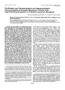
VIII.IV Network energy conssumption Vs speed We have benchmarked the energy model as explained in [18], which measures the network energy consumption over time. We have measured the total network energy consumption by varying the speed of the MN over different network bandwidths. In order to increase the bandwidth the SN need to operate at higher frequency by increasing reception/transmission power. This results in more energy consumption. Moreover as the speed of the MN increases, the SN finds less time in sleep mode; resulting more network energy consumption. The efficacy of our proposed approach can be seen from Figure 8. When the bandwidth of the network is increased upto four times, then the network energy consumption is increased twice only. At the other hand, linear network energy consumption is observed with the increase of MN speed. Because when the MN is moving fast, then handover association with the next SN will occur more frequently. This causes more energy consumption as compared to the slow speed MN, where it keeps association with the SN for a long time period and follows almost same routing path towards the GW. Note that, here we are measuring the overall network energy consumption. Thus frequent handoff and MN association with SN causes consumption of more energy consumption. 500 400 300 200 100 0
[1] [2] [3] [4] [5] [6] [7] [8] [9] [10]
[11] [12] [13] [14]
1.3 Kbps [15]
2.5 Kbps 1 2 3 4 5 6 7 8 9
5.7 Kbps [16]
Speed (m/s)
[17] Figure 8: SNs power consumption with variable MN speed on different network bandwidths
IX
[18]
CONCLUSION
This paper provided a network assisted mobility support scheme for 6LoWPAN nodes which are extremely energy and resource constrained in nature. Through this mobility support architecture, the MNs can communicate with any node without being involved in significant amount of signaling. Neither the MN had to incorporate any major changes in its protocol stack. Moreover since the MN does not have to reconfigure its short address or its IP address every time it moves; hence the handover latency in both second and third layer is greatly reduced. This reduces packet loss as well. Since adaptation layer data packets are transmitted, instead of IP layer directly over multi-hop link, it greatly reduces the bandwidth consumption as compared to transmitting IP directly to the MNs (as seen in the performance evaluation section). X
ACKNOWLEDGEMENT
This research was funded in part by Dual Use Technology Program and ADD Korea and was supported in part by the IT R&D program of MKE/IITA (ITAA1100080200990001000100100). 7 of 7
802.15.4-2003, IEEE Standard., "Wireless medium access control and physical layer specifications for low-rate wireless personal area networks”, May 2003. Internet Engineering Task Force http://www.ietf.org/ Jin Ho Kim et al,” A Routing Scheme for Supporting Network Mobility of Sensor Network Based on 6LoWPAN” Springer 2007. Debashis Saha et al,” Mobility Support in IP: A survey of Related Protocols”, IEEE Network, December 2004. H.Sollman et al,”Hierarchical MIPv6 Mobility Management”, RFC 4140, august 2005. L. Zhang, Q. Cheng, Y. Wang, and S. Zeadally, "A Novel Distributed Sensor Positioning System Using the Dual of Target Tracking,", IEEE Transactions on Computers, Vol. 57, No. 2, pp. 246-260, February 2008. Sang-Sik Kim et al, “Mobility Support for Users in Wireless Sensor Networks”, Eighth International Symposium on Autonomous Decentralized Systems, 2007. Lin Gu and John A. Stankovic, “Radio-Triggered Wake-Up for Wireless Sensor Networks”, 10th IEEE Real-Time and Embedded Technology and Applications Symposium, 2004. N.Kushalnagar., Montenegro, G., Hui, J., and D. Culler, "6LoWPAN: Transmission of IPv6 Packets over IEEE 802.15.4 Networks", RFC 4944, September 2007. Ki-Sik Kong, MoonBae Song, KwangJin Park and Chong-Sun Hwang, “A Comparative analysis on the signaling load of the Mobile IPv6 and Hierarchical Mobile IPv6: Analytical Approach” IEICE TRANS, January 2006. M-K. Shin, T. Camilo, J. Silva and D. Kaspar,”6LoWPAN mobility Requirements”2007. S. Gundavevelli, Devrapalli, K. Chowdhury and B. Patil, “Proxy MIPv6”, May 2008. Canfeng Chen, Jian Ma, “Mobile Enabled Large Scale Wireless Sensor” ICACT 2006. Xiao NI, Weiren SHI, Xiao NI, and Song Zheng,” Design of micro mobility support in Bluetooth sensor networks”, IEEE International Conference on Industrial Informatics, 2006. Robert Istepanian, Emil Jovanov, Y. T. Zhang, ‘‘Guest editorial introduction to the special session on M-Health: Beyond Seamless Mobility and Global Wireless Health-care connectivity”. IEEE Transactions on Information Technology in Biomedicine, Vol. 8, No.4, December 2004. Haifeng Hu, Zhen Yang,”Cooperative Opportunistic Routing protocol for Wireless Sensor Networks”, IEEE, 2007. Hongju Cheng, Xiaohua Jia, “An Energy Efficient Routing Algorithm for Wireless Sensor Networks”, IEEE, 2005. O. Landsiedel, et al., “Accurate prediction of power consumption in sensor networks”, Workshop on Embedded Networked Sensors, 2005