suitable for the digital interface to a Liquid Crystal Dis- play (LCD). In particular, we focus on interfaces that are compliant to the Digital Visual Interface (DVI) ...
Energy-Efficient Bus Encoding for LCD Displays Alberto Bocca∗ ∗
Sabino Salerno∗
Enrico Macii∗ †
Politecnico di Torino Torino, ITALY
ABSTRACT This paper presents a low-power bus encoding technique suitable for the digital interface to a Liquid Crystal Display (LCD). In particular, we focus on interfaces that are compliant to the Digital Visual Interface (DVI) standard, in which the three color channels are serially transmitted to achieve high bandwidth. The proposed technique exploits the well-know inter-pixel correlation that exists in typical images by serially transmitting an encoded representation of the difference between adjacent pixels. The encoding is based on the principle of clustering the 1’s in the code towards either ends of the pixel data, in such a way that serial transmission of a code yields at most 1 transition per pixel. The application of the encoding to a series of standard images resulted in energy savings of around 60% on average, with respect to a plain transmission of 8-bit pixel data. Categories and Subject Descriptors: B.4.2: Input/Output and Data Communications: I/O Devices General Terms: Algorithm, Experimentation. Keywords: LCD Displays, Digital Display Interfaces, LowPower Bus Encoding.
1.
INTRODUCTION
In spite of the high computational power of the processor cores and the huge amount of DRAM memory, the Liquid Crystal Display (LCD) system is still one of the most energydemanding components of modern multimedia devices. Although most of the power is consumed by the LCD panel (e.g., it can easily exceed the 1 Watt mark [10]), the LCD takas a significant fraction of the total power budget (typically around 10%). This is because this bus is usually implemented through a flat cable whose unit capacitance per line is orders of magnitude larger than that of on-chip buses. This power demand cannot be easily tackled as for other resource, for instance, through some form of power management. The LCD is intrinsically a non-power-manageable
Massimo Poncino†
Universita` di Verona Verona, ITALY
resource; it must be continuously refreshed, and shutting it down cannot be done without significant penalty in performance and image quality. In this scenario, design techniques that facilitate the reduction of the switching activity of digital LCD buses assume higher importance than in the cases, widely addressed by the literature on low-power bus encoding, of parallel, memoryto-processor buses (see [1] for a survey). Of particular interest, in the context of LCD interfaces are encoding solutions targeting serial communication channels. In fact, most LCD interfaces use serial connection to minimize the electrical effects occurring during the transmission of data on a flat cable at frequencies in the range required by typical LCD displays (in the order of few hundred of MHz). Cheng and Pedram [2] have recently proposed an encoding schemes, named Chromatic Encoding, which reduces the switching activity on each color channel based on the exploitation of the concept of tonal locality, that is, on the fact that pixels that are adjacent in an image tend to have large similarity in their RGB color decomposition. In this paper, we improve over the work of [2], by proposing an encoding solution which exploits inter-pixel correlation in a different way. In particular, we specifically target the encoding function to the serial nature of the transmission; the basic idea of the method is to minimize intra-word transitions by clustering the 1’s in the encoded values towards one end of the word. The proposed method provides comparable savings (about 60% on average), yet with a much simpler encoder structure, and without any kind of approximation (such as overflow or non-representable values).
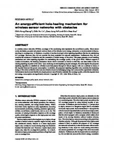
2. BACKGROUND AND PREVIOUS WORK Figure 1 shows the organization of a typical digital LCD subsystem. In particular, the graphic controller, which contains the frame buffer transmits to the LCD controller, through a digital interface, the pixel data. Unlike its analog counterpart (for which VGA and successors are an universal standard), the digital interface the graphics controller and the LCD has long been a matter of many controversies among LCD producers and PC makers; as a matter of fact, no official standard has emerged yet, and no solution has even managed to achieve widespread acceptance. Among the various proposals for a digital LCD interface (Plug and Display [4], Digital Flat Panel (DFP) [5], OpenLDI [6]) DVI (Digital Visual Interface) [7] has lately appeared as the solution that satisfies most of the contrasting requirements. It has been proposed by Digital Display
Permission to make digital or hard copies of all or part of this work for personal or classroom use is granted without fee provided that copies are not made or distributed for profit or commercial advantage and that copies bear this notice and the full citation on the first page. To copy otherwise, to republish, to post on servers or to redistribute to lists, requires prior specific permission and/or a fee. GLSVLSI’04, April 26–28, 2004, Boston, Massachusetts, USA. Copyright 2004 ACM 1-58113-853-9/04/0004 ...$5.00.
240
3. LOW-POWER ENCODING
�������� � �� �
3.1 Motivation ����� ������
������� ��� ��
����
�� � �
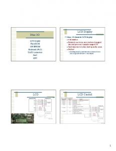
The motivation behind the proposed encoding comes from a widely used property of digital images, that is, the high correlation existing between adjacent pixels. Figure 2 shows the distribution of the distance between adjacent pixels for the three (R,G,B) channels; the various curves are averaged over a sample of ten images. The distribution is roughly Gaussian, with average value approximately 0 (i.e., identical adjacent pixels) and very small variance (0.0031) for the depicted curves.
���� ����
� �
��
���
������ � ���
��� ���
Figure 1: Organization of a Typical LCD System.
���
� � �
���
Working Group (DDWG), driven by Intel and includes companies such as HP, Fujitsu, IBM and NEC. Like its competitors, DVI is based on a specific signaling technology called TMDS (Transition-Minimized Differential Signaling) to send data. This interface is implemented using an encoder and serializer to format the digital RGB data, which is then serially transmitted on three twisted pairs, with an additional twisted pair for the clock signal. Each 8bit pixel data is encoded and serialized into a 10-bit value. TMDS achieves low transition counts by using transition encoding, where transitions are encoded rather than values. The precise encoding depends on the value of the first redundancy bit. When 1, transitions are encoded with Boolean XOR (i.e., 1 = transition, 0 = no transition); conversely, when 0, Boolean XNOR is used. The second redundancy bit is used to selectively invert (i.e., complement) the word to be transmitted so as to achieve DC balancing. The most appealing feature of TMDS is that the clock is only used as a frequency reference, and not to latch data, which provides excellent clock skew insensitivity. In spite of its name, TMDS has not been devised with energy consumption in mind. The minimization of transitions has been mostly sought to avoid excessive electromagnetic interference (EMI) levels on the cable. As a matter of fact, energy efficiency techniques for LCD systems have been limited so far to the design individual component for the display systems [8, 9] or for specific control mechanism inside the LCD controller [10, 11]. The only approach that has dealt with the issue of energy efficiency during the transmission of data on the digital LCD interface is the one proposed by Cheng and Pedram in [2]. In their work, they use the same DVI-compliant interface (the 10bit serial link) to transmit properly encoded pixel data by exploiting the correlation existing between adjacent pixels. The encoding, called chromatic encoding, provides significant savings, but it presents several corner cases in which pixels cannot be encoded (overflow conditions, or situations in which the encoding must switch to plain TMDS). The encoding proposed in this work is similar in scope to that of [2], in that it assumes the availability of a DVIcompliant physical connection. With respect to that solution, however, we provide comparable energy savings, with no approximation or corner cases, and with a simpler encoder/decoder implementations.
��� ��� ��� ��� ��� ��
�� � �� � �� � �� � �� � �� � �� � �� � �� � �� � �� � �� �� �� �� �� � � � � � �� �� �� �� �� �� �� �� �� �� ��
�� � � ����������� � ��
Figure 2: Distribution of Pixel Difference. This correlation is called tonal locality in [2]. Such spatial correlation of images is exploited in most image compression algorithms, which rely on a differential representation, where differences are stored rather than full information.
3.2 Differential Bar-Encoding Our encoding exploits inter-pixel correlation in the simplest possible way, that is, by transmitting pixel differences rather than their actual values. However, this differential encoding does not guarantee by itself any reduction of the number of transitions on the channels. To achieve that, a suitable encoding of the difference is required. In our specific context, the vast literature on bus encoding for reduced switching activity is not of help, since all these methods target parallel buses. In the case of a serial bus, as for our links, a different solution must be devised. The serial requirement, in fact, rules out many of the principles used for reducing transitions on parallel buses, namely, spatial redundancy and code mappings. In our case we can only play with (i) the temporal redundancy, and (ii) the temporal sequence of the transmitted bits. The former is defined by the constraints of using TMDS links, that is, we are allowed two redundancy bits per symbol (for a total of 10 bits). The latter is thus the only degree of freedom available. The problem we are trying to solve can be formulated as follows: Given a n-bit word to be sent onto a serial connection, choose a proper temporal order of the bit transmission so that the resulting number of transitions is minimized. The above problem has a straightforward solution, that is, to reorder the bits so as to pack all the 1’s towards the beginning or the end of the word.This order guarantees that the serial transmission of a n-bit word can be done with just 1 transition.
241
Value 0 +1 +2 +3 +4 +5 +6 +7 +8
In our case, the “words” to be transmitted are the interpixel differences; since each pixel of each RGB channel is encoded as a 8-bit unsigned value, the difference may range from −255 to +255. In principle, encoding this range would then require one extra bit with respect to the 8-bit RGB data. In practice, however, this is not an issue, because of how the codewords are built. In fact, following the principle of optimizing the common case, and exploiting the inter-pixel locality, we choose to encode only a small subset of the possible pixel difference values, and in particular the most typical ones. From Figure 2 these happen to be those with the smallest difference values. All other difference values are not encoded, and the original pixel value (rather than its difference) is transmitted. Figure 3 summarizes the complete encoding scheme. In the pseudo-code, map denotes the actual mapping function which translates the pixel difference Diff into a transitionminimized code.
00 00 00 00 00 00 00 00 00
Code 00000000 00000001 00000011 00000111 00001111 00011111 00111111 01111111 11111111
Value −1 −2 −3 −4 −5 −6 −7 −8 −9
11 11 11 11 11 11 11 11 11
Code 00000000 10000000 11000000 11100000 11110000 11111000 11111100 11111110 11111111
Table 1: Table of Codewords.
plots of Figure 2, we observed that 79.9% of bit differences fall into the −9, . . . , +8 range, averaged over a set of images and over the three RGB channels. Redundancy bits are used as follows: 00 denotes a positive difference value, whereas 11 a negative difference value. The other two patterns (01 and 10) are used to tag non-encoded words. The choice between the two patterns depends on the MSB of the pixel value: If the MSB is 1, 01 is used, otherwise 10 is used. This code guarantees that for any value transmitted (regardless of its difference with respect to the previous one), only 1 inter-word transition is obtained. It is important to emphasize that the encoding does not take into account inter-pixel transitions.
Encode(wt , wt−1 ) { Diff = wt − wt−1 ; if (Diff is within the range) Codet = map(Diff); else Codet = wt ; return Code }
3.3 An Example Consider the sequence of pixels (Values) reported in the table, which also reports the corresponding binary encodings.
Figure 3: Encoding Algorithm. A precise definition of this conditional encoding requires to identify:
Values 155 156 160 155 223 224 224 78
1. Which and how many difference values to encode. In principle, since there are 8 bits available, we could encode 28 difference values (e.g., in sign and magnitude, from −127 to +127). However, as discussed above, the reduction of the number of transitions requires to have the 1’s clustered towards either ends of a word; this constraint on the encoding reduces the number of usable bit patterns, and automatically determines how many difference values can be encoded.
Binary 10011011 10011100 10100000 10011011 11011111 11100000 11100000 01001110
Diff − +1 +4 −5 +68 +1 0 −146
Diff. Bar Code 0110011011 0000000001 0000001111 1111110000 0111011111 0000000001 0000000000 1001001110
TMDS 0010101101 0010100100 0011100000 0010101101 0001100001 0000100000 0000100000 0011010010
The application of the DBE results in the sequence shown in Column Diff. Bar Code; the serial transmission of these patterns results in a total of 21 transitions. Column TMDS reports the resulting sequence after application of the TMDS encoding. Without loss of generality, we have assumed XOR encoding (the 9-th of the codeword is always 0), and no inversion applied (the 10-th bit of the codeword is always 0). The TMDS encoding yields 37 transitions.
2. The use of redundancy bits. The conditional nature of the encoding requires one redundancy bit to signal whether the encoding is applied or not to a received pattern. However, to ensure a fair comparison with the TMDS-encoded links, which use two redundancy bits, we used another redundant bit that can be used for the encoding.
4. EXPERIMENTAL RESULTS
One code mapping which addresses the two above issues, and which is used in our encoding, is shown in Table 1. We can notice the differently skewed representation of positive (from LSB to MSB) and negative (from MSB to LSB) difference values. We call this code the Differential Bar Encoding (DBE), because it is reminiscent of a bar-code, in each value is identified by a number of bars. As the table shows, the code is able to cover a limited number of values (namely, 18). The bounds of the covered range (−9 and +8) are somehow arbitrary; however, the semiGaussian distribution of inter-pixel differences suggests a placement of this range symmetrically around 0. From the
We have applied the proposed encoding on a set of images taken from the SIPI database [12], which contains several types images with different spectral characteristics, and compared to the results obtained with the application of the TMDS encoding, as described in the DVI standard specification [7]. The results of the transition activity for the three (R, G, and B) channels are summarized in Tables 2–4. For each base color we observe that the average saving is higher then 50%, with maximum higher than 70%. Interestingly, we note that, the transition-based encoding on which TMDS
242
4.1 Encoder Implementation
relies does not decrease transition activity significantly; conversely, in many cases, transition activity is increased. This fact actually depends on the specific patterns which are serially transmitted; specifically, the transition-based encoding will be effective when pixel values exhibit many intra-word transitions (e.g., pixel values like 01010101). Image couple girl1 girl2 house jellybean moon sailboat splash tiffany tree Average
Orig 204306 239117 223446 260464 207713 235687 1045538 923976 438092 263813
TMDS 224226 236365 227750 244430 225621 218358 957862 989212 610659 243885
Saving % -9.75 1.15 -1.93 6.16 -8.62 7.35 8.39 -7.06 -39.39 7.55 -5.01
DBE 99565 112405 93547 85025 73114 139855 615730 256960 221375 150013
We have also implemented the proposed encoder for the evaluation of its power consumption. Although the latter may not be an issue, given the high capacitances of the flat cables used to connect the LCD panel to the graphics controller, we have evaluated it for the sake of completeness. The encoder has been synthesized using Synopsys Design Compiler with a 0.13µm technology by STMicroelectronics. The power consumption is 44 µW, at a frequency of 100 MHz, using one of the images as testbench. Notice that 165 MHz, according to the DVI standard, is the upper frequency bound for using a single TMDS channel; for higher frequencies, two TMDS channels are required.
Saving % 51.27 52.99 58.13 67.36 64.8 40.66 41.11 72.19 49.47 43.14 56.25
5. CONCLUSIONS We have presented a novel low-power encoding technique for DVI-compliant LCD interfaces. This technique can reduce transition activity significantly by exploiting the correlation existing between consecutive pixels. The proposed differential encoding can encode about 80% of the pixels with a codeword with only one transition, with no approximation whatsoever (for an average of about 60% transition saving). The hardware implementation of the encoder is simple, and it consumes only 100µW per channel, without requiring any redundant line. In addition, our encoding can be used to tradeoff energy savings with DC balancing, when this is an issue.
Table 2: Transition Activity for Red Channel.
Image couple girl1 girl2 house jellybean moon sailboat splash tiffany tree Average
Orig 185778 221331 227495 232612 230025 235687 906941 816961 852263 227543
TMDS 218023 228523 227179 244128 250423 218358 971888 905722 933770 240927
Saving % -17.36 -3.25 0.14 -4.95 -8.87 7.35 -7.16 -10.86 -9.56 -5.88 -4.97
DBE 89581 95793 99732 89435 79082 139855 652583 313436 440692 136871
Saving % 51.78 56.72 56.16 61.55 65.62 40.66 28.05 61.63 48.29 39.85 51.71
6. REFERENCES
Table 3: Transition Activity for Green Channel.
Image couple girl1 girl2 house jellybean moon sailboat splash tiffany tree Average
Orig 183893 214200 262090 244711 267714 235687 951201 855070 1029019 253763
TMDS 220690 228752 234601 228672 238764 218358 990100 924644 982397 241244
Saving % -20.01 -6.79 10.49 6.55 10.81 7.35 -4.09 -8.14 4.53 4.93 4.06
DBE 99395 118756 100177 106170 69801 139855 583902 290617 412539 148284
Saving % 45.95 44.56 61.78 56.61 73.93 40.66 38.61 66.01 59.91 41.57 56.79
Table 4: Transition Activity for Blue Channel. Another important measure which must be considered is the distribution of 0’s and 1’s in the transmitted sequence, whose number should be, in principle, as much similar as possible to guarantee perfect DC balancing. By construction, TMDS sacrifices some possible savings in transition counts by imposing a perfect 50% balancing. Our code does not explicitly consider DC balancing, yet it yields a 0/1 distribution which is not so far from 50% (36% on average). Notice, however, that, due to the limited length of the connections, DC balancing is not usually an issue. As a matter of fact, TMDS enforces DC balancing mostly for fiber-channel interconnect, rather than for standard cables. If DC balancing becomes an issue, the proposed encoding can be easily modified to tradeoff transition savings for DC balancing, by implementing the same “selective invert” scheme of TMDS.
243
[1] L. Benini, G. De Micheli, “System-Level Power Optimization: Techniques and Tools,” ACM Transactions on Design Autom of Electronic Systems, Vol. 5, No. 2, pp. 115–192, Feb. 2000. [2] W.-C. Cheng, M. Pedram, “Chromatic Encoding: a Low Power Encoding Technique for Digital Visual Interface,” DATE’03: Design, Automation and Test in Europe, March 2003, pp. 694–699. [3] K. Man, J. Norris, “Interface issues for LCD monitors,” Electronics Engineer, December 1999. [4] Plug and Display Standard, Version 1.0, VESA, June 11,1997. [5] Digital Flat Panel Standard, Version 1.0, VESA, February 14, 1998. [6] Open LVDS Display Interface (OpenLDI) Specification, Version 0.9, National Semiconductor, February 24, 1999. [7] Digital Display Working Group, Digital Visual Interface, V1.0, www.ddwg.org. [8] K. Meinstein. et al., “A Low-Power High-Voltage Column/Dot Inversion Drive System,” Society for Information Display International Symposium Digest of Technology, Vol. 28. May 1997. [9] B.-D. Choi, O.-K. Kwon, “Stepwise Data Driving Method and Circuits for Low-Power TFT-LCDs,” IEEE Transactions on Consumer Electronics, Vol. 46, No. 11, pp. 1155–1160, Nov. 2000. [10] I. Choi, H. Shim, N. Chang, “Low-Power Color TFT LCD Display for Handheld Embedded Systems,” ISPLED’02: ACM/IEEE International Symposium on Low-Power Electronics and Design, August 2002, pp. 112–117. [11] F. Gatti, A. Acquaviva, L. Benini, B. Ricc` o, “Low Power Control Techniques For TFT LCD Displays,” CASES’02: International Conference on Compilers, Architectures and Synthesis for Embedded Systems, pp, 218–224, Dec. 2002. [12] A. G. Weber, “USC-SIPI Image Database Version 5,” USC-SIPI Report #315, Oct. 1997. sipi.usc.edu/services/database/Database.html.