2012 International Conference on Computer Communication and Informatics (ICCCI -2012), Jan. 10 – 12, 2012, Coimbatore, INDIA
Energy Efficient Localization of Primary Users for Avoiding Interference in Cognitive Networks Deepti Singhal, Manish Kumar Sharma, Rama Murthy Garimella, International Institute of Information Technology, Hyderabad, India - 500 032,
[email protected],
[email protected],
[email protected]
Abstract—Cognitive Network is an intelligent network that is aware of its surrounding environment, and adapts the transmission or reception parameters of either a network or a wireless node to achieve efficient communication without interfering with primary users. For avoiding interference to primary users, cognitive users must be aware of primary users within the region of interest and disable themselves whenever primary user is active. However, it is not possible to identify the location of the passive listening primary users, and causes hidden node problem in cognitive networks. This paper applies leveling and sectoring based approach for localization, and then disable region is identified considering the communication range of both primary and cognitive user. This will avoid the interference caused by hidden node problem. The cognitive users within the disabled region are sent to sleep mode until a free channel is detected in that area by spectrum sensing module. This approach avoids interference with primary user and also saves energy of cognitive users. As this approach conserve energy of cognitive users as well as simple to implement, it is suitable for CWSN.
are the licensed users and hence have exclusive rights to access the radio spectrum, whereas the cognitive users are the unlicensed users that can opportunistically access the free spectrum bands, without causing harmful interference to primary users. As Cognitive Users (CUs) are seen as the secondary users to share the licensed band with the Primary Users (PUs), they must avoid the interference to the PUs. For avoiding interference to PUs, CUs must be aware of the PUs within the region of interest. Hence CR networks or the opportunistic networks require localizing the presence of PU within the vicinity of the network. This motivates the study of precise localization and tracking techniques for CR networks.
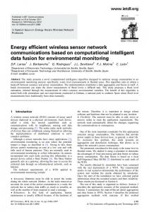
But there exists the hidden node problem. In hidden node problem, two terminals can be within the range of another terminal but out-of-range to each other. Two such terminals are said to be ‘hidden’ from each other. In cognitive networks, Index Terms - Cognitive Radio, Cognitive Wireless Sensor a primary user and cognitive user can be hidden to each Network, Localization. other, and there could be another primary user which is within the range of both, the primary and cognitive user. If I. I NT RODUCT ION this primary user is passive listening, it is not possible to Traditionally wireless networks are running with fixed identify the presence of this passive listening user through spectrum assignment policy regulated by government spectrum sensing. When a user is passive listening, it does agencies. Spectrum is assigned to service providers on a long not acknowledge or respond to any request. In this situation, term basis for large geographical regions. These spectrums hidden node problem arises in cognitive networks. As shown can only be allowed to be used by licensed users, but FCC measurements have indicated that 90 percent of the time, many licensed frequency bands remain unused [1]. In order to better utilize the licensed spectrum, the FCC has launched a Secondary Markets Initiative [2], whose goal is to remove regulatory barriers and facilitate the development PU1 Rp of secondary markets in spectrum usage rights among the Wireless Radio Services. This introduces the concept of dynamic spectrum allocation, which implicitly requires the PU2 Rc use of cognitive radios to improve spectral efficiency. The Disable Region CU1 inefficient usage of the existing spectrum can be improved through opportunistic access to the licensed bands without Fig. 1. Hidden Node Problem interfering with the primary users. Cognitive Radio (CR) is an intelligent wireless communication system that is aware of its surrounding environment. It dynamically adapts the in figure 1, PU2 is passively listening, and we can’t identify transmission or reception parameters of either a network or a the presence of PU2. If we disable CUs within the coverage node to achieve efficient communication without interfering radius of PU1, i.e. Rp , only, and PU1 is transmitting data to with primary users. In simple words, a cognitive radio network PU2, then CU1 can cause interference to this transmission. consists of primary and secondary users. The primary users 978-1-4577-1583-9/ 12/ $26.00 © 2012 IEEE
2012 International Conference on Computer Communication and Informatics (ICCCI -2012), Jan. 10 – 12, 2012, Coimbatore, INDIA
Multiple solutions to the hidden node problem have been provided, such as RTS/CTS handshake for WLAN [3], Busy Tone Multiple Access (BTMA) for a centralized system [4] and Dual Busy Tone Multiple Access (DBTMA) for ad hoc networks [5]. However, these solutions are implemented for networks where users are cooperative to each other, which is not the case for cognitive networks. In paper [6], GPS (Global Positioning System) enabled CUs cooperate to first estimate the environment based on back propagation method and then locate the position of PUs. In GPS technique, wireless node calculates its position by carefully timing the signals sent by the GPS satellites high above the Earth. But this solution can only be used when GPS service is present and is very expensive also. In this paper, we use cooperative sensing to identify the presence of PUs and then use the leveling and sectoring based approach for localization. Finally, disable region is identified considering the communication range of both primary and cognitive user, which avoids the hidden node problem. The cognitive users within the disabled region are sent to sleep mode until a free channel is detected in that area by spectrum sensing module. This avoids interference with the PUs and sleep & wake-up procedure will conserve energy. This approach is also suitable to Cognitive Wireless Sensor Network (CWSN) as battery life is a real constraint in these networks. The rest of this paper is organized as follows. Section II discusses the proposed localization algorithm. In Section III, simulation results are presented. And finally, Section IV summarizes the work done.
if their current level is higher than ‘H opC ount + 1’. The nodes that are having their level equal to or less than the ‘H opC ount + 1’ value of the received packet then they don’t update their current level value. In wireless communication most of the time Line of sight path is not available, and hence fading problems can occur. In such case hop-count ratio-based technique is preferred. If d is the distance between two levels and Rc is transmission range of a cognitive user then Rc > 2 ∗ d
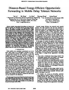
The total number of levels into the network is calculated based on the above equation. After leveling, each CU has its first coordinate as its level id, i.e. Li . To differentiate between the nodes within the same level, sensor network field is divided into equiangular regions called sectors as [9]. Each sector is uniquely identified with the help of sector ID. In order to inform their sector IDs to CUs, the CRB sends Sector Broadcast Packets (SBP) with directional antennas such that only nodes within a sector receive this broadcast. SBPs contain sector ID and information about the CRB. Sectors created with 30 degree regions are shown in figure 2. Now, we assign the sector WSN Field Sector 4 Sector 3 Sector 5
Sector 2
Sector 6
Sector 1
Sector 7
II. P ROPOSE D A PPROACH Proposed approach uses the leveling - sectoring based localization [7], [8] where each CU is identified by two coordinates, i.e. level id and sector id. First the entire cognitive network area is divided into various levels as in [9]. To divide sensor field into various levels, the Cognitive Radio Base Station (CRB) sends packets containing level ID for level 1 with minimum power level. All the nodes that receive this signal set their levels as 1. Next the CRB increases its signal power to reach the next level and sends packet containing next level ID. All the nodes that receive this signal, if have not already set their level ID, set their level to 2. This process continues until the CRB has sent signals corresponding to all levels. The number of levels into which the network gets divided is equal to the number of different power levels at which the CRB has transmitted the signal. Leveling can also be done using hop-count ratio-based technique. In this technique, hop-count of all the nodes is initialized to infinity. First sink broadcast packets with hop-count field set as zero. Nodes that directly receive these packets set their level as 1. These updated packets are again broadcast after incrementing hop-count field by 1. Nodes that receive these packets update their level to ‘H opC ount + 1’,
(1)
BaseStation
Clusters
Sector 12
Sector 8 Sector 11 Sector 9 Sector 10
Fig. 2.
Sector Representation
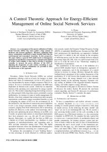
number, i.e. θj , as the second coordinate to cognitive users. Since the region was already divided into levels, the Sub−Sector
Fig. 3.
Sub-Sector Representation
sectoring created a number of sub-sectors as shown in figure 3. Now, the cognitive users know their location in terms of (Li , θj ). These cognitive users now do the cooperative sensing to identify the presence of PUs [10], [11]. In cooperative sensing, multiple cognitive users cooperate to reach an optimal global decision by exchanging and combining individual sensing information. This will increase the detection probability and reduce the detection time [4],
2012 International Conference on Computer Communication and Informatics (ICCCI -2012), Jan. 10 – 12, 2012, Coimbatore, INDIA
[12]–[16]. Cognitive users send their individual sensing information to the CRB. Once the presence of PU is detected, CRB calculates the relative position of PU in terms of (Li , θj ) based on the signal strength detected by CUs. According to Friis transmission equation, given two antennas and the power input to the transmitting antenna, Pt , the ratio of power available at the output of the receiving antenna, Pr , is given by 2
Pr = G t G r
λ
Pt (2) 4πR Where Gt and Gr are the antenna gain of the transmitting and receiving antennas, respectively, λ is the wavelength, and R is the distance between transmitter and receiver. Thus distance R is s P t Gt Gr λ2 (3) R= Pr (4π)2 As the distance is inversely related to the received power, CRB selects the CR with maximum received power. Thus, CRB identifies the closest CU, and assigns the same subsector location to the PU.
2) Add the Li , level id of the PU, in the disable level id list. 3) Add (DisableLevelC nt − 1) levels from (Li − 1) to (Li − (DisableLevelC nt − 1)) in the disable level id list. 4) Add (DisableLevelC nt − 1) levels from (Li + 1) to (Li + (DisableLevelC nt − 1)) in the disable level id list. Second step is to find the sectors that fall within the disable region. Steps to find the sector ids are: 1) Calculate the distance of the sub-sector midpoint from the CRB (6) DistanceF romBS = ((Li − 1) ∗ d) + d2 2) If CRB is inside the disable region, i.e. DistanceF romBS Rd , then a tangent can be drawn from the base station position as shown in figure 6. opposite According to Pythagoras Theorem, sin θ = hypotenuse , and θ can be calculated as
c
R p
Enabled CU
θ = sin−
Disabled CU PU
Fig. 4.
Scenario When Base Station is inside the disable region
1
opposite hypotenuse
(7)
Region to be disabled
Now, algorithm calculates the list of sub-sectors that are coming in this region and sends a message to disable all the CUs in those sub-sectors. Assume that the level id and sector id of the PU are (Li , θj ). First step is to find the levels that fall within the disable region. Steps to find the level ids are: 1) Calculate the number of levels to be disabled (DisableLevelC nt) at one side (up or down) with DisableLevelC nt =
Rd d
+1
(5)
4) Calculate the number of sectors to be disabled (DisableSectorC nt) at one side (left or right) with DisableSectorC nt =
θ SectoringAngle + 1
(8)
5) Add θj , the sector id of the PU, in the disable sector id list. 6) Add (DisableSectorC nt − 1) left neighbor sectors in the disable sector id list. 7) Add (DisableSectorC nt − 1) right neighbor sectors in the disable sector id list.
2012 International Conference on Computer Communication and Informatics (ICCCI -2012), Jan. 10 – 12, 2012, Coimbatore, INDIA Error% by varying PU% 100 "VaryingPU.txt" u 1:2 90 80 70
opposite
Error%
60
hypotenuse
50 40
theta
adjacent
30 20 10
Fig. 6.
0
Scenario When Base Station is outside the disable region
2
4
6
8
10
12
14
16
18
20
PU%
Fig. 7.
Now the list of all levels and sectors that fall in the disable region is known, and base station broadcast this list to all cognitive users. If CU’s level id and sector id, both are present in the broadcasted list, CU put itself to sleep until a wake-up message is sent from the base station. This approach disables the transmissions from all those users that are in the disable region, but it also disables some CUs that are outside the disable region and not causing interference to the PU. Future research can be done to improve the performance of the approach. Next Section discusses the simulation results of the approach discussed here.
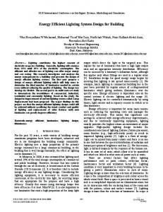
Error percentage by varying number of primary users
level error percentage is almost constant. The enabled CU count within the disable region for this scenario is always zero. Second scenario evaluates the performance of proposed approach by varying number of CUs in same network. In this scenario, number of PUs are fixed and taken as 10. Figure 8 Error% by varying number of CUs 100 "VaryingCU.txt" u 1:2 90 80 70
III. S IMUL AT ION R E SULT S Error%
60
In this section, we evaluate the performance of our proposed algorithm by means of simulation using MATLAB. The algorithm will be evaluated in a number of different scenarios. In simulation, the distance between two levels, d, is taken as 5 units and the sectoring angle, θ, as 30 degree. Wrong enabled CU that should be disabled and the error percentage of disabled CU count with respect to actual disabled CU count is calculated to evaluate the performance of the approach. The Error for disabled CU count is calculated with: q 2 (#C U DisableSim − #C U DisableActual) Error = (9) where #C U DisableSim is the number of CU that are disabled using the proposed approach, and #C U DisableActual is the number of CU that should be actually disabled. Error% is calculated with:
50 40 30 20 10 0 100
200
300
400
500
600
700
800
900
1000
#CU
Fig. 8.
Error percentage by varying number of CUs
shows that the error percentage is almost constant for all the cases, that means the performance of the algorithm is same for sparse and dense cognitive networks. The enabled CU count within the disable region for this scenario is also zero.
In next scenario, performance is evaluated by varying the network area. For this scenario, number of cognitive users and Error% = ∗ 100 (10) primary users are taken as 1000 and 10 respectively. Figure 9 shows the error percentage for this scenario. This graph shows that if network area is increasing for same number of In first scenario, the performance is evaluated by varying primary users, then the error percentage is decreasing. The the number of primary users in the network. For this enabled CU count within the disable region for this scenario scenario, number of cognitive users and grid size are taken is also zero for all the grid sizes. as 1000 and 2000 respectively. Figure 7 shows the error percentage for the scenario. According to this graph it is From figure 7, 8 & 9, it is clear that the performance of clear that as the number of PU are increasing in the network; proposed algorithm is same if cognitive users are increasing the error percentage is also increasing. But after certain in network. But if the increase in primary users is high, Error #T otalC U
2012 International Conference on Computer Communication and Informatics (ICCCI -2012), Jan. 10 – 12, 2012, Coimbatore, INDIA
available. Our algorithm locates the PU based on leveling and sectoring approach, and then disable region is identified to avoid interference to the primary user. Section III has covered the simulation results for the proposed algorithm, which shows that the proposed approach provide acceptable results. Specially, the count for wrongly enabled CUs is 0 for all the scenarios, which shows that the interference to the primary users is prevented, and thus this approach can be implemented in cognitive networks.
Error% by varying Network Area 100 "VaryingNetworkArea.txt" u 1:2 90 80 70
Error%
60 50 40 30 20 10
R E FE RE NCE S
0 1000
1200
1400
1600
1800
2000
Grid Size
Fig. 9.
Error percentage by varying network area
then the error percentage is increasing. If a network is full of primary users than there is no meaning in implementing cognitive network in that area. And thus proposed approach can be implemented to the practical scenarios. Finally, performance is evaluated by varying the sectoring angle as shown in figure 10. For this scenario, number of cognitive users and primary users are taken as 1000 and 10 respectively. This graph shows that for same number of Error% by varying Sectoring Angle
100 "VaryingSectorAngle.txt" u 1:2 90 80 70
Error%
60 50 40 30 20 10 0 10
20
30
40
50
60
Sectoring Angle
Fig. 10.
Error percentage by varying Sectoring Angle
primary and cognitive users in a network area, as the sectoring angle is increasing, the error percentage is increasing linearly. But selection of the sectoring angle depends upon the type of antenna used at the base station and other implementation constraints. For this reason, in all other simulation scenarios, 30 degree sectoring angle is selected. For all the angles in this scenario, enabled CU count within the disable region is 0. IV. C ONCL USION In this paper, we have proposed the Energy Efficient Localization of Primary Users for Avoiding Interference in Cognitive Networks. This approach can be implemented in networks where GPS like localization techniques are not
[1] FCC Spectrum Policy Task Force. Fcc report of the spectrum efficiency working group. Nov. 2002. [2] Secondary markets initiative. http://wireless.fcc.gov/licensing/secondarymarkets/. [3] Wireless lan medium access control (mac) and physical layer (phy) specifications. ANSI/IEEE Std 802.11:1999 (E) Part 11, 1999. [4] F. Tobagi and L. Kleinrock. Packet switching in radio channels: Part ii–the hidden terminal problem in carrier sense multiple-access and the busy-tone solution. Communications, IEEE Transactions on, 23(12):1417 – 1433, December 1975. [5] Z.J. Haas and Jing Deng. Dual busy tone multiple access (dbtma)a multiple access control scheme for ad hoc networks. Communications, IEEE Transactions on, 50(6):975 –985, June 2002. [6] Lin Liu, Zhengyi Li, and Chi Zhou. Backpropagation-based cooperative localization of primary user for avoiding hidden-node problem in cognitive networks. International Journal of Digital Multimedia Broadcasting, page 9, 2010. [7] G. Lakshmi Phani, K. Venkat Sayeesh, K. Vinod Kumar, and G. Rama Murthy. Erfla: Energy efficient combined routing, fusion, localization algorithm in cognitive wsn. In Wireless And Optical Communications Networks (WOCN), 2010 Seventh International Conference On, pages 1 –5, 2010. [8] M.K. Sharma, A. Singal, P.G. Vijay, and R. Murthy. Minimal energy consumption in the localization of a sensor network. In Sustainable Energy Technologies (ICSET), 2010 IEEE International Conference on, pages 1 –4, 2010. [9] A. Mirza and R.M. Garimella. Pascal: Power aware sectoring based clustering algorithm for wireless sensor networks. In Information Networking, 2009. ICOIN 2009. International Conference on, pages 1 –6, 2009. [10] A. Ghasemi and E.S. Sousa. Collaborative spectrum sensing for opportunistic access in fading environments. In New Frontiers in Dynamic Spectrum Access Networks, 2005. DySPAN 2005. 2005 First IEEE International Symposium on, pages 131 –136, 2005. [11] G. Ganesan and Y. Li. Cooperative spectrum sensing in cognitive radio networks. In New Frontiers in Dynamic Spectrum Access Networks, 2005. DySPAN 2005. 2005 First IEEE International Symposium on, pages 137 –143, 2005. [12] G. Ganesan and Li Ye. Cooperative spectrum sensing in cognitive radio, part ii: Multiuser networks. Wireless Communications, IEEE Transactions on, 6(6):2214 –2222, 2007. [13] G. Ganesan and Ye Li. Cooperative spectrum sensing in cognitive radio, part i: Two user networks. Wireless Communications, IEEE Transactions on, 6(6):2204 –2213, 2007. [14] J.N. Laneman, D.N.C. Tse, and G.W. Wornell. Cooperative diversity in wireless networks: Efficient protocols and outage behavior. Information Theory, IEEE Transactions on, 50(12):3062 – 3080, 2004. [15] Z.J. Haas and Jing Deng. Dual busy tone multiple access (dbtma)a multiple access control scheme for ad hoc networks. Communications, IEEE Transactions on, 50(6):975 –985, June 2002. [16] G. Ganesan and Ye Li. Agility improvement through cooperative diversity in cognitive radio. In Global Telecommunications Conference, 2005. GLOBECOM ’05. IEEE, volume 5, pages 5 pp. –2509, 2005.