scheme in which both horizontal and vertical clusters of zeros are iden- tified and used ... architecture, called variable refresh period, uses multiple refresh periods for dif- ... and has been refined in [9] by employing a refresh counter for each row, plus a ... period, referred to a system with 16KB of L1 Cache and no L2 cache.
Energy-Efficient Value-Based Selective Refresh for Embedded DRAMs K. Patel1 , L. Benini2 , Enrico Macii1 , and Massimo Poncino1 1 2
Politecnico di Torino, 10129-Torino, Italy Universit` a di Bologna, 40136 Bologna, Italy
Abstract. DRAM idle power consumption consists for a large part of the power required for the refresh operation. This is exacerbated by (i) increasing amount of memory devoted to cache, that filter out many accesses to DRAM, and (ii) increased temperature of the chips, which increase leakage and thus data retention times. The well-known structured distribution of zeros in a memory, combined with the observation that cells containing zeros in a DRAM do not require to be refreshed, can be constructively used together to reduce the unnecessary number of required refresh operations. We propose a value-based selective refresh scheme in which both horizontal and vertical clusters of zeros are identified and used to selectively deactivated refresh of such clusters. As a result, our technique significantly achieves a net reduction of the number of refresh operations on average of 31%, evaluated on a set of typical embedded applications.
1
Introduction
Embedded DRAM (EDRAM) is viewed as viable design option for applications with significant memory requirements, tight performance constraints and limited power budgets. Embedded DRAM has lower density, requires a more expensive mask set and fabrication process, but it offers a drastically improved energyper-access [1]. The energy efficiency of EDRAMs advantage may be reduced, or even worse, compromised, if adequate countermeasures are not taken to address its idle power consumption, caused mainly by the periodic refresh operation. Refresh is a more serious problem for EDRAMs than for standard DRAMs for two main reasons. First, technology options to reduce cell leakage cannot be as aggressively pursued in EDRAM as in standard DRAMs, because of cost reasons, and fundamentally as a consequence of the tradeoff between efficient logic and efficient memory. Second, the presence of fast switching logic on the same die causes higher-temperature operation, which increases leakage, thereby implying an increase in refresh rate. From the architectural viewpoint, faster refresh rates imply larger idle power for EDRAM. The importance of idle power is magnified by the fact that DRAMs are often used with a low duty cycle of busy periods, since DRAM accesses are filtered by the higher levels of the memory hierarchy (i.e, fast and small SRAM based caches). For these reasons, several researchers have proposed techniques V. Paliouras, J. Vounckx, and D. Verkest (Eds.): PATMOS 2005, LNCS 3728, pp. 466–476, 2005. c Springer-Verlag Berlin Heidelberg 2005 �
Energy-Efficient Value-Based Selective Refresh for Embedded DRAMs
467
for idle power minimization in EDRAM memories [4], which are also applicable to generic DRAMs [5]. Most of these techniques aim at providing very low-power shutdown states, either with loss of information or with significant access time penalty. Alternative approaches aim at reducing power less aggressively than with shutdown, while at the same time minimizing access time overhead [9, 11]. In this paper, we propose a low-overhead refresh power reduction technique based on the concept of selective refresh. We exploit the well-known dominance of zero bits in the data stored in DRAM, and by adding a limited amount of redundant storage and logic (which is the overhead in our technique) to index the memory blocks that contain a zero value, so as to eliminate refresh to these blocks. As a result, our technique significantly reduces the number of refresh operations, decreasing idle power. One important design exploration parameter is the granularity at which we apply zero value detection and tagging. In this work, we propose two alternative mechanisms, namely horizontal and vertical zero clustering and we analyze the granularity at which they can be applied. Our results, demonstrate that an average reduction of 31% of the refresh operations, measured for different granularities.
2
Previous Work
The non-uniform distribution of values in memories have been exploited in several ways, although this property has been mainly used in the context of caches, with the objective of reducing the average access time or the total energy by reducing the cost of memory reads using the “common-case” principle. The frequent value (FV) cache [7] is based on the analysis of application data usage, that allows to identify few frequently accessed data values; these are stored in a small buffer, resulting in frequent access of the small buffer. The experimentally observed dominance of zeros in a cache has been exploited by the value-conscious cache [8], where a sort of hierarchical bitline scheme is used to avoid discharging of the bitline whenever a zero value is stored. A similar approach is used in the dynamic zero compression (DZC) architecture [6], where, zero bytes are encoded using one bit, achieving energy reduction while accessing zero bytes in cache. Concerning architectural techniques that aim at reducing the energy impact of refresh, Ohsawa et al. [9] propose two refresh architectures. The first one, called selective refresh, is based on the observation that data need to be retained (and thus refreshed) only for the duration of their lifetimes. The difficulty in the implementation of this architecture lies in that it is not immediate to extract this information, which may require some support by the compiler. The second architecture, called variable refresh period, uses multiple refresh periods for different regions of the array, based on the fact that the data retention time of the cells is not constant. This property was first exploited at the circuit level [10], and has been refined in [9] by employing a refresh counter for each row, plus a register that stores the refresh period of a given row. This idea has been elaborated into a more sophisticated scheme in [11], where the idea variable refresh period is applied on a granularity (a “block”) smaller than a row.
468
3
K. Patel et al.
Value-Based Selective Refresh
3.1
Motivation
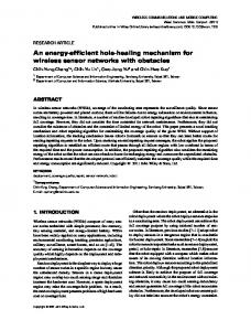
The technique proposed in this paper is motivated by the observation of two properties of DRAM memory systems. The first one is a consequence of the fact that, since most of the memory references are filtered out by caches, only few accesses go to main memory (normally a DRAM). This causes the contribution of idle power consumption to become dominant, since refresh is a mandatory operation. The plot in Figure 1 endorses this fact: it shows, for a set of benchmarks, the split between refresh and access energy as a function of the refresh period, referred to a system with 16KB of L1 Cache and no L2 cache. We notice that the relative importance of refresh becomes dominant for refresh periods around few million cycles; assuming a 200MHz frequency typical of a SoC, this figure is equivalent to a few tens of ms, comparable to the refresh periods of common EDRAM macros [2, 3]. Notice that the addition of a L2 cache would make refresh energy even more dominant.
Refresh Accesses [%]
120.00 100.00 80.00 60.00 40.00
adpcm epic g721 gsm jpeg pegwit rasta
20.00 0.00 250K
500K
1M
2M
4M
Refresh Period [Cycles]
Fig. 1. (a) Refresh vs Access Energy Split (b) Distribution of Zero Clusters
The second property is that memories, in general, tend to exhibit structured distribution of 0’s and 1’s. This also holds for DRAMs, that besides the classical high horizontal occurrence of 0’s (e.g., a large number of zero bytes), exhibit an even more relevant vertical occurrence of 0’s. We will use the term clusters to denote these subsets of rows or columns. Figure 1-(b) shows the occurrence frequency of 0’s in a DRAM, relative to a set of benchmarks. Values are relative to different granularities (8, 16, and 32) of 0-valued clusters, either vertically or horizontally. The plot shows that, while the number of horizontal zero clusters decreases quite rapidly as the cluster size increases, vertical clusters are more frequent and do not decrease much for larger cluster sizes: on average, 38% of the vertical 32-bit clusters contain all zeros. Our idea is to use the latter property to reduce the number of refresh operations by observing that cells containing a zero do not need to be refreshed. Since they can be grouped into clusters, it is possible to avoid the refresh of an entire
Energy-Efficient Value-Based Selective Refresh for Embedded DRAMs
469
cluster. In other words, we transform the operation of refresh, that is is done independent of the value contained in the cell, into a value-dependent operation. From the architectural standpoint, our value-based selective refresh consists of grouping 0’s in clusters. The information regarding the value of each cluster is stored in an extra DRAM cell. This cell stores a one if all bits in the cluster are zero, and zero otherwise. From the observation of the data of Figure 1-(b), clustering of zeros can be either horizontal or vertical, and hence, in this paper, we investigate two different approaches to clusters zero cells. 3.2 Horizontal Zero Clustering(HZC) Our approach to cluster zeros in the horizontal direction is similar to one proposed by Villa et. al. [6], in which clustering of zeros is exploit to reduce dynamic power dissipation in caches (SRAM). Figure 2-(a) shows the conceptual architecture of HZC. Each word line is divided in number of clusters each one having its Zero Indicator Bit (ZIB). The ZIBs are placed in extra columns in the cell array, depicted as vertical gray stripes in Figure 2-(a). As shown in Figure 3-(a), depending on the content of ZIB cell, the local word line of the corresponding cluster can be disconnected from the global word line. The operations of the memory with HZC architecture can be summarized as follows.
Fig. 2. Architecture of (a) Horizontal and (b) Vertical Zero Clustering
– Refresh: During the refresh operation, the local wordline of the cluster is connected or disconnected from the global wordline based on the content of ZIB cell. Figure 3-(a) shows that refresh is not performed if the ZIB is one (M2 is turned off, and M1 is turned on, grounding the local word line). – Read: Read operation similar to refresh. During read, the ZIB is read and depending on its value, the bits in the cluster will be read or not. If ZIB stores a one, then the bits in the cluster are not read (we know that they are all zero), whereas if it stores a zero they will be read out. – Write: During write operation the ZIB bit is updated when its cluster is written. The Zero Detect Circuit (ZDC) will detect if all cluster bits are zero; if so, a ’1’ is written into the ZIB. The design of ZDC is very similar to the to the one found in [6], and thus it is not reported here.
470
K. Patel et al. ZIB BitLine
BitLine 1
GND
Global WordLine
BitLine n
Local WordLine
M3 M2
M1
1 C
…
n
ZIB
Fig. 3. (a) ZIB circuit [5] (b) Refresh Period Operations : VZC Architecture
Notice that during the read and refresh operations the ZIB is read; since the read operation is destructive, the proposed scheme imposes a small read time overhead. When the ZIB is ’0’, the cluster bits have to refreshed along with ZIB, during the refresh operation. Referring to Figure 3-(a), we notice that, during refresh, the bitline is pre-charged to Vdd /2 thus partially charging the capacitance C of the ZIB and hence possibly turning transistor M2 off and hence cutting off the local wordline of rest of the n bits. If we wait to restore the value of ZIB, the local wordline will again be active and connecting the cluster bits to their bitlines. When the ZIB is ’1’, this indicates a zero cluster. This will cut off the local wordline of the cluster during read. Thus, the sense amplifiers of the cluster’s columns will remain in a meta-stable state. To avoid this problem, the sense amplifier design has to be modified, as done in [6] (the modified circuit is not shown here for space reasons). 3.3
Vertical Zero Clustering(VZC)
Vertical Zero Clustering(VZC) aims at detecting and exploiting the presence of clusters of zeros in columns of the DRAM array. Figure 2-(b) shows the conceptual architecture for VZC. Depending on the granularity of clustering every n rows will have one Zero Indicator Row (ZIR). Each ZIR contains one ZIB for each column in the DRAM array. Since we add one ZIR for n rows, we need a separate decoder for ZIRs, which will use higher-order address bits to access it, depending on the granularity. We also add an additional column to the array, containing a set of dirty bit indicators, one for each ZIR. These bits will be used to track writes and to ensure that the ZIB bits are correctly updated (as discussed in detail later). Similarly to HZC, VZC also requires support circuitry for each column of the array. These circuits are shown in Figure 4-(a) and Figure 4-(b), that are used in different moments by the different operations on the DRAM. Memory operations in the VZC can be summarized as follows. – Read: Read is performed as a normal read, the only difference being the presence of the circuit depicted in Figure 4-(a).
Energy-Efficient Value-Based Selective Refresh for Embedded DRAMs
471
Fig. 4. (a) Selective Refresh Circuit: VZC (b) Write Circuit of ZIB
During read operation, the Read signal is held high, ensuring that the transistor M1 is turned on. Then, a normal pre-charge takes place, followed by the read of the desired cell. Notice that the ATD signal in the figure is used only during refresh to selectively disable the pre-charge of bitlines. – Write: Write is also done in the usual way. Notice that as long as data is just read from memory, the status of the clusters will not change. Conversely, when a datum is written into the memory, it may modify the status of the clusters; therefore, the status of the ZIB must be changed accordingly. This may be a problem, since, in order to change the status of the ZIB, all rows of the cluster must be read. Rather, we avoid this overhead by postponing the ZIB update operation until the next refresh operation by zeroing the ZIB of the cluster corresponding to the current write address. This operation also sets the dirty bit of that ZIR by writing ’1’ to it. Based on the value of the dirty bit, the next refresh operation of this cluster will determine the latest status of ZIBs. – Refresh: Refresh operation has two modes. One is the normal refresh operation where zero clusters are not refreshed and the other one is the ZIB update mode. • Normal Refresh: Before starting the refresh of the first row of the cluster, corresponding ZIR is read. Reading of ZIR is triggered by the Address Transition Detection (ATD) signal. The ATD signal goes to one every n rows that are refreshed, that is, when we cross the boundary of a ZIR. The ATD signal triggers the ZIR read operation using the ZIR decoder, shown in Figure 2-(b). As shown in Figure 4-(a), ATD will turn on transistor M2 and depending on the value of ZIB the capacitor will be charged or discharged. At the end of the read operation on ZIR, ATD will go low. If the ZIB is ’1’, a ’0’ will be produced at the output of inverter of Figure 4-(a). The read signal will be held low during the refresh operation, so that the transmission gate M3 will be turned on, putting also tran-
472
K. Patel et al.
sistor M6 on. This, in turn, will turn the transistor M1 off cutting of the pre-charge from bitline. Hence if the ZIB is ’1’ the pre-charge will be for that particular column, will remain disabled for the next n rows. Therefore, during row-based refresh operation, the bits of this column belonging to the cluster will not be refreshed. Conversely, if the ZIB is ’0’ this results in discharging the capacitance, forcing the output of the inverter to ’1’. This will turn M6 off and and M1 on, so that a normal refresh will occur. • ZIB update mode: During the ZIB update mode, the status of the clusters has to be determined to update the value of ZIB. This part of the circuit is shown in Figure 4-(b). As explained above, before starting to refresh of the first row of a cluster, the content of the ZIR for that cluster is read by raising ATD high. Reading ZIR will read the dirty bit corresponding to that ZIR. If the dirty bit is is set (i.e., the status of the ZIR is unknown) this will turn transistor M2 on using the NAND gate. This will result in charging the capacitance C. This will, in turn, result in putting ’1’ at the Write Output, using transistor M1. All these operations occur when the ZIR is read. Assuming ZIR is reset and its dirty bit is set, the regular row based refresh will follow the ZIR read operation. Notice that the ATD signal will go low before the row-based refresh starts. During refresh if any of the bits of this given column is ’1’, then it will put transistor M3 on and it will ground all the charged capacitances, setting output of the inverter to ’1’. This will make Write O/P to go to ’0’. For those ZIRs which have the dirty bit set, the value of Write O/P will be written back to the corresponding ZIR at the end of the refresh of all the rows of the cluster. The end is actually detected, again, by ATD, since after the refresh of the last row of the cluster it will move to the first row of the next cluster. The sequence of operations occurring during refresh of the VZC DRAM is summarized in Figure 3-(b). When refreshing the first row of the cluster, refresh operation will be performed after ZIB update and ZIR read. The following n − 1 row refresh operations will be normal refresh operations. Notice that since the content of the ZIR is built based on the content of DRAM cells, it has to be refreshed as well. This is done when reading the ZIR, and does not require an explicit refresh. 3.4
Write Impact on Refresh
In the VZC architecture, whenever a write comes, it resets the ZIR of the cluster to which this write belongs and sets the dirty bit. Hence, on the next refresh, this cluster will have to be refreshed. If during the same refresh period another write comes to the same cluster then it will not change the status of ZIR since this cluster has already been declared as “dirty”. Instead, if the write goes to another cluster it results in destroying another cluster by reseting its ZIR. Hence, on the next refresh this cluster will have to be refreshed as well. If many writes
Energy-Efficient Value-Based Selective Refresh for Embedded DRAMs
473
are distributed over different clusters this will jeopardize the opportunities to save refresh to these clusters. This is also strictly related to the cluster size. Experiments show that as we move towards coarser granularity, the percentage of dirty clusters increases. This is due to the fact that, even though distribution of writes to different clusters is reduced, the total number of clusters is reduced. In general, however, this percentage remains quite small and hence, dirty writes do not reduce significantly the impact of VZC.
4
Overhead Analysis
Both HZC and VZC architectures have some area and timing overhead. Here we briefly discuss it with approximate quantification. Concerning area, Table 1 summarizes different components contributing to area overhead for HZC and VZC architectures for different cluster granularities n. The percentage overhead is with respect to the area of that component in a regular, non-clustered DRAM. Table 1. Relative Percentage Area Overhead HZC VZC Components n=8 n=16 n=32 n=8 n=16 n=32 Data Matrix 37.5 18.7 9.3 12.5 6.25 3.12 Bitline 12.5 6.25 3.12 100 Wordline 100 12.5 6.25 3.12 Sel. Refresh negligible constant overhead Row Decoder No Overhead 9–10 3–4 1–2
– Data Array: For the data array in HZC architecture every n bits we have three extra transistors (2 n-MOS and 1 p-MOS, Figure 3-(a)), i.e., an overhead of 3/n. In the VZC architecture we have an extra additional row for every n rows, hence an overhead of 1/n. Notice that in HZC architecture the p-MOS transistor drives the local wordline, and depending on the granularity of the cluster, it has to be wide enough to drive it without introducing an extra delay in reading. – Bitlines: In the HZC architecture, we have an extra bitline for every n bitlines, while in the VZC architecture we have an extra wire running parallel to every bitline (Figure 4-(a)). Though this wire is not an extra bitline, for the sake of the overhead calculation we considered it as a bitline overhead. – Wordlines: Due to divided wordline type of architecture (Figure 3-(a)) of HZC, we have extra local wordlines, which has total length per row approximately equal to the length of the global wordline. In the VZC architecture we have an extra row for every n rows.
474
K. Patel et al.
– Row Decoders: While the HZC architecture does not need an extra row decoder, the VZC architecture has an extra row decoder for decoding ZIRs. Though the complexity of this extra row decoder is significantly smaller than the main row decoder, its cost depends on n. As shown in the table, with respect to the regular row decoder this extra row decoder has marginal overhead. And its contribution to overall area overhead is very small, since the dynamic logic based decoders themselves have complexity of 5 to 8 % with respect to data matrix (considering transistor counts). Delay, on the contrary, is slightly more critical for read operations. For the HZC architecture read operation has a slight increase in delay since the ZIB has to be read out to determine the value of the rest of the n bits. Whereas, in case of VZC architecture, read operation is performed in the normal way, and hence there is no visible increase in delay. Concerning the write operation, in the HZC scheme during each write the zero detect circuit has to determine if there are zero clusters or not, before committing the write to the lines. Hence there is an increase in write time, determined by the delay of the zero detect circuit. Conversely, in the VZC architecture, write operation is carried as normally, followed by the resetting ZIR and the setting of dirty bit. Hence, there is no sizable delay increase during the write operation as well. Overall, the overhead of the VZC architecture is smaller, and, even more important, it does not impact normal read and write operations. This fact, coupled with the statistics of Figure 1-(a) seems to make VZC a more competitive architecture than HZC.
5
Experimental Results
For our experiments we have used a modified version of the SimpleScalar3.0/PISA [12]. All our experiments are run using sim-outorder. We configured simulator to have separate L1 Instruction (direct mapped) and Data cache (4way set associative), both of size 16KB with 32-byte block size. L2 cache has been disabled, since the relatively limited execution time of the applications did not allow to see sufficient traffic towards the DRAM. During all our experiments we have kept data retention time of a DRAM cell to be one million CPU cycles. Assuming a 200MHz frequency of a typical SoC, this is equivalent to 5 milliseconds. We have used the MediaBench suite [13], which includes various multimedia, networking and security related applications. Most of the benchmarks have separate encoding and decoding applications. Figure 5 plots the percentage of refreshes avoided by two the HZC and VZC architectures, for different granularities of cluster. The plots correspond to encoding and decoding applications of the MediaBench benchmarks, Notice that the reported values already account for the refresh overheads brought by HZC and VZC, and are in fact equivalent to reductions of refresh energy. In the plots, x v represent the relative savings brought by VZC architecture, where x is the granularity of horizontal (h) or vertical (v) clustering. As can be seen from plots, at the byte granularity both VZC and HZC bring almost the same percentage of savings, but as we move towards granularity of 16 and
Energy-Efficient Value-Based Selective Refresh for Embedded DRAMs
475
50
50 8_v 8_h 16_v 16_h 32_v 32_h
45 40 35 30
Encode-128
8_v 8_h 16_v 16_h 32_v 32_h
45 40 35 30
25
25
20
20
15
15
10
10
5
5
0
Decode-128
0
adpcm
epic
g721
gsm
jpeg
pegwit
rasta
adpcm
epic
g721
gsm
jpeg
mpeg2
pegwit
Fig. 5. (a) Relative Refresh Energy Savings in Encoding (b) Decoding applications
32 bits, the dominance of VZC architecture becomes visible. As the plots show, savings with VZC architecture for granularities of 8,16 and 32 bits are not too different, whereas in case of HZC architecture the difference is large. The average savings for the best architectures are 26.5% for HZC (cluster size = 8) and 33% for VZC (cluster size = 32). Notice that VZC with cluster size of 32 provides the best results, due to much smaller overhead.
6
Conclusions
In this paper, we have proposed two value-conscious refresh architectures suitable for embedded DRAMs. Based on the observation that zeros do not need to be refreshed, we group bits into clusters to avoid refresh of entire cluster. We have explored clustering in both horizontal and vertical directions, and various cluster sizes. Our experiments show that as we move towards higher granularity vertical clustering become more effective than horizontal one. Due to smaller overhead, for higher granularity vertical clustering offers substantial advantage. Experimental results show that the best overall architecture, that is, vertical clustering with cluster size of 32 provides a 33% reduction of refresh energy, evaluated on a set of embedded multimedia applications.
References 1. D. Keitel-Schulz, N. Wehn, “Embedded DRAM Development: Technology, Physical Design, and Application Issues,” IEEE Design and Test, Vol. 18, No. 3, pp. 7–15, May 2001. 2. C.-W. Yoon et al., “A 80/20MHz 160mW Multimedia Processor integrated with Embedded DRAM MPEG-4 Accelerator and 3D Rendering Engine for Mobile Applications,” ISSCC’04, pp. .202- 522, Feb. 2004. 3. R. Woo, et al. “A Low-Power Graphics LSI integrating 29Mb Embedded DRAM for Mobile Multimedia Applications,” ASPDAC’04,pp. 1758–1767, Feb. 2004. 4. F Morishita, et al., “A 312MHz 16Mb Random-Cycle Embedded DRAM Macro with 73/spl mu/W Power-Down Mode for Mobile Applications,” ISSCC’04,pp. .202- 522, Feb. 2004.
476
K. Patel et al.
5. V. Delaluz, et al., “Hardware and Software Techniques for Controlling DRAM Power Modes,” IEEE Transactions on Computers, Vol. 50, No. 11, Nov. 2001, pp. 1154 - 1173. 6. L. Villa, M. Zhang, K. Asanoivc, “Dynamic zero compression for cache energy reduction,” Micro-33: 33rd International Symposium on Microarchitecture, Dec. 2000, pp. 214–220. 7. Y. Zhang, J. Yang, and R. Gupta, “Frequent Value Locality and Value-Centric Data Cache Design,” ASPLOS’00, Nov. 2000, pp. 150–159. 8. Y.J. Chang, C.L. Yang, F Lai, “Value-Conscious Cache: Simple Technique for Reducing Cache Access Power,” DATE04,Feb. 2004. pp. 16–21. 9. T. Ohsawa, K. Kai, K. Murakami, “Optimizing the DRAM Refresh Count for Merged DRAM/Logic LSIs,” ISLPED’98,Aug. 1998, pp. 82–87. 10. Y. Idei, et al., “Dual-Period Self-Refresh Scheme for Low-Power DRAMs with OnChip PROM Mode Register,” IEEE Journal on Solid-State Circuits, Vol. 33, No. 2, Feb. 1998, pp. 253–259. 11. J. Kim, M.C. Papaefthymiou, “Block-Based Multiperiod Dynamic Memory Design for Low Data-Retention Power,” IEEE Transactions on VLSI Systems, Vol. 11, No. 6, Dec. 2003, pp. 1006–1018. 12. SimpleScalar home page, http://www.simplescalar.com/ 13. C. Lee, M. Potkonjak, W. Mangione-Smith, “MediaBench: A Tool for Evaluating and Synthesizing Multimedia and Communications Systems”, International Symposium on Microarchitecture, Dec. 1997, pp. 330–335.