10, NO. 5, MARCH 2015. ISSN 1819-6608 ... ENERGY EFFICIENT WIRELESS CLASSROOM AND BUS MONITORING. SYSTEM ... can be detected using low-cost radio technology Zig Bee, ... operating on top of the IEEE 802.15.4 standard[2].
VOL. 10, NO. 5, MARCH 2015
ARPN Journal of Engineering and Applied Sciences
ISSN 1819-6608
©2006-2015 Asian Research Publishing Network (ARPN). All rights reserved.
www.arpnjournals.com
ENERGY EFFICIENT WIRELESS CLASSROOM AND BUS MONITORING SYSTEM Vijaya Baskar V. and Sakthivel E. Sathyabama University, Jeppiaar Nagar, Rajiv Gandhi Salai, Chennai, India
ABSTRACT The main objective of this work is to develop a system for monitoring the class room to update the students’ strength in the class room automatically. The students entry and exit can be tracked through the IR transceiver pair. This system also uses the RF reader to find the active staff present in the class. Then finally the desired information can be sent to the control centre, which may be the principal or HOD room. The control centre and class room module communicates through the ZigBee; thereby the information monitored is stored in the centre PC. The purpose of monitoring is to find the number of students present in the class in each hour. This system minimizes energy consumption and human intervention. This system can also be used to monitor the bus arrival time at the university campus. The ‘IN’ time, ‘OUT’ time of a bus and the number of persons boarding on the buses can also be monitored and these data can be sent to the admin location. Keywords: classroom, IR pair, RFID, Zig Bee transceiver, energy efficient, wireless.
1.
INTRODUCTION This monitoring system is mainly used for colleges and schools to monitor the classroom in real time. Most of the monitoring system in schools and colleges consume more man power. As of now staff members will mark students presence and absence in a register and the same will be updated to find the total student present in a day. This will delay the work and also not accurate. So it is important to develop a system to reduce the manpower and to get accurate data to the admin people. The admin people can also monitor the classroom to find the active master in any classroom this will be useful to locate a staff whenever there is an emergency or need. On the receiver side, the signal can be received using ZigBee and interfaced to pc. Based on the Zig Bee standard, any number of class rooms can be connected together in a secure and reliable mesh network and monitored via existing asset management systems or monitoring software. 2.
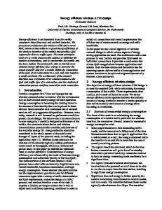
OVERVIEW OF SYSTEM DESIGN In this paper energy efficient wireless classroom monitoring system, which allows department heads and principal to monitor the class room from the remote location. The short range of wireless communication is to overcome network issues by Hopping messages up and down the network. In this way, ranges of the class room can be detected using low-cost radio technology Zig Bee, which enables wireless service coverage of 350m or more. The RFID data collected from the current location will be sent to the admin location. The system has a Master unit, which is located at the admin location and slave units, which are kept in class rooms. a) Master unit Master module is placed in Prohibited area like principle or HOD room and it transmits ASCII codes to receive information from the slave unit through ZigBee transmitter as shown in Figure-1.It consist of a Zig Bee module, which is connected with a PC using RS 232.This
module collects information from slave modules and store it in the PC.
ZIGBEE
Personal Computer
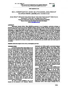
Figure-1. Master unit. b) Class room module Class room module is placed in the class rooms, which counts the number of students entered using IR pair. The RFID reader collects the staff information from the RFID tag, which is carried by the staff member, then the Zig Bee module will send both staff information and the number of students present in the class to the control centre [9]. The information sent in the form of ASCII code. These codes are received by the master unit and updated in the system. When the IR pair start counting the people, the load automatically turns on by the microcontroller. The class room module is shown in Figure-2. c)
Bus module Bus module is placed in the bus. When any person enters the bus via front staircase or back stair case, the IR pair count the number of persons[1][8]. The ZigBee module send the number of persons on board in each bus to the control centre. By using this module the total number of persons entered in to the campus by the university bus on a day can be obtained exactly. This exact count can be updated to mess in time to avoid wastage of food. The bus module is shown in Figure-3.
2172
VOL. 10, NO. 5, MARCH 2015
ARPN Journal of Engineering and Applied Sciences
ISSN 1819-6608
©2006-2015 Asian Research Publishing Network (ARPN). All rights reserved.
www.arpnjournals.com
Figure-4. System view.
Figure-2. Class room module. 3.
HARDWARE DESCRIPTION The system contains three major hardware components, Microcontroller, RFID module and ZigBee module.
Figure-3. Bus module. d) System view This system is also used in mesh network. More number of class rooms can be connected in single mesh network as shown in Figure-4. The model we have done is based on single class room. Many number of class can be connected with the single master unit[10]. This can be done by creating nodes and connecting via nodes. The nodes are active when they are working and go to sleeping mode when ther are not used, therby saving power. In this way more number of buses can be connected to the master unit. The bus numbers are linked with the ZigBee mac id. The ZigBee will have unique mac id. Each bus will throw this unique id. The numbers and routes are stored in the database corresponds to this unique mac id.
a) Microcontroller PIC16F74 Microcontroller with a wide operating range has been selected for sensing the signals and to control the output signals. This microcontroller has a wide operating range, consumes less power, typically less than 2mA at 5 volt supply. The PIC16F74 features 8 channels of 8-bit Analog-to-Digital (A/D) converter with 2 additional timers, synchronous serial port can be configured as either 3-wire Serial Peripheral Interface (SPI™) or the 2-wire Inter-Integrated Circuit (I²C™) bus and a Universal Asynchronous Receiver Transmitter (USART), 2 capture/compare/PWM functions. b) Zig Bee and IEEE 802.15.4 ZigBee is developed on the basis of IEEE 802.15.4 standards. It allows batteries to last up to years using primary cells (low cost) without any chargers (easy installation and low cost). The ZigBee standard provides security, network and application support services operating on top of the IEEE 802.15.4 standard[2]. The same program is loaded onto all of the ZigBee modules. The way that the program functions, is determined by the way the dip switches on the module is set. The dip switch configuration determines the address of a module as well as its role. An address of zero sets a node up as a coordinator. The coordinator is directly connected to a PC via RS232. The virtual comport driver must be installed for proper functioning. The router module tries to connect to the coordinator. If it is successful the program continues. If not the module continues to try to connect to the coordinator. The module reads its A/D inputs at regular intervals. ZigBee technology takes full advantages of the IEEE 802.15.4 standards and extends the capability of this new radio standard by defining a flexible and secure network
2173
VOL. 10, NO. 5, MARCH 2015
ARPN Journal of Engineering and Applied Sciences
ISSN 1819-6608
©2006-2015 Asian Research Publishing Network (ARPN). All rights reserved.
www.arpnjournals.com layer that supports a variety of architectures to provide highly reliable wireless communication. ZigBee technology also offers simplicity and cost-effective with wireless technology. ZigBee is all set to provide the consumers with ultimate mobility, flexibility, and ease of use by building wireless intelligence and capabilities into every day devices. c)
RF ID RFID is Radio Frequency Identification Device. It is a fast, affordable and automatic identification technology that uses radio frequency (RF) to transfer data between a RFID reader and a RFID tag[3][7]. An RFID tag is a small object, such as an adhesive slicker, that can be attached to or incorporated into a product. RFID tags contain antenna and magnetic strip to enable them to receive and respond to radio-frequency queries from the interrogator. The tag is generally made of an 1C. The IC will include memory and some form of processing capability. The tags can be classified in to two types 4.
Active tags -With internal power supply Passive tags -Without internal power supply
ALGORITHAM DESCRIPTION
a)
Class room control unit The IR pair connected to the microcontroller port throw the pull-up resistors. It is important to find weather a student is entering in to the class or leaving from the class. So two IR pair has been used. The out put of the IR module is given as input to the counter, which is on chip with PIC microcontroller. When a person entering into the class room the IR pair generate a pulse and the counter will be incremented to indicate the student is entering in to the class. When the first IR pair i.e. IR1 detects before the second IR pair i.e. IR2 the counter will be incremented [6]. When IR2 detects before IR1 counter will be decremented to indicate the student is leaving the class room. When the count value reaches zero the microcontroller will switch of the fans and lights in the class room [1] [2]. Similarly when the counter start their counting the relay will be triggered automatically to switch on the fans and lights. Using the RFID tags staff information, their entry and exit time also be monitored. The ZigBee module will be active when the information are transmitted otherwise it will be in sleep mode. The Figure5 shows the flow chart for the class room module.
Figure-5. Program flow at the class room control. b)
Bus control unit Similar to class room module the bus module also using IR pairs to count the number person entering in to the bus. In front stair case two IR pairs and back stair case two IR pairs placed for counting number persons. When they entering to circle the data automatically send to the admin location. The IR pairs are used to find weather a person is entering in to the bus or getting out from the bus [4][5]. The bus number, time of arrival and number of people on board are sent throw through ZigBee module to the control centre. These operation are monitored in the system using java platform. The flow chart of bus module is shown in Figure-6.
2174
VOL. 10, NO. 5, MARCH 2015
ARPN Journal of Engineering and Applied Sciences
ISSN 1819-6608
©2006-2015 Asian Research Publishing Network (ARPN). All rights reserved.
www.arpnjournals.com Staff. When the students count start the load automatically turns on as shown in Figure-8.
Figure-8. Receiver module. The output will be displayed using java Frame work. The results to be displayed as class name, staff name, their in time and out time, Number of students and date as shown in Figure-9.
Figure-6. Program flow at the bus control. 5.
RESULTS AND CONCLUSIONS In this work Zig Bee is used to transfer data in wireless mode. It has two units, Transmitter section and Receiver section. The transmitter section sends ASCII codes based on the application. The signal and instructions are transferred from Master module and the slave modules send data to the master. In this system, master module contain ZigBee transceiver and microcontroller interface with a personal computer. The master module receive the signal from different receiver module. These information are stored in personal computer. The master module is shown in Figure7.
Figure-9. Front End. This paper presents an automotive monitoring of class room and bus using wireless. It is very effective solution to prevent the data loss and also used for Real time monitoring. This system deters attendance lose and also used to store staff information, their in time and out time. The system was verified in real time and was working accurately and effectively. REFERENCES [1] Ben Ammar Hatem. and Hamam Habib. 2009. Bus Management System Using RFID in WSN. European and Mediterranean Conference on Information Systems 2010, April 12-13, Abu Dhabi, UAE, pp.1-8.
Figure-7. Master module. The Receiver Module contain IR pair, RFID reader and Relay unit. The IR pair used to count the Persons and RFID reader used to get information about the
[2] Bo Chen, Mingguang Wu, Shuai Yao. and Ni Binbin. 2006. ZigBee Technology and Its Application on Wireless Meter-reading System. IEEE International Conference on Industrial Informatics, Aug. pp. 12571260.
2175
VOL. 10, NO. 5, MARCH 2015
ARPN Journal of Engineering and Applied Sciences
ISSN 1819-6608
©2006-2015 Asian Research Publishing Network (ARPN). All rights reserved.
www.arpnjournals.com [3] Fennani. and H. Hamam. 2008. An Optimized RFIDBased Academic Library. SensorComm 2008, The Second International Conference on Sensor technologies and Applications. Vol. 2008, pp. 44-48. [4] Komal Agarwal. and Kimaya Dhaigude. 2014. Design of Embedded Device for Public Transportation Management System. International Journal of Advance Research in Computer Science and Management Studies. Volume 2, Issue 2, February, pp.298-303. [5] Lv Zhian. and Hu Han. 2010. A bus management system based on ZigBee and GSM/GPRS. Computer Application and System Modeling (ICCASM), 2010 International Conference on. vol.7, no., pp.V7210,V7-213, 22-24 October. [6] Rajan Patel, Nimisha Patel2. and Mona Gajjar. 2012. Online Students. Attendance Monitoring System in Classroom Using Radio Frequency Identification Technology: A Proposed System Framework. International Journal of Emerging Technology and Advanced Engineering. Vol. 2, Issue 2, Feb. pp.61-66. [7] Sheng Q.Z., Li X. and Zeadally S. 2008. Enabling Next-Generation RFID Applications: Solutions and Challenges. IEEE Computer. Vol 41 No 9, pp 21-28. [8] Swapnil Mahendra Bhosale, Abhishek Dilip Aru, Vikas Vilas Kalokhe, Tushar Vilas Jadhav. and Santosh Sambare. 2014. RFID Based Bus Tracking System. International Journal of Research in Computer and Communication Technology. Vol. 3, Isue 2, Feb. pp.208-212. [9] Valentin POPA, Cristina Turcu, Vasile Gaitan, Cornel Turcu. and Remus Prodan. 2006. Optimizing Campus Access and Services Using RFID Solutions. The 8-th International Conference on Development and Application Systems. pp. 228-233. [10] Yuejun Zhang, Ping Zhou. and Mingguang Wu. 2006. Research on DALI and Development of Master-Slave module. Proceedings of the 2006 IEEE International Conference on Networking, Sensing and Control, 2325 April, pp. 1106-1110.
2176