Illustrations in engineering serve three main purposes, (1) visualization, .....
Complete Lesson 3: Drawings from the Solidworks on-line tutorial. 2. The
following ...
Engineering Communication: Illustration and Solid Modeling c
M. Ogot and G. Kremer This handout is an excerpt from Ogot, M. and Kremer G., Engineering Design a Practical Guide, 2004.
0.1
Introduction
Illustrations in engineering serve three main purposes, (1) visualization, (2) communication and (3) documentation (Bertoline et al., 2002). As engineers conceive different ideas for products and systems that can solve engineering problems, it becomes necessary to create graphics and illustrations to communicate those ideas. The illustrations must be easy to modify and enhance as ideas evolve and take form in the designers’ minds. An illustration, usually in the form of a rough sketch, allows the designers to visualize the concept as it evolves. In addition to being a representation of the concept, these initial sketches typically contain notes to remind the designers about key aspects of the design or point out particular features. As the design matures, more detailed drawings and models are generated to allow the communication of the design to other stakeholders, which may include other members of the design team, as well as manufacturing and production. These drawings are generally in the form of illustrations – two-dimensional (2D) and three-dimensional (3D) technical drawings, as well as 3D solid models. In addition, once the design is finalized, technical drawings and models are again used as a permanent record or documentation of the design.
0.2
Technical Sketching and Solid Modeling
Introduction to Solid Modeling Solid modeling, developed in the 1970s, can be defined as a consistent set of principles for mathematical and computer modeling of 3D solids (Shapiro, 2002). It uses the mathematical abstraction of real artifacts that are transferred to computer representations (Requicha, 1980; Requicha and Voelcker, 1981) . Early efforts in solid modeling focused on replacing engineering drawings with geometrically unambiguous computer models capable of supporting a variety of automated engineering tasks, including design and visualization of parts and assemblies, computation of their properties (mass, volume, surface), and simulations of mechanisms and numerically controlled machining processes (Requicha and Voelcker, 1982, 1983; Volecker and Requicha, 1993). Today, solid modeling is seen as an integral product development tool, as “... [it] allows everyone involved in the development of a new product – marketing/sales staff, shop-floor personnel, logistics and support staff, and customers – to add their input when changes can be made quickly and easily” (Schmitz, 2000). Over the last several years there has been an increase in the use of solid modeling by industry for concept design (Tovey and Owen, 2000). Further, solid modeling tools today typically include collaborative tools allowing multi-location partners to work on the same design. Nam and Wright (2001) provides a good review on design collaboration using solid modelers.
Technical Sketching - An Overview Technical sketching is the process of producing a rough drawing representing the main features of a product. It is frequently used during the conceptual design phase. Tools for freehand sketching are paper, pencil and an eraser, while sketching, multiview or pictorial representations can also be used. Points to note while 1
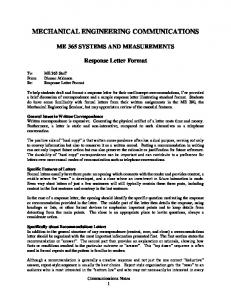
Figure 0.1 – Steps in sketching a circle
• Sketching straight lines (Bertoline et al., 2002) 1. 2. 3. 4. 5.
Orient the paper to a comfortable position. Do not fix the paper to the surface. Mark the end points of the lines to be sketched. Determine the most comfortable method for sketching lines, such as drawing from left to right. Use the edge of the paper as a reference point for making straight lines. Draw long lines by sketching a series of connected short lines.
• Sketching a circle or arc (Bertoline et al., 2002). Figure 0.1 1. Lightly mark the corners of a square with sides equal in length to the diameter of the circle or arc to be sketched. 2. Lightly sketch the square. 3. Mark the midpoints of the four sides of the square to give you four marks on the perimeter. 4. Sketch the circle by creating four short arcs, each between the marks on the perimeter. 5. Overdraw the arcs with a thicker line to complete the sketched circle. The degree of precision needed in a given sketch depends on its use. Quick sketches to supplement verbal descriptions may be rough and incomplete. Alternatively, sketches that convey important information should be drawn as accurately as possible, such as the toothbrush design in Figure 0.21 . Although sketches are not drawn to an exact scale, approximate proportionality of features should be maintained.
Dimensioning Dimensioning is the process of adding size information to a drawing. Dimensions can either indicate the size or the location of a feature. Dimensioning is governed by standards. The most widely used standard in the US is the American National Standards Institute ANSI Y14.5M-1982. Accurate and unambiguous dimensioning is very important for the effective and efficient communication of the design. An example of a dimensioned object is shown in Figure 0.3. Note the different types of lines types used. These include 1. Dimensions lines. Thin, solid lines with arrowheads on both ends. Arrowheads indicate the direction and extent of a dimension. Dimension lines are usually broken in the middle to place the dimension value. Alternatively, the dimension value can be placed above or below an unbroken line. 1 Puzak, N., Sunkara, A., DeRoche, R., and Rotthoff, C., “Redesigning an Electric Toothbrush”, final report for Introduction to Engineering Design course at Penn State, 2004.
2
Technical Sketching and Solid Modeling
Figure 0.2 – A more detailed sketch that may be part of an informal written report or oral presentation
2. Extension lines. Extend from an object line on a drawing to which a dimension refers, beyond the arrowhead of the dimension line. A gap of about 1.5 mm (1/16 in) should be left between the extension line and the object line. The extension line should extend about 3 mm (1/8 in) beyond the last arrowhead it touches. 3. Centerlines. Thin, alternating long and short dashes with about 1.5 mm (1/16) gaps in between. Centerlines are commonly used as extension lines for locating holes and other symmetrical features. When extended for dimensioning, centerlines cross over other lines without gaps. 4. Leader lines. Direct attention to a note or a dimension. Leader lines to circles or arcs should be radial so that if extended, they would pass through the center of the circular feature. To ensure accurate and unambiguous dimensioning, the following guidelines should be observed: 1. Use decimal numbers for dimensions values with the appropriate number of decimal places permitted by tolerance limits. For example, one decimal place would be used for a tolerance of ±0.1. 2. Avoid redundant dimensioning of features. A minimal set of dimensions should be used. 3. Place dimensions in the view that most clearly describes the feature being dimensioned. 4. A visible gap should be placed between the ends of the extension lines and the feature to which they refer. 5. Avoid placing dimensions within object boundaries. 6. Unless specified otherwise, angles are assumed to be 90o . 7. Avoid dimensioning hidden lines. 8. Specify diameters, radii, counterbored or countersunk holes with the appropriate symbol preceding the numerical value – R for radius, φ for diameter, V for countersunk hole, and U for counterbored holes. 9. Leader lines for diameter and radii should be radial lines. 10. The size and style of leader line, text, and arrows should be consistent throughout the drawing. 3
Figure 0.3 – Dimensioning example showing different line types
11. Display only the number of decimal places required for manufacturing precision. For example, if the units in the drawing are inches, a dimension of ‘3.31’ implies a desired manufacturing precision to one one hundredth of an inch.
Introductory Concepts in Solid Modeling Solid modeling supports the creation of parts, assemblies and automatic generation of the corresponding technical drawings. Solid modelers can provide a wide array of functions as listed in Table 0.1. The primary functions, indicated in bold in the table, are briefly discussed in the following sections. This description of solid modeling functions is intended to enhance the reader’s conceptual understanding of the functions rather than teach them how to use a specific software. The rational is that while the graphical user interface may differ from one solid modeler to another, the basic understanding behind feature creation does not. The assignments interspersed throughout the handout include references to the online tutorials found in the SolidWorks solid modeling package. The discussion is general, however, and applicable to any other package. The creation of parts occurs using a sequence of solid modeling functions to define the parts’ features. Features can be categorized as 1. Sketched features. Built from 2D profiles. 2. Operation features. Do not use sketches, but are directly applied to the part by selecting edges or faces. To use any solid modeling software package effectively, one must be familiar with the terminology. A summary of the common terms and their meaning follows. 1. Axis. An implied centerline that runs through every cylindrical feature. 2. Plane. A flat 2D surface on which 2D profile sketches are drawn. 4
Technical Sketching and Solid Modeling Table 0.1 – A comprehensive list of solid modeling functions. Adapted from Okudan and Rukowski (2004). Animation Assembling parts Complex blends Creation of draft angles Cross sections Dimensioning Extrusion File conversion facilities Isometric views Offset sections Polls Project directory Requirements capture Section views Sweeping profiles along curves Viewing and markup
Audit trail Associativity (one way, two way) Calendar and task management Creation and retention of ribs Decision making tools Document management Feature patterns (linear, circular) Filleting, chamfering/ blending Lofting Parametric relationships altering Product data management systems Rendering Revolve Shelling/skinning Threaded discussion Whiteboard
3. Origin. The point where the three default reference planes intersect. The coordinates of the origin are (x = 0, y = 0, z = 0). 4. Face. The surface or skin of a part. Faces can be flat or curved. 5. Edge. The boundary of a face. Edges can be straight or curved. 6. Vertex. The corner where edges meet. 7. Conventions. Commonly accepted methods or practices. The followings sections will describe several of the common solid modeling functions with the use of a simple example, the creation of a coffee cup.
Extrusion Extrusion, a sketched feature, requires sketching a 2D profile on a plane followed by extrusion of the sketch perpendicular to the plane. Figures 0.4 and 0.5 illustrate the first step in the solid modeling of a coffee cup: creation of a solid cylinder. First a 2D sketch of the cylinder profile is drawn (Figure 0.4) followed by extrusion of the profile to form a cylinder (Figure 0.5). The first feature created in a solid model is referred to as the base feature, to which all other features will be added. In this example, therefore, the extruded cylinder is referred to as the base feature. In general there are two types of extrusions: 1. Extrude boss (build). This feature adds material to the part and is what was used to create the base cylinder above.
Figure 0.4 – 2D sketched profile
Figure 0.5 – Extruded base feature (a cylinder) for coffee cup example
5
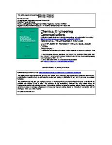
Figure 0.6 – Shelled coffee cup with specified wall thickness of 0.2 inches
Figure 0.7 – Coffee cup with filleted edges
2. Extrude cut. This feature removes material from the part. As such, it cannot be used to create the base feature. Both boss and cut features require 2D sketched profiles that must be attached to an existing part, unless a boss feature is being used to create a base feature. The following points should be noted during extrusion 1. While sketching 2D profiles, pay attention to the status of the sketch. A Sketch’s status can be • Under-defined. Additional dimensions or relations are required. • Fully-defined. No additional dimensions or relationships are required. A workable sketch must be fully-defined. • Over-defined. Contains conflicting dimensions and/or relations. 2. It is helpful to start a base feature with one of its vertices coinciding with the origin.
Shell Shell, in an operation feature, that removes material from a selected face of a solid object resulting in a hollowed interior. The shell feature requires specifying the wall thickness that is maintained throughout the hollowing process. For the coffee cup example one of the circular faces of the cylinder is selected, and a wall thickness of 0.2 inches specified as shown in Figure 0.6. The shell feature then hollows out the cylinder maintaining the 0.2 inch thickness along all the cylinder walls and at the circular base to create the coffee cup body. Note that the face that is selected before the shell feature is executed is left open after the operation.
Fillet Fillet is an operation feature used to round sharp edges and faces of a part either by removing or adding material (Figure 0.8). 1. Convex fillet. Applied to an outside edge and removes material. 2. Concave fillet. Applied to an inside edge and adds material. Both fillet features requires specifying a radius as shown in Figure 0.8. For the coffee cup example the sharp edges at the cup lip are rounded with fillets of 0.1 inch radius (Figure 0.7). Exercise 1 For all exercises, please save your models as they will be used in for multiple exercises 1. Complete Lesson 1: Parts, from the Solidworks on-line tutorial. Print out the final drawing.
6
Technical Sketching and Solid Modeling
Material removal R
Convex fillet feature showing material removal Material addition R
Concave fillet feature showing material addition
Figure 0.8 – Illustration of convex and concave fillets
2. Use the skills learned in the online tutorial to draw a solid model of a single light switch cover using the following steps: a) Measure a single or double light switch cover. b) Using paper and pencil, manually sketch the light switch cover. c) Dimension the sketch. d) Review the switch and determine the solid modeling functions needed to create the solid model. e) Create a simple single or double light switch cover solid model. Save the file as switchplate. f) Print your work. 3. What to turn in: Both printouts and the light switch cover sketch.
Assembling Parts An assembly is created when two or more components are put together or assembled to form a complex object. Mates are relationships that align and fit the components together. Changes made to the components affect the assembly, and conversely changes made to the assembly affect the components. The first component placed into an assembly in general is fixed. To move a fixed component, it must first be “unfixed.” Subsequent components brought into the assembly are translated, rotated and the relations that limit their movement established. The relations between components are created using the mates function, which aligns and fits together components in the assembly. Defining specific relations between faces, edges or vertices of the floating and fixed components creates relations that determine the relative location of components in an assembly and the relative motion between them. Relationships that can be defined include coincidence, concentric, parallel and vertical. Defined mates specify the movement in all six degrees of freedom (along and the X, Y and Z axes). An example of an assembly composed of six different parts is shown in Figure 0.9. Note that the four horizontal bars are the same, and therefore the same part is brought into the assembly four times. Exercise 2 1. Complete Lesson 2: Assemblies from the Solidworks on-line tutorial. 2. Using the light switch cover created in Exercises 1, design and model two screws to complete the assembly. The screws’ design should adhere to the following criteria: a) The screws must be longer than the thickness of the switchplate b) The screws must be 0.25 inches in diameter c) The head of the screws must be larger than the hole in the light switch cover
7
3. Create the light switch cover/screws complete assembly. Save the assembly file as switchplateassembly. 4. What to turn in: Print out of assembly from 1. and 3.
Creating Engineering Drawings from Solid Models Engineering drawings communicate size, shape and non-graphical information about the manufacturing processes such as drill, grind, heat treatment, etc. Engineering drawings are based on projection theory that determines how 3D objects are represented on 2D medium. Projection theory is based on two variables: line of sight and plane of projection. A line of sight (LOS) is an imaginary ray of light between an observer’s eye and an object. In parallel projection, all lines of sight are parallel. A plane of projection is an imaginary flat plane upon which the image created by the lines of sight is projected. Orthographic projection is a parallel projection technique in which the plane of projection is positioned between the observer and the object and is perpendicular to the parallel lines of sight. Orthographic projection can produce 1. Pictorial drawings that show three dimensions of an object in one view (Figure 0.10). 2. Multiview drawings that show only two dimensions of an object in a each view (Figure 0.11). MULTIVIEW DRAWINGS
In multiview drawings, six principal views are considered: front, top, left, right, bottom, and rear (back). Each principal view represents the image that would be seen through a side of a glass cube totally enclosing the object. Figure 0.11 shows the standard arrangement of all six views of an object in accordance with the ANSI standard third angle projection, which is commonly practiced in the US. Note that the top, front and bottom views must be aligned vertically, and the back, left, front, and right views must be aligned horizontally. The general characteristics of an object will determine which views are required to fully describe its shape. Typically, three standard views – front, top and right (or left) views – are used. For this case, the front and right (or left) view must be horizontally aligned, and the front and top views must be vertically aligned (Figure 0.12). Multiview drawings also require a title block (Figure 0.12). Information placed in the title block may include company name, part number, part name, drawing number, revision number, sheet size, drawing scale, material and finish, and the name of the person who completed or checked the drawing.
Figure 0.9 – Example of a magazine holder assembly composed of six different parts 8
Technical Sketching and Solid Modeling
Figure 0.10 – Pictorial drawings
Figure 0.11 – Layout for multiview drawings
The scale chosen to complete the drawing is indicated in the title block as a ratio. For example, for a full size drawing the scale will be indicated as 1:1, for a half size drawing the scale is 1:2. The ratio indicates the number of units on the drawing (first number) and the corresponding number of units on the object (second number). For reduction, scales of 1:2, 1:3, and 1:4 are common. For enlargement, scales of 2:1, 3:1, and 4:1 are typical. Finally, several different line types are used on engineering drawings as illustrated in Figure 0.13. These include 1. Visible or object lines. Used to represent features that can be seen in the current view. Solid lines are used for visible lines. 2. Hidden lines. Used to represent features that cannot be seen in the current view. Dashed lines are used for hidden lines. 3. Centerlines. Used to represent symmetry and paths of motion, and to mark the centers of circles. Centerlines are represented by 1 inch and 1/8 inch alternating long and short lines, respectively, with a 1/16 inch gap between. 4. Dimension and extension lines. Used in combination to indicate feature sizes and locations on a drawing. Exercise 3 1. Complete Lesson 3: Drawings from the Solidworks on-line tutorial. 2. The following exercise uses the drawing created in Question 1 of Exercise 1.
9
Figure 0.12 – An engineering drawing showing the title block
Figure 0.13 – Engineering drawing illustrating the different line types
10
Technical Sketching and Solid Modeling a) Create a new A-size ANSI standard drawing template. b) Create a drawing for Tutor2. Use the drawing template you created in the previous task. c) Create Front and Top views. Add an Isometric view. d) Import the dimensions from the part. e) Create a note on the drawing to label the wall thickness (Wall Thickness=4 mm). f) Save your file as tutor2drawing. 3. The following exercise uses the drawing created in Question 2 of Exercises 1, which was saved as switchplate. a) Create an engineering drawing of the single or double light switch cover. The drawing should show the front, top and right views as well as an appropriately filled title block. b) Imagine that the fillet feature is too small to be clearly seen and dimensioned. Insert a detail view to show the dimension of the fillet feature. c) Save the file as switchplatedetailview. 4. What to turn in: Print outs of all engineering drawings. Note that you should scale the text for all notations (example, your name, dimensions, scale, etc) so that they are of reasonable size within the drawing.
Section Views Section views use an imaginary cutting plane passing through the part to reveal interior features of an object that are not easily represented using hidden lines. Cutting plane lines, which show where the cutting plane passes through the object, represent the edge view of the cutting plane and are drawn in the view(s) adjacent to the section view. For example, the line A-A in the front view of the multiview drawing in Figure 0.14 indicates the location of the edge of the imaginary cutting plane used to generate section A-A. A horizontal section view is one where the cutting plane edge is in the front view and the top view is drawn as a section. Alternatively, a profile section view is one where the cutting plane edge is in the front and top views and the side view is drawn as a section. Multiple sections can appear on a single drawing. As shown in Figure 0.14, section lines or cross-hatch lines are added to a section view to indicate surfaces that are cut by the imaginary cutting plane. Different section line symbols can be used to represent various types of materials. However, the general-purpose section line symbol used in most section view drawings is that of cast iron. The cast iron section line is drawn at a 45o and spaced 1/16” (1.5mm) to 1/8” (3mm) or more depending on the size of the drawing, but can be changed when adjacent parts are in section. The spacing of section lines is equal or uniform on a section view. Section lines should be thinner than visible lines and should not run parallel or perpendicular to the visible outline. There are many different types of section views. Above, full sections were explained. However, there are times when it may be more appropriate to use a section view that is not a full section. For example, symmetrical objects can be sectioned using a half section. Or objects with only small areas that need to be clarified with the use of a section view can be represented with a broken-out section. Other types of section views are revolved sections, removed sections, offset sections and assembly sections. Exercise 4 1. Complete the Advanced Drawings Solidworks on-line tutorial. 2. What to turn in: Print out of final drawing.
Revolve The base feature created for the coffee cup can be created using another sketched feature: revolve. To complete a revolved base one needs to sketch a 2D profile and sketch a centerline or axis around which the 2D profile will be revolved. Angle of rotation should be specified. For the base of the coffee cup, the revolve feature is shown below.
Sweep This feature is created by moving a 2D profile along a path. A sweep feature is used to create the handle of the coffee cup. The sweep feature requires two sketches: (1) sweep path and 2) sweep section (profile). Some important rules to remember when creating a swept feature are 1. 2. 3. 4.
The The The The
sweep path is a set of sketched curves contained in a sketch, a curve, or a set of model edges. sweep profile must be a closed contour. start point of the path must lie on the plane of the sweep section. section, path or the resulting solid cannot be self-intersecting. 11
Figure 0.14 – Section view example
Figure 0.16 – Revolved Base Figure 0.15 – 2D Profile of Revolve
12
Technical Sketching and Solid Modeling
Figure 0.18 – Sweep Path Figure 0.19 – Completed Sweep Figure 0.17 – Sweep Profile
Exercise 5 1. Complete Revolves and Sweeps Solidworks on-line tutorial. 2. Design a candle to fit the candlestick. a) b) c) d)
Use a revolve feature as the base feature. Taper the bottom of the candle to fit into the candlestick. Use a sweep feature for the wick. Create a candlestick assembly.
3. What to turn in: Print out of final candle and candlestick assembly
Lofting The loft feature allows the blending of multiple profiles. A loft feature can be a base, boss or a cut. To create the loft feature, first the planes required for the profile sketches should be created. Then, a sketch should be completed on each plane. As an example, a version of the coffee cup base is created in the following steps (see Figure 0.20-0.23). 1. 2. 3. 4.
Determine the position of the planes relative to each other. Create the planes using the solid modeler. Draw the necessary 2D profile on each plane. Combine the sketched features using the loft function.
Exercise 6 1. Complete Lofts Solidworks on-line tutorial. 2. Create the bottle shown in Figure 0.24. All dimensions are in inches. 3. What to turn in: Print outs of the final drawings.
Chamfer The chamfer feature is very similar to a fillet feature in that it is applied to external or internal edges, and it can remove or add material. Unlike fillets which round an edge, however, the chamfer feature bevels the edge as shown in Figure 0.25. 13
Figure 0.20 – First plane
Figure 0.21 – Second plane
Figure 0.22 – Sketches on plane 1 and plane 2
Figure 0.23 – Lofted base
0.3
Working Drawings
Working drawings are the set of standardized drawings that are used to manufacture products. Through graphical and text information working drawings provide dimensions, form descriptions for all components, and specifications for the way the components are assembled. A complete set of working drawings for an assembly must include (1) detail drawings of each non-standard part2 and (2) an assembly drawing that shows all the standard and nonstandard parts in relation to how they will all fit together to form the final assembly. The assembly drawing can be shown as an exploded view (Figure 0.26) or an unexploded view (Figure 0.27). An assembly drawing should contain all of the following elements (Bertoline et al., 1998): 1. All the parts, drawn in their operating position. 2. The bill of materials (BOM). With reference to Figures 0.26 and 0.27, BOM is a table in the assembly drawing that contains detail (identification) number for each part, the quantity of the part needed for a single assembly, the name of the part, and if necessary, a description of the part. Detail numbers are typically composed of a string of numbers and letters. In Figure 0.26, the parts are numbered sequentially from MP-001 to MP-006. 3. Leader lines with balloons assigning a detail number to each part. 4. If required, leader lines with balloons pointing to areas or features of parts that require particular machining and assembly operations, or that indicate critical dimensions for these functions. A detail drawing is a dimensioned, multiview drawing of a single part that describes the form, size and material in sufficient detail for the part to be manufactured (Bertoline et al., 1998). ANSI standards are 2 Non-standard
14
parts are those that are not commercially available and must be manufactured for the current application.
Working Drawings
Figure 0.24 – Bottle dimensions for Exercise 6
followed when producing detail drawings. The detail drawings for the phone book holder assembly presented in Figure 0.26 are shown in Figures 0.28 to 0.333 . As previously noted, detail drawings of standard parts are not drawn, however, they are listed in the bill of materials for the assembly. A standard part in this context can be considered to be any part that is purchased from suppliers and used without any modifications in the assembly. Working drawings are numbered using a standard numbering system established by company guidelines. These guidelines in general allow for drawing revisions to be tracked in databases. For example, in the title block of Figure 0.26, the drawing number is MP-008 with a revision number of 01. In this case, the drawing number can be tracked as MP-008-01 or MP-008R01. If the drawing were revised, the second and third revisions would be numbered MP-008-02 and MP-008-03, respectively. Exercise 7 1. Complete the Assembly mates Solidworks on-line Tutorial (nothing to turn in). 2. Complete the Bill of Materials Solidworks on-line Tutorial. Turn in a print-out.
References Bertoline,G.R., Wiebe, E.N. and Miller, C.L., “Fundamentals of Graphics Communication”, 3nd Edition, New York: McGraw-Hill, 2002. 3 Based on a phone book holder designed as a class project during the Introduction to Engineering Design course at Penn State by Amro Asad, Geoffrey Geise, Bryce Lambert, Garrett Risberg and Patrick Woolcock.
15
Figure 0.25 – Object showing chamfered edges
Figure 0.26 – Exploded assembly drawing of a phone book holder
16
Working Drawings
Figure 0.27 – Unexploded assembly drawing of a phone book holder
Figure 0.28 – Detail drawing of left side panel
17
Figure 0.29 – Detail drawing of right side panel
Figure 0.30 – Detail drawing of bottom panel
18
Working Drawings
Figure 0.31 – Detail drawing of back panel
Figure 0.32 – Detail drawing of front panel
19
Figure 0.33 – Detail drawing of bars
Nam, T.J. and Wright, D., “The Development and Evaluation of Syco3D: A Real-Time Collaborative 3D CAD System”, Design Studies, vol. 22, pp. 557-582, 2001. Requicha, A.A.G. “Mathematical Models of Rigid Solids: Theory, Methods and Systems”, ACM Computing Surveys, vol. 12 no. 4, pp. 437-464, 1980. Requicha, A.A.G. and Voelcker, H.B., “An Introduction to Geometric Modeling and Its Applications in Mechanical Design and Production”, In Advances in Information Systems Science, Ed. J.T.Tou, Vol.8, Plenum Publishing, 1981. Requicha, A.A.G. and Voelcker, H.B., “Solid Modeling: A Historical Summary and Contemporary Assessment”, IEEE Computer Graphics and Applications, pp. 9-24, 1982. Requicha, A.A.G. and Voelcker, H.B., “Solid Modeling: Current Status and Research Directions”, IEEE Computer Graphics and Applications, 1983. Voelcker, H.B. and Requicha, A.A.G., “Research in solid modeling at the University of Rochester: 1972-1987”, in Fundamental Developments of Computer-Aided Geometric Modeling, L. Piegl (Ed.), London: Academic Press Ltd., pp. 203-254, 1993. Schmitz, B., Tools for innovation, Industry Week, May 15th, 2000. Tovey, M. and Owen, J. “Sketching and Direct CAD Modeling in Automotive Design”, Design Studies, vol. 21, pp. 569-588, 2000. Shapiro, V. “Solid Modeling”, In Handbook of Computer Aided Geometric Design, Eds. G.Farin, J. Hosheck, MS. Kim, Elsevier Science Publishers, 2002. Li, G., Jinn, J.T., Wu, W.T., and Oh, S.I., “Recent Development and Applications of Three-Dimensional Finite Element Modeling in Bulk Forming Processes”, Journal of Materials Processing Technology, 113 (1-3), pp. 40-45, 2001. Green, R., “CAD Manager Survey - Part 2”. CADALYST, 20(12), pp. 26-27, 2003. Rossignac, J. and Requicha, A.A.G., “Solid Modeling”, In the Encyclopedia of Electrical and Electronics Engineering, Ed. J. Webster, New York:John Wiley and Sons, 1999. Ullman, D.G. “Toward the Ideal Mechanical Engineering Design Support System”, Research in Engineering Design, 2001.
20