2) Negligible pressure and heat losses/gains in the pipe net- works or system components. 3) Isenthalpic expansion across expansion valves. 4) The dead state ...
Volume : 2 | Issue : 5 | May 2013 • ISSN No 2277 - 8179
Theoretical Aspect of Thermodynamic analysis of Cascade Refrigeration System: A Review B. J. Bhardia S. R. Sunasara J. J. Makadia
ABSTRACT
Research Paper
Engineering KEYWORDS :
Mechanical Engineering Department, RK University, Kasturbadham, Rajkot-Bhavngar highway, Rajkot, Gujrat, India Mechanical Engineering Department, RK University, Kasturbadham, Rajkot-Bhavngar highway, Rajkot, Gujrat, India Mechanical Engineering Department, RK University, Kasturbadham, Rajkot-Bhavngar highway, Rajkot, Gujrat, India
This paper describes review study about thermodynamic analysis of a cascade refrigeration system using carbon dioxide and ammonia as working fluid in law and high temperature sides. The effect of operation parameters, such as the evaporating temperature, the condensing temperature, temperature difference in cascade Condenser and superheat degree, on the system performance was investigated and those parameters are greatly affected on the system.
1. Introduction In low-temperature applications, the required evaporating temperature of the refrigeration system ranges from -40oC to -55oC, so a single-stage vapour-compression refrigeration system is insufficient. Instead, two-stage or cascade refrigeration systems are used for low-temperature applications. The two stage refrigeration require higher input energy as per same capacity the cascade refrigeration which includes separate two cycle with different two refrigerant. The natural refrigerants such as air, water, ammonia, carbon dioxide and hydrocarbons, have recently received increased attention due to the environmental concerns of global warming and emerging regulations. It was shown that carbon dioxide is the most promising natural refrigerant across a broad spectrum of automotive, domestic, commercial and industrial refrigeration and air-conditioning systems[1]and Ammonia (R717) is a natural refrigerant that is most commonly adopted in low-temperature two-stage refrigeration systems, but it has disadvantages. For instance, ammonia has a pungent smell; it is toxic and moderately flammable, and has relatively large swept volume requirements at under -35OC [2]. Many studies have been conducted on the NH3/CO2 cascade refrigeration system to investigate the system performance.
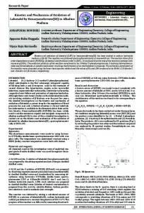
2. Cascade System Description A two-stage cascade system employs two vapour-compression units working separately with different refrigerants and interconnected in such a way that the evaporator of one system is used to serve as condenser to a lower temperature system (i.e., the evaporator from the first unit cools the condenser of the second unit).
A schematic diagram of cascade refrigeration system shown in Figure 1, the condenser of HT system, called the first or high pressure stage, is usually fan cooled by the ambient air. In some cases a water supply may be used, but air cooling is much more common. The evaporator of HT system is used to cool the condenser of LT system called the second or low-pressure stage. The unit that makes up the evaporator of HT system and the condenser of LT system is often referred to as the inter-stage or cascade condenser.
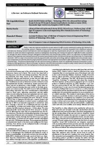
Fig. 1 : Schematic diagram of cascade refrigeration[4]. Figure 2 and 3 shows the T–s and P–h diagram of cascade refrigeration system, respectively. The condenser in this cascade refrigeration system rejects a heat of QC from the condenser at condensing temperature of TC, to its warm coolant or environment at temperature of T0. The evaporator of this cascade system absorbs a refrigerated load QE from the cold refrigerated space at evaporating temperature TE. The heat rejected by condenser of LT system equals the heat absorbed by the evaporator of the HT system. TCS and TES represent the condensing and evaporating temperatures of the cascade condenser, respectively.
Fig. 2 : T-S Diagram of cascade refrigeration system[4] 194
IJSR - INTERNATIONAL JOURNAL OF SCIENTIFIC RESEARCH
Research Paper
Volume : 2 | Issue : 5 | May 2013 • ISSN No 2277 - 8179
The capacity of the evaporator is defined as:
5)
Compressor isentropic efficiency for low-temperature circuit is given as:
6) Whereas, for high-temperature circuit is given as:
7)
Compressor power consumption for low-temperature circuit is given as:
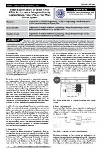
Fig. 3 : P-V Diagram of cascade refrigeration system[4] Approach represents the difference between the condensing temperature of LT system and the evaporating temperature of HT system. The evaporating temperature (TE), the condensing temperature (TC), cascade condensing temperature (TCS) and the temperature difference in the cascade condenser (∆TCC) are four important parameters of a cascade refrigeration system.
As stated earlier, cascade systems generally use two different refrigerants (i.e., one in each stage). One type is used for the low stage and a different one for the high stage. The reason why two refrigeration systems are used is that a single system cannot economically achieve the high compression ratios necessary to obtain the proper evaporating and condensing temperatures[4].
3.Thermodynamic Analysis : A parametric study with fixed cooling capacity, and various condensing temperature, evaporating temperature and temperature difference in the cascade-condenser must be conducted to determine the optimum temperature of a cascade-condenser in a cascade refrigeration system operated at low temperature. The condensing temperatures used in the parametric study are 35oC, 40oC and 45oC. The evaporating temperatures are -45oC, -50oC and -55oC. The temperature differences in the cascade condenser are regarded as 3oC, 4oC and 5oC.[4]
Assumptions: 1) Cascade condenser effectiveness with isentropic efficiency for both high and low-temperature compressors is assumed to be 80%. 2) Negligible pressure and heat losses/gains in the pipe networks or system components. 3) Isenthalpic expansion across expansion valves. 4) The dead state (ambient) conditions are 25 0C and 1 atm. 5) The mass flow rate for the lower system region is 0.2 kg/ min. Based on the assumptions described above, the four balance equations are : Mass balance:
1)
Energy balance:
2) Exergy balance:
Entropy Balance:
8)
Whereas, for high-temperature circuit, it is given as:
9)
Total work done or Actual work done:
10)
11)
12)
The rate of heat transfer in the cascade condenser is determined from: From the above Eq. (3.10) the mass flow ratio is derived as:
The rate of heat rejection by the air-cooled condenser is given as:
13) The overall COP of the system is determined as:
The reversible work is the work for ideal Carnot system.
14)
15) The reversible work would be express as
16)
Exergetic efficiency or Second law efficiency is given by
17)
3.1 Parametric Study: The equations of the mathematical model reveal that the systems COP, exergetic efficiency and exergy destruction can be expressed as functions of nine operating parameters.
3)
4)
IJSR - INTERNATIONAL JOURNAL OF SCIENTIFIC RESEARCH
195
Volume : 2 | Issue : 5 | May 2013 • ISSN No 2277 - 8179
Table:1 : Parameter Range : Parameters
Evaporating temperature Condensing temperature
Range :
TE = - 85 0C to - 0 0C at intervals of 5 0C TC = 25 0C to 50 0C at intervals of 5 0C
Cascade condenser TCS = - 55 0C to 0 0C at temperature intervals of 5 0C Temperature difference in the cascade condenser ∆TCC = 2 0C to 10 0C, at intervals of 2 0C Subcooling (in HT and LT system) ∆Tsub = 2 0C to 10 0C at Superheating (in HT and LT intervals of 2 0C system) ∆Tsup = 2 0C to 10 0C at Isentropic efficiency (LT intervals of 2 0C compressor) = 65% to 100% at intervals Isentropic efficiency (HT of 5% compressor = 65% to 100% at intervals Cascade condenser efficiency of 5% = 65% to 100% at intervals of 5%
4. System COP and exergetic efficiency : To evaluate the influences of the operating parameters on both the system’s COP and exergetic efficiency, a statistical procedure has been used to analyse the parametric study results obtained considering the range of values indicated in table: 1. This procedure is the Anova Multifactorial [5] the system’s COP and exergetic efficiency average values and the ranges of values resulting from the parametric studies for each one of the evaluated parameters. Therefore, it will be show the maximum and minimum values of the COP and exergetic efficiency for the entire region analysed, as well as their average value for each parameter when varying all others simultaneously. Thus, the results and conclusions obtained from this analysis have applicability over the entire region studied.[8] Evaporating temperature has to be as high as possible in order to obtain the highest COP. This temperature depends on the environmental temperature that has to be cooled and the difference between temperatures established as a design parameter in the evaporator. Condensing temperature has to be as low as possible to increase the COP to the maximum. On the other hand, the NH3 temperature established as a design parameter of the condenser. As for temperature differences in the cascade exchanger, ∆TCC, results always show that for a lower ∆TCC a higher COP is obtained. optimum condensing temperature does not present a continuous trend. [6]
REFERENCE
Research Paper Optimum temperature value could be established as function depending only on the CO2. As a result the maximum COP value is set as a function of the established parameters. The optimum values for Tc evaporating temperature, NH3 and maximum COP as a function of CO2 condensing temperature and the ∆TCC temperature differences, can be determined statistic in ∆TCC and COP respectively. TE & TC which can be replaced by the cooled environment temperature and the condensed environment temperature, respectively[7].
4.1. Exergy losses: To evaluate the exergy losses of each system’s components and the exergy loss rate of the whole system, a parametric study was applied at prototype specified design conditions It can be appreciated that the highest exergy loss rate occurs at the lowest CO2 condensing temperature condensing temperature, and decreasing trends are present in all the NH3 system’s components. In the CO2 throttle and the cascade heat exchanger present an increasing tendency with Tc increments. In some of the system’s components, the exergy loss rate increases whilst in others the exergy loss rate decreases with Tc increments. This behaviour has been observed after evaluating the whole system Therefore, an optimum value of TC is found.[4,6,9]
5. Conclusions This work studies the analysis of the various parameters of design and operation of a CO2/NH3 cascade refrigeration system and their influences over the system’s COP and exergetic efficiency is generated. The analysis was carried out based on a general mathematical model that was prepared by found in the literature. The system’s COP and exergetic efficiency can be expressed as functions of six design/operating parameters. A statistical procedure has been used to analyse the parametric study results obtained. The analysis reveals that all the evaluated parameters have a statistically significant effect and should be taken into account.
From Literature the results show that the COP increases 70% when the T varies from 55oC to 30oC. As T increases, the other parameters on the COP also increase. The COP increases from 25o to 50oC. The system COP decrease by 9% when DT varies from 3o to 6o C. The exergetic efficiency decreases around 45% and 9% with the increases. The CO2 optimum condensing temperature value increases when CO2 evaporating and/or NH condensing temperatures increase.
Acknowledgement: It is gratefully acknowledged that the work presented in thispaper has been greatly supported by Mr. Jiten Makadia and S.R. Sunasara
[1] Bansal, P.K., Jain, S., 2007. Cascade systems: past, present, and future. ASHRAE Trans. 113 (1), 245–252. | [2] A. Person, New developments in industrial refrigeration, ASHRAE Journal 43 (2001) 54e58. | [3] Getu, H.M., Bansal, P.K., 2008. Thermodynamic analysis of and R744–R717 cascade refrigeration system. Int. J. Refrigeration 31 (1), 45–54. | [4] P.K.Kutte, Thermodynamic analysis of cascade refrigeration system, refrigerant, 2003 International Congress of Refrigeration, 2010. | [5] S. Sawalha, A. Suleymani, J. Rogstam, CO2 in permarket refrigeration, CO Project Report Phase I, KTH Energy Technology, 2006. Available from: . | [6] W. Mendenhall, T. Sincich, Statistics for Engineering and the Sciences, Prentice-Hall, Englewood Cliffs, NJ, 1995. air conditioner, Applied Thermal Engineering 21 (2001) 871–880. | [7] A. Rozhentsev, W. Chi-Chuan, Some design features of a CO2 air conditioner, Applied Thermal Engineering 21 (2001) 871–880. | [8] S. Zha, Y. Ma, J. Wang, M. Li, The thermodynamic analysis and comparison on natural refrigerants cascade refrigeration cycle, Fifth IIR-Gustav Lorentzen Conference on Natural Working Fluids at Guangzhou, IIR, 2002. | [9] T.S. Lee, C.H. Liu, T.W. Chen, Thermodynamic analysis of optimum condensing temperature of cascade condenser for CO/NH cascade refrigeration systems, in: IIR Ammonia Refrigeration Conference, Ohrid, Republic of Macedonia, 2005.
196
IJSR - INTERNATIONAL JOURNAL OF SCIENTIFIC RESEARCH