Engineering Ambient Intelligence Systems using Agent Technology Nikolaos Spanoudakis, IEEE Senior Member Applied Mathematics and Computers Laboratory (AMCL), Technical University of Crete Chania, Greece
[email protected]
Pavlos Moraitis Laboratory of Informatics Paris Descartes (LIPADE), Paris Descartes University Paris, France
[email protected] Abstract—This paper shows how to model and implement an Ambient Intelligence (AmI) System using agent technology. The HERA project, undertaken by a consortium with members from the academia as well as the industry, applied the Agent Systems Engineering Methodology (ASEME), an agent-oriented software engineering methodology, to develop a real world system for the ambient assisted living application domain. This paper focuses in presenting the software architecture, along with the development method and validation results. The obtained results demonstrate the added value of agent technology use, along with how ASEME can be applied for modeling a real-world AmI system. Keywords: D.2.10.f Methodologies, D.2.11 Software Architectures, J.8.h Health care, I.2.11.b Intelligent agents, I.2.11.d Multiagent systems
1. Introduction This paper is concerned with addressing the non-trivial task [1] of engineering an Ambient Assisted Living (AAL) information system using Agent Technology. AAL systems combine the application domains of Ambient Intelligence (AmI) and home based eHealth. AmI refers to environments empowered with computing capability that deliver services and applications to people. Autonomy, distribution, adaptation and responsiveness, are key characteristics of the AmI computing components [2]. The HERA project (w3.mi.parisdescartes.fr/hera), co-funded by the AAL Joint Programme (www.aal-europe.eu), built an AAL system to provide cost-effective specialized assisted living services for the elderly people suffering from Mild Cognitive Impairment (MCI), mild/moderate Alzheimer’s Disease (AD), or other diseases (diabetes, cardiovascular) with identified risk factors, aiming to significantly improve the quality of their home life and extend its duration. To address their needs, HERA provided the following main categories of services:
Cognitive Exercises: the users play cognitive reinforcement games Passive communication: the user can select (or receive a pro-active suggestion) to watch informative videos and news items related to his/her disease Pill and Exercise reminders Reality orientation: date and time is visible on screen Blood pressure and weight monitoring
In HERA, we used a combined agent- and service-oriented software development approach. The use of the TV set and remote control for Human-Machine Interaction allowed for a quick learning curve for our users. We used a service oriented architecture based on web services that allowed the different sub-systems to be connected in a plug and play standardized way. In this paper we focus in presenting how we built the intelligent part of the HERA system using an Agent Oriented Software Engineering (AOSE) methodology, the Agent Systems Engineering MEthodology (ASEME, www.amcl.tuc.gr/aseme). AOSE is concerned with defining metaphors, concepts and methods for defining agent-based systems. Such systems (called also multi-agent systems) are based on the interaction of different entities called agents, a specific type of software, that is:
proactive (has goals and pursues them on its own),
reactive (respond to events in its environment) social (is acquainted with other similar software and can cooperate-compete with it), autonomous (does not need human intervention to act), and, intelligent (may perform tasks that when performed by humans we consider that are the evidence of a certain intelligence).
These characteristics address the ambient intelligence requirements and motivated us in using agent technology for the HERA project. In the next section we provide some background on ASEME and then we present the system development process. Section four presents the system evaluation results and section five concludes.
2. The Agent Systems Engineering Methodology (ASEME) Agents are computational entities that can have a number of capabilities such as sensing, decision making, planning, learning, etc. These capabilities interact through what we call the intra-agent control in different ways to define diverse kinds of behavior. In the context of multi-agent systems, several agents can interact by using different kinds of protocols, which implement various types of interactions (e.g. negotiation, deliberation, persuasion, etc). These protocols implement what we call the inter-agent control. Agent Oriented Software Engineering (AOSE) methodologies are software engineering methodologies adapted to the particular characteristics of agents as individual entities, but also of multi-agent systems corresponding to communities of agents. ASEME combines successful concepts from the AOSE domain with the model-driven engineering (MDE) paradigm. In MDE models guide the development process and are systematically transformed to system implementations. According to this approach, the models of each software development phase (i.e. analysis, design or implementation) are produced by applying transformation rules to the models of the previous phase. Successive models add more detail and become more formal, gradually leading to implementation. ASEME, uniquely among other AOSE methodologies, caters for the integration of the inter-agent control model to the intraagent control model. The first defines the protocols that govern the coordination of the society of the agents, while the latter defines the agent’s behavior by coordinating the different modules that implement his capabilities. ASEME uses a Domain Specific Language, the Agent Modeling Language (AMOLA), which provides the syntax and semantics for creating models of multi-agent systems covering the analysis and design phases of a software development process. Another novelty of ASEME is the definition of three levels of abstraction for each development phase. The first is the societal level. There, the whole multi-agent system functionality is modeled. Then, the agent level zooms in each part of the society, i.e. the agent. Finally, the details that compose each of the agent’s parts are defined in the capability level. In Figure 1, the ASEME phases, the different levels of abstraction and the AMOLA models related to each one of them are presented. We aim to show that agent technology (and ASEME) is useful for modeling real world AAL intelligent systems where intelligence, autonomy and proactiveness are necessary features. The system validation process that we followed in HERA helped to identify and measure the added value of the use of our approach.
Development Phase Requirements Analysis
Society Level
Levels of Abstraction Agent Level
Capability Level
Actors
Goals
Requirements
Analysis
Roles and Protocols
Capabilities
Functionality
Design
Society Control
Agent Control
Components
Implementation
Platform management code
Agent code
Capabilities code
Figure 1. ASEME, the phases and abstraction layers
3. The HERA Software Engineering Process In this section, we present the ASEME process in a step-by-step manner, as it was followed for the HERA project, for developing the Multi-Agent System (MAS) module. The process was incremental, as the HERA system deployment took place in
two major phases. Firstly, it was deployed in the medical center’s premises for evaluation by the medical personnel and for controlled interaction with the patients and, secondly, it was deployed inside the users’ homes for final evaluation. The main user groups for the HERA system were the end-users (elderly over the age of 65, suffering from Mild AD, Moderate AD, or MCI) and the medical personnel.
Requirements Analysis Phase In the requirements analysis phase, AMOLA defines the System Actors and Goals (SAG) model, which is similar to the Tropos actor diagram [3], containing the actors and their goals. Requirements are associated with goals in free text. In HERA, we identified a personal assistant (PA) actor that serves a specific user and has access to the user’s profile data. This actor is proactive in the sense that it is always active following the user’s agenda and providing support and advice by taking action whenever needed. For example, it is able to send a message to the user for reminding him to take his pills and to receive sensor information about the user. Moreover, the PA uses the requests’ history in order to adapt the services to the user’s habitual patterns. We also have an interface actor that acts as a gateway to the PAs. Thus, while the PA accesses itself all information sources that it needs, the HERA backoffice sends information to the MAS through the interface actor; see, e.g., the AssignPills goal of the PA, which is dependent on the Interface, in Figure 2(a), thus there is a directed line from the depender (PA) to the goal and then from the goal to the dependee (Interface).
Analysis Phase In this phase the requirements are transformed to technical needs. Towards this end, AMOLA defines: a) the System Use Cases model (SUC) for decomposing goals to generic activities, a model quite similar to the Unified Modeling Language (UML) use case diagram, b) the Agent Interaction Protocol model (AIP) for defining the protocols that govern inter-agent interactions, and, c) the System Roles Model (SRM), inspired from the Gaia methodology [4], for defining the process of a single role realizing zero or more interaction protocols. The first task of this phase is to define the System Use Case (SUC) model. This model is initialized by a transformation of the requirements phase SAG model to a SUC model, where SAG actors are transformed to SUC roles (depicted as the UML Use Case diagrams roles) and SAG goals to SUC use cases (depicted as the UML Use Case diagrams use cases). The analyst refines the SUC model by decomposing high level tasks to more simple activities using the, familiar from UML, «include» relationship. Figure 2(b) shows the automated transformation process from the SAG model to a SUC model and the AssignPills use case, which has been decomposed to several use cases (using the «includes» relationship), three of which are connected to the Interface role and the other two to the PersonalAssistant role. Then, the Agent Interaction Protocols (AIP) model is constructed. The AIP model focuses on the different roles’ joint use cases; thus, all the use cases that have more than one participant define an AIP model instance. Each protocol defines the participating roles, the rules for engaging, the expected outcomes and the process that each participant follows within the protocol. Figure 3(a) shows the AssignPills use case modeled as an Agent Interaction Protocol. The AIP model contains in a yellow box the protocol name, connected to as many pink boxes as there are participants. Each pink box contains four bullets that contain (from top to bottom):
The participant role’s name The preconditions that must hold so that the participant role can enter the protocol (in free text format) The postconditions that must hold when the participant role exits the protocol (in free text format) An expression describing the process followed by the participant role within the protocol
The process is defined formally using liveness operators for connecting activities. Briefly, A.B means that activity B is executed after activity A executes, A* means that A is executed zero or more times, A+ means that A is executed one or more times, A~ means that A is executed indefinitely (it resumes as soon as it finishes (it is the equivalent to the ω operator in the original Gaia formalism), A|B means that either A or B is executed exclusively, A||B means that A and B are executed concurrently, and [A] means that A may or may not be executed.
(a)
(b)
Figure 2. A portion of the SAG model (a) and of the SUC model (b). In the SUC diagram the AssignPills use case has been analyzed to several included Use Cases
(a)
(b) Figure 3. The AssignPills Agent Interaction Protocol model (a) and its transformation to an intEr-Agent Control model (b)
Thus, the AssignPills protocol has two participant roles (i.e. Interface and PersonalAssistant). Taking a closer look to their process fields the reader can find that:
The Interface waits for a new pill assignment to be submitted (using the WaitForNewPill PrescriptionService activity). When the service is invoked it determines the relevant PA (using the SelectTargetPAAgent activity) and sends an appropriate request message (using the SendNewPillPrescriptionRequest activity) The PersonalAssistant waits to receive such a message (using the ReceiveNewPillPrescriptionRequest activity) and updates its user’s schedule accordingly (using the UpdateUserSchedule activity)
Subsequently, the SUC and AIP models are transformed to SRM models. We build one SRM for each role that will be developed as an agent (analyst’s choice). In the SRM we use liveness formulas [4] for defining the agent capabilities and connecting them with each other to define the overall role’s process. Liveness formulas have a name on their left hand side (representing a capability) and an expression built using the liveness operators on the right hand side. Figure 4 presents the SRM model for the Personal Assistant (PA) role. It includes the role’s name, capabilities, activities and the liveness formulas. The top formula has the role name on the left-hand side and an expression on the right-hand side. Thus, the PA role process is the following: firstly it executes the PersistRegisterBehaviour activity, optionally followed by the PersistLoaderBehaviour activity. Then the StoreAgentState, AssignExercises, AssignPills, UserSwitched- OnTV, and, UpdateUserProfile capabilities are executed in parallel and if they finish they are restarted. In the next formulas these capabilities are further refined.
Role: Personal Assistant Capabilities: StoreAgentState, UserSwitchedOnTV, UpdateUserSchedule, ResolveConflicts, UpdateUserProfile, RemindUser, RemindUserOfTask, GetFeedbackOnUserAction, LearnUserHabits, AssignPills, AssignExercises Activities: PersistRegisterBehaviour, PersistLoaderBehaviour, WaitForMidnight, AutoSaveBehaviour, ReceiveUserSwitchedOnTVInform, UpdateUserProfileStructure, InvokeAvailableVideosInformService, UpdateUserScheduleStructure, CheckIfConflictsExist, ReasonOnItemsPriorities, SortItems, ReceiveUserProfileUpdateRequest, WaitForUserScheduleNextItem, InvokeBloodPressureModule, ReasonOnPillsQuantity, InvokeNotificationModule, ReceiveUserActionInform, SelectNewDate, ReasonOnUserAction, ReceiveNewPillPrescriptionRequest, ReceiveNewExercisePrescriptionRequest Liveness: PersonalAssistant = PersistRegisterBehaviour. [PersistLoaderBehaviour]. (StoreAgentState~ || AssignExercises ~ || AssignPills ~ || UserSwitchedOnTV~ || RemindUser~ || UpdateUserProfile~) StoreAgentState = WaitForMidnight. AutoSaveBehaviour UserSwitchedOnTV = ReceiveUserSwitchedOnTVInform. UpdateUserProfileStructure. [InvokeAvailableVideosInformService. UpdateUserSchedule] UpdateUserSchedule = ResolveConflicts. UpdateUserScheduleStructure ResolveConflicts = (CheckIfConflictsExist. ReasonOnItemsPriorities. SortItems)+ UpdateUserProfile = ReceiveUserProfileUpdateRequest. UpdateUserProfileStructure RemindUser = WaitForUserScheduleNextItem. [InvokeBloodPressureModule. ReasonOnPillsQuantity]. RemindUserOfTask RemindUserOfTask = InvokeNotificationModule. GetFeedbackOnUserAction. LearnUserHabits GetFeedbackOnUserAction = ReceiveUserActionInform. [SelectNewDate. UpdateUserSchedule] LearnUserHabits = ReasonOnUserAction. [UpdateUserSchedule] AssignPills = ReceiveNewPillPrescriptionRequest. UpdateUserSchedule AssignExercises = ReceiveNewExercisePrescriptionRequest. UpdateUserSchedule
Figure 4. The PersonalAssistant (PA) role SRM model. The liveness property contains the formulas Having defined the SRM for the PA and the Interface roles, the next task of the ASEME process is to define the functionality of each activity. Functionality refers to the single tool, algorithm or method that will realize the activity. If this is not possible, then the activities need to be further decomposed so that each corresponds to a single functionality.
Design Phase In the design phase AMOLA defines the Inter-Agent Control (EAC) model and the Intra-Agent Control (IAC) model, which are based in the language of statecharts [5]. The model associated to the first abstraction level of this phase is the inter-agent control, which defines interaction protocols. The implementation of the inter-agent control is done at the agent level via the capabilities and their appropriate interaction, which is defined via the intra-agent control. Finally, in the third level each capability is defined with regard to its functionalities. This task includes identifying the underlying technology or software libraries, and defining the relevant data structures and algorithms. The EAC and IAC models are initialized by transforming the AIP and SRM models to EAC and IAC models respectively. The liveness2statechart ASEME transformation tool employs a recursive algorithm, which takes as input a set of liveness formulas and applies operator transformation templates to build the statechart. Then, the user edits the variables and the transition expressions of the statechart.
The automatically generated EAC model by the AssignPills AIP model is presented in Figure 3(b). Statecharts [5] are formal models that describe complex processes and control structures using directed graphs with nodes (states) and edges (transitions) and are edited using the Kouretes Statecharts Editor tool (KSE, www.kouretes.gr/KSE). Six types of states are allowed: or-states (drawn as yellow-color-labeled rounded rectangles), indicating complex states with mutually exclusive sub-states (only one substate is executed at each time), start-states (bold black dots), indicating the entry of execution in an or-state, end-states (circled black dots), indicating the end of execution of an or-state, and-states (blue-color-labeled rounded rectangles), indicating states with sub-states of type or which are executed concurrently, basic-states (green-colored rounded rectangles), indicating the execution of base activities, and condition-states (drawn by a circled “c”), providing the ability to make conditional transitions. Each transition from one state (source) to another (target) has an expression whose syntax follows the pattern e[c]/a, where e is the event triggering the transition, c is the condition that needs to be satisfied for the transition to take place when e occurs, and a is an action executed when the transition is taken. All the elements of an expression are optional. The two participating roles in the EAC model in Figure 3(b) are transformed to orthogonal components (the or-states included in the and-state) of the statechart. The reader can easily observe that the activities connected with the ”.” operator are transformed to states that one follows the other with a start-state before the first and an end-state after the last. The designer can now edit the transition expressions to complete the EAC model for each protocol. The items that the designer can use for defining the state transition expressions are the message performatives (i.e. the types of the messages), the ontology for defining the messages content, and, timers [6]. In HERA, at this point we defined the web services that the MAS would expose and the web services that it would need to invoke, thus connecting the MAS module to the general service oriented architecture. The next step was to transform the formulas of the SRM models to IAC models. The instantiation of the statechart was again automatic. Again, the modeler defines the transition expressions not already defined in the EAC model.
Implementation Phase During the implementation phase the IAC models are transformed to source code by the ASEME code generation tool for the popular Java Agent Development Framework (JADE, jade.tilab.com). This transformation is automatic and the programmers do not worry about the definition of the agents or the scheduling of the tasks [6]. They are mainly focused to implementing the code corresponding to the basic-states, i.e. connecting them to the functionalities using specific technologies. The software architecture for the HERA MAS module is presented in Figure 5. It was deployed in a Linux virtual machine in the Paris Descartes University (PDU) cloud and employed a number of technologies.
JADE 4.0 Java 6
Gorgias
AKB
JPL
JADE API
Persistence add-on
WSIG add-on
HERA MAS
SWIProlog
Web services Apache Tomcat
Hibernate
HSQL
Persistence service
Linux Debian VM PDU Cloud Services
Figure 5. Server Deployment Scheme The Apache tomcat web server (tomcat.apache.org) was used for deploying the web services of the HERA agent platform. The WSIG (Web Service Integration Gateway) JADE add-on handled the part of receiving a web service request from Apache and making it available to the agents in the form of an Agent Communication Language (ACL) message. The Persistence add-on of JADE allowed for persisting the state of agents (recover user profiles and learned data in the case that the system crashes) using the HSQL relational database (hsqldb.org) via Hibernate (a tool that facilitates the storage and retrieval of Java domain objects via Object/Relational Mapping, hibernate.org), which was used for automating the transformation of the agents’ data structures to relational database tables.
Finally, the HERA Argumentation-based Knowledge Bases (AKB), which are used for reasoning on context based situations [7], dealing with conflicting knowledge, were developed using the Gorgias (www2.cs.ucy.ac.cy/~nkd/gorgias) open source argumentation framework on top of SWI-Prolog free software. We used the JPL (a set of Java classes and C functions providing an interface between Java and Prolog) package for querying the knowledge base from Java (www.swi-prolog.org).
4. Evaluation The objective of the evaluation was to assess (with metrics) the added value of HERA. The Process of Evaluation of Software Products [8] was used for this purpose. The HERA services related to the MAS module were put under trial in Greece. The pilot operation (phase one) took place at the Hygeia hospital (www.hygeia.gr). We focused in two categories of users: a) the end-users (who use the HERA services) and the Medical Personnel (who configure the HERA services and assess the end users’ progress). A total of 30 end-users (10 healthy elderly, 8 suffering from MCI, 8 suffering from mild AD, and 4 suffering from moderate AD) were selected to participate in the project trials phase, along with 10 medical experts. The equipment installed included a set-top-box (small PC), a TV-set and a remote control. The overall system architecture is presented in Figure 6. The HERA Application server is located in the service provider or telecom provider premises (depending on the applied business model).
Ethernet TV
Set-top-box IR
bluetooth
ADSL Modem/router
End-user’s home End Remote control Users
sensor
Internet
Internet HERA Application server Medical Personnel / Administrators
Figure 6. HERA overall system architecture
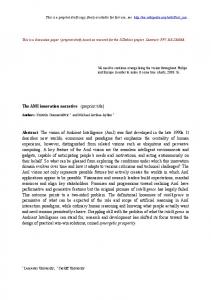
Then, in a second phase, the equipment was installed to the end-users’ homes for a minimum period of 15 days. The MAS module was connected to the HERA system for adapting the service to each user’s habits and needs. The users evaluated the system after both phases using a questionnaire capturing their satisfaction related to the following high level criteria: Performance (C1): It measures the capability of the system to produce valid and accurate results. Usability (C2): It measures the satisfaction of the user with regard to his experience in using the system and the ease of achieving his tasks. Flexibility (C3): It refers to the ease of troubleshooting and of moving from one service to another. Security and Trust (C4): the user trusts the system to securely handle his data and successfully manage his agenda.
84.00% 84.22%
C4
70.00%
C3
86.00% 83.07% 87.08%
C2
68.00%
C1
0.00%
85.83% 20.00%
40.00% Phase One
60.00% Phase Two
80.00%
100.00%
Figure 7. The performance and significance of the criteria for the end users in phases one and two of the trials Figure 7 shows the system’s performance for the end-user category for the first and second trial phases. The big difference in the performance criterion (C1) is mainly due to two factors, a) personalization and adaptation to user habits, as the software agents that assisted the users only became active in the second phase and b) system improvements according to the comments of the users. The Flexibility criterion (C3) was also better at home mainly because the end-users overcame their initial reservation on their ability to use HERA at home: the wider the extent of cognitive impairment, the lower the perceived ability to use the system without immediate assistance.
5. Conclusion This paper showed how a practitioner can apply the ASEME methodology for building an AmI system based on agent technology. It also presented a novel software architecture integrating a number of related technologies. ASEME has already been used for building a number of real world systems, e.g. for modeling the behavior of robotic teams, for an automated product pricing system, and for the development of a Hybrid Wind Turbine Monitoring System (for a complete list please consult http://www.amcl.tuc.gr/aseme/Publications.html). We suggest an AOSE methodology because there are more than one agents. The latter is more appropriate for agent-based development as the interaction part is not covered by conventional Software Engineering techniques. Moreover, the automated model transformation tools of ASEME help the engineer by facilitating the process from analysis and design to implementation and this is not the case for all the AOSE methodologies. Regarding the application domain, there are specific advantages of the HERA approach compared with previous works [9], [10]. The autonomy of the user is increased and the ambient assistance is automated [7]. The system validation results show that agent technology aids personal assistance in ambient intelligence environments. Our future work is related with integrating more sensors with a continuous flow of data for monitoring the user behavior aiming to detect his/her state and inform family members or call for help in the case of an abnormal situation (e.g. the user has fallen down and cannot get up). This calls for new types of agents for wrapping sensors and for event recognition at run-time. The original agent-based modeling of the system will allow for the seamless integration of new agents and functionalities.
References [1]
J. Nehmer, M. Becker, A. Karshmer, and R. Lamm, “Living assistance systems: an ambient intelligence approach,” in Proceedings of the 28th international conference on Software engineering, 2006, pp. 43–50.
[2]
M. Wooldridge, An Introduction to MultiAgent Systems. John Wiley & Sons, 2nd edition, 2009.
[3]
P. Bresciani, A. Perini, P. Giorgini, F. Giunchiglia, and J. Mylopoulos, “Tropos: An Agent-Oriented Software Development Methodology,” Auton. Agent. Multi. Agent. Syst., vol. 8, no. 3, pp. 203–236, May 2004.
[4]
F. Zambonelli, N. R. Jennings, and M. Wooldridge, “Developing multiagent systems: The Gaia methodology,” ACM Trans. Softw. Eng. Methodol., vol. 12, no. 3, pp. 317–370, Jul. 2003.
[5]
D. Harel and A. Naamad, “The STATEMATE Semantics of Statecharts,” ACM Trans. Softw. Eng. Methodol., vol. 5, no. 4, p. 293, 1996.
[6]
N. Spanoudakis and P. Moraitis, “Modular JADE Agents Design and Implementation Using ASEME,” in 2010 IEEE/WIC/ACM International Conference on Web Intelligence and Intelligent Agent Technology, 2010, pp. 221–228.
[7]
J. Marcais, N. Spanoudakis, and P. Moraitis, “Using Argumentation for Ambient Assisted Living,” in Artificial Intelligence Applications and Innovations, 2011, vol. 364.
[8]
R. Colombo and A. Guerra, “The Evaluation Method for Software Product,” in Proceedings of the 15th International Conference on Software & Systems Engineering & Applications, 2002.
[9]
J. Bravo, D. López-de-Ipiña, C. Fuentes, R. Hervás, R. Peña, M. Vergara, and G. Casero, “Enabling NFC Technology for Supporting Chronic Diseases: A Proposal for Alzheimer Caregivers,” in Ambient Intelligence, vol. 5355, E. Aarts, J. L. Crowley, B. Ruyter, H. Gerhäuser, A. Pflaum, J. Schmidt, and R. Wichert, Eds. Berlin, Heidelberg: Springer Berlin Heidelberg, 2008, pp. 109–125.
[10]
Ó. García, D. Tapia, A. Saavedra, R. Alonso, and I. García, “ALZ-MAS 2.0; A Distributed Approach for Alzheimer Health Care,” in 3rd Symposium of Ubiquitous Computing and Ambient Intelligence 2008, vol. 51, J. M. Corchado, D. I. Tapia, and J. Bravo, Eds. Berlin, Heidelberg: Springer Berlin Heidelberg, 2009, pp. 76–85.