SimSOTA: Engineering and Simulating Feedback Loops for Self-Adaptive Systems Dhaminda B.∗ Abeywickrama DiSMI, University of Modena & Reggio Emilia Italy
Nicklas Hoch
Franco Zambonelli
Corporate Research Group Volkswagen AG, Wolfsburg, Germany
DiSMI, University of Modena & Reggio Emilia Italy
[email protected]
dhaminda.abeywickrama@ unimore.it ABSTRACT
franco.zambonelli@ unimore.it
systems with the required level of reliability and availability. As a consequence, new software engineering methods and tools are required to make software systems autonomic [10, 14]. In the ASCENS EU-funded project, we investigate various models, schemes and mechanisms where both individual service components and service-component ensembles can become self-aware and self-adaptive. In this context, we have introduced the SOTA (State Of The Affairs) model [1] as a general goal-oriented framework for analyzing the self-awareness and self-adaptation requirements of adaptive systems. The SOTA model identifies an n-dimensional virtual-state space in which the execution of a system situates [1]. In the SOTA space, a system is self-aware if it can autonomously recognize its current position and direction of movement in the space, and self-adaptation means that the system is able to dynamically direct its trajectory. To achieve such capability, feedback loops are required inside the system. That is, they detect the current trajectory of the executing system, and then correct it so that specific regions of the space can be reached which correspond to specific application goals. SOTA defines many self-adaptive patterns in which feedback loops are organized [4]. However, there is a need to build solid engineering tools to support this design process. Engineering a decentralized system of autonomous service components and ensembles is very challenging for software architects. This is because there are a number of service components and managers that close multiple, interacting feedback loops. To better understand this complex setup, solid software engineering methods and tool support are highly desirable. Although several existing works (e.g. [12, 8, 16, 13, 18, 11, 15]) have addressed the need to make feedback loops explicit or first-class entities, very little attention has been given to providing actual tool support for the explicit modeling of these feedback loops, their simulation and validation. In this paper, we present a novel approach to architect and engineer self-adaptive systems based on feedback loops. Our work integrates both decentralized and centralized feedback loop techniques in order to exploit their benefits. We also present the first implementation of SimSOTA, an Eclipse plug-in that is being developed to support the modeling, simulating and validating of self-adaptive systems based on our feedback loop-based approach. The preliminary results of the approach for a single pattern were provided in [3].
Engineering a decentralized system of autonomous service components and ensembles having multiple and interacting feedback loops is very challenging. While several works have expressed feedback loops as first-class entities, very little attention has been given to providing actual tool support. In this paper, we propose a novel approach to architect and engineer self-adaptive systems based on feedback loops. We also present the first implementation of SimSOTA, an Eclipse plug-in being developed to support the modeling, simulating and validating of self-adaptive systems based on our feedback loop-based approach. We validate our approach using a case study in cooperative electric vehicles.
Categories and Subject Descriptors D.2.11 [Software Engineering]: Software Architectures— Patterns
General Terms Design
Keywords Autonomic systems, self-adaptive architectural patterns, selfawareness, simulation tools, software engineering
1. INTRODUCTION Software systems today are becoming increasingly complex and decentralized, and called to operate in open-ended and dynamic environments. It is therefore challenging and economically unbearable to develop, deploy and manage these ∗D. B. Abeywickrama is also affiliated with the Corporate Research Group, Volkswagen AG, Wolfsburg, Germany.
Permission to make digital or hard copies of all or part of this work for personal or classroom use is granted without fee provided that copies are not made or distributed for profit or commercial advantage and that copies bear this notice and the full citation on the first page. To copy otherwise, to republish, to post on servers or to redistribute to lists, requires prior specific permission and/or a fee. C 3 S 2 E -13 2013 July 10-12, Porto [Portugal] Copyright 2013 ACM 978-1-4503-1976-8/12/06 $15.00.
67
This paper presents the completed first implementation of the plug-in for two key patterns, integrating the decentralized and centralized feedback loop techniques. The goals of the SimSOTA plug-in are to support the modeling of the SOTA patterns’ structural and behavioral information using UML 2.2 diagrams; visual animation of the pattern behavior to expose run-time information; animating the composite structure of the patterns; run-time prompting during the pattern simulation; and model-level debugging with detailed control of execution of the patterns. We validate our approach using a case study in cooperative electric vehicles (e-mobility) [9]. The rest of the paper is organized as follows. Section 2 introduces the SOTA model and self-adaptation patterns. Section 3 presents our approach for engineering feedback loops. The case study is described in Section 4, and Section 5 discusses an example of the simulation to the case study. A discussion and evaluation of our approach is provided in Section 6, and Section 7 highlights key related work. Section 8 concludes the paper.
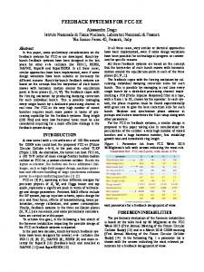
Figure 1: The trajectory of an entity in the SOTA space [1]. when a designer considers the actual architectural design of the system, it is important to identify which architectural schemes need to be chosen for the individual SCs and SCEs. SOTA helps to identify which scheme a feedback loop needs to be structured to enable self-adaptation. To this end, in [4] and [1] we defined a catalogue of architectural patterns for adaptive SCs and SCEs.
2. SOTA CONCEPTUAL MODEL The SOTA conceptual model conceives a self-adaptive software system as a dynamic system immersed in a virtual n-dimensional phase space, with each dimension associated with an internal or environmental parameter of interest for the execution of the system [1]. The execution of the system can then be modeled in terms of movements in such space. The dimensions of the SOTA space identify what the system should be aware of. A system is self-aware if it can autonomously recognize its current position and direction of movement in the SOTA space. A self-aware system using proper feedback loops can direct its own movements in the SOTA space. Self-adaptation is associated with the capability of the system to rejoin proper trajectories when the system tries to deviate from them, so goals are eventually achieved. The SOTA model assumes that the systems under study comprise service components (SC), which are intended as goal-oriented computational/software nodes to serve in open and non-deterministic environments. The SCs are possibly grouped into service-component ensembles (SCE), a group of SCs that share a set of common goals. In SOTA, a goal by definition is the achievement of a given state of the affairs. Therefore, in general terms, a goal Gi for the entity e (an individual SC or SCE) can be represented as a specific point, or more generally an area in the virtual space S. More specifically, a goal Gi of an entity e may not necessarily be active all the time. In such instance, it is useful to characterize a goal in terms of a precondition Gpre i and a postcondition Gpost to express when the goal has to i activate and what its achievement implies (see Fig. 1). As goals represent the eventual state of the affairs that a system or component has to achieve, they can be considered functional requirements. However, in many cases, a system should try to reach its goals by adhering to specific constraints on how such goals can be reached. We call these types of constraints on the trajectory or execution path that a system should try to respect utilities U (see Fig. 1), and these correspond to non-functional requirements. The SOTA modeling approach is key to understanding and modeling self-awareness and adaptation, and for checking the correctness of the specification [1, 2]. However,
3.
ENGINEERING FEEDBACK LOOPS FOR SELF-ADAPTIVE SYSTEMS
This section discusses the notion of feedback loops explored in SOTA to express self-awareness and self-adaptation, and the conceptual view of our approach for two key SOTA patterns.
3.1
Notion of Feedback Loops in SOTA
A feedback loop provides a generic architectural mechanism for adaptation where it provides means for inspecting and analyzing the system at the SC or SCE level and for reacting accordingly, so goals can eventually be achieved [3]. The notion of feedback loops explored in SOTA [3] extends the well-established IBM’s MAPE-K adaptation model [10] (i.e. monitor, analyze, plan, execute over a knowledge base) with multiple, interacting loops. Advanced software systems that are often highly decentralized require the modeling of multiple interacting control loops. Multiple feedback loops can coordinate and support adaptation using two basic mechanisms: inter-loop and intra-loop coordination [16]. Intra-loop coordination is provided by multiple sub-loops within a single feedback loop, which allows the various phases of MAPE-K in a loop to coordinate with one another. In contrast, inter-loop coordination supports the coordination of adaptation across multiple control loops. These inter-loops can interact using three basic mechanisms: hierarchy, stigmergy and direct interaction [13]. In stigmergy, loops act on a shared subsystem where a manager makes changes to the shared subsystem that can be sensed by another manager. In hierarchy, a loop directly controls another loop, which typically occurs inside a single feedback structure where an outer loop controls an inner loop. In direct interaction, managers act as peers communicating with each other, and this typically occurs when they are controlling a common resource. Also,
68
two types of feedback loops can be identified depending on the nature of feedback, that is, positive and negative [5]. Both decentralized and centralized feedback loop approaches have been suggested to facilitate autonomic behavior in adaptive systems [7]. We integrate these approaches in order to exploit the benefits of both. Although centralized approaches allow global behavior control, they contain a single point of failure and suffer from scalability issues [19]. Conversely, decentralized approaches do not require any a priori knowledge, nor do they contain a single point of failure. SOTA identifies and classifies patterns based on the above described dimensions, and defines a taxonomy that is helpful for the engineering of multiple and possibly interacting feedback loops, in particular for choosing among a variety of feedback loop compositions.
Managed Element SC1
Sensors
Effectors
SOTA Goals
UML Action Language, Guard conditions
Inter-loop coordination: stigmergy/hierarchy/ direct interaction
requires >
AM1
requires >
Goal Pre & Postconditions
requires >
SOTA Dimension S1
change plan > request for change >
Feedback Loop #1 symptom >
Analyze
Execute
Plan
Intra-loop coordination
Knowledge
Monitor AM2 SOTA Dimension S2
change plan > request for change >
Feedback Loop #2
3.2 Conceptual View of the Approach for Key SOTA Patterns
symptom >
To clarify the ideas behind our approach, we present the conceptual view of our approach for two key SOTA architectural patterns at the SC and SCE levels: the Decentralized SC pattern and the Centralized SCE pattern. The Decentralized SC pattern is characterized by the presence of an explicit, external feedback loop to direct the behavior of the managed element (see Fig. 2). The managed element has sensors, effectors and a representation of SOTA goals. The SOTA utilities are enforced in the managers. An autonomic manager (AM) handles the adaptation of the managed element. Several AMs can be associated with the managed element, each closing a feedback loop devoted to controlling a specific adaptation aspect of the system. Adding different levels of AMs increases the autonomicity, and these extra AMs work in parallel to manage the adaptation of the managed element. For instance, let us consider that we have two feedback loops with an AM in each loop to handle adaptation in two SOTA dimensions (see Fig. 2). These loops can interact with each other using hierarchy, stigmergy or direct interaction, and here we can identify an inter-loop coordination where MAPE-K computations of the loops coordinate with each other. An intra-loop can be identified between the Analyze and Knowledge components of an AM to allow the coordination of adaptation between these two phases. Depending on the nature of the feedback, the feedback loops can be either positive or negative. The Centralized SCE pattern is characterized by a global feedback loop, which manages a higher-level adaptation of behavior of multiple autonomic components (see feedback loop for SC1 and SC2 in Fig. 3). The adaptation in the Centralized SCE pattern is handled by a super AM, and like an AM it has the MAPE-K adaptation model (e.g. Super AM1). This is while the single SCs (SC1 and SC2, Fig. 3) are able to self-adapt their individual behavior using their own external feedback loops (AM1 and AM2 for SC1, and AM 3 for SC2). Alternatively, the Centralized SCE pattern can contain a super AM which is a high-level manager (closing an outer loop) that interacts and manages another AM or several AMs (closing inner loops), thus dealing with multiple awareness dimensions (Super AM2 managing AM1 and AM2). As in the Decentralized SC pattern, the feedback loops in this pattern can interact using hierarchy, stigmergy or direct interaction, and the loops can be either positive or negative type.
Analyze
Execute
Plan Legend
Intra-loop coordination
feedback loop for AM composition
Knowledge
Monitor
Figure 2: Decentralized SC pattern. Managed Element SC1
Managed Element SC2
(black box component)
(black box component)
requires >
AM1
AM3
(black box component)
(black box component)
requires >
AM2
(black box component)
Super AM2
Global Feedback Loop
(black box component)
Super AM1 change plan > request for change > symptom >
Monitor
Analyze
Execute
Plan Legend
Intra-loop coordination
Knowledge
feedback loop for AM feedback loop for Super AM composition
Figure 3: Centralized SCE pattern.
4.
E-MOBILITY CASE STUDY PROBLEM AND AUTOMATION WITH SOTA
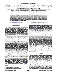
This section addresses the e-mobility case study problem using the SOTA model’s self-awareness and self-adaptation mechanisms. The e-mobility case study is used to explore and validate our simulation. The scenario concerns individual planning and mobility for a single user and a privately owned vehicle. Let us consider a situation where a user intends to travel to an appointment at a particular destination [9]. Fig. 4 (top portion) illustrates the temporal sequence of the mobility events related to a single appointment. First, the user drives the electric vehicle (e-vehicle) to the car park, then parks the car and walks to the meeting location. During the walking and meeting times, the e-vehicle can be recharged. Here, the main SCs are the user or driver, the e-vehicle, and the parking lots and charging stations (infrastructure). The main SCEs are (1) the temporal orchestration of the user, the e-vehicle, a parking lot and a charging station assigned at trip start (User-E-Vehicle-Assigned-Infrastructure
69
Temporal sequence of mobility events User SC E-Vehicle SC
Appointment
Walk
Drive
Park
User-E-Vehicle-Assigned-Infrastructure SCE 1
1 1 1
User SC SOTA Goals
Walk Drive
Charge
Sensors
Parking Lots SCE n Parking Lot SC n n SOTA Sensors
E-Vehicle SC SOTA Goals
t
Charge
Goals
Sensors Effectors
n
Effectors
Effectors
AM -- Availability
MAPE-K
AM -- State of Charge Super AM -- Availability of
MAPE-K
1
1 Parking Lots
MAPE-K
1 AM -- Climate Comfort MAPE-K
Charging Stations SCE
1 AM -- Driving Styles
m Charging St.SC m Sensors m SOTA Goals
MAPE-K
1
Super AM -- Routing
1
Super AM -- User Prefs.
Effectors
MAPE-K
MAPE-K
m AM -- Availability MAPE-K Assigned Charging St.SC
1 Assigned Parking Lot SC 1
SOTA Goals
Sensors
1
Effectors
AM -- Availability
1
MAPE-K
1
SOTA Goals
Super AM -- Availability of
1 Charging Stations
Sensors
MAPE-K
Effectors Super AM -- Availability of
AM -- Availability
1
1 Parking Lots & Charging St.
MAPE-K
MAPE-K Legend
Super AM -- Availability of Assigned Infrastructure
MAPE-K
n, m, 1
Feedback loop for AM Feedback loop for Super AM SCE (Ensemble) Multiplicities of the associated SCs
Figure 4: SOTA patterns applied to the e-mobility scenario. SCE ); (2) a collection of available parking lots (Parking Lots SCE ); and (3) a collection of available charging stations (Charging Stations SCE ) (see Fig. 4). The e-mobility case study problem is well suited to be solved using appropriate self-awareness and self-adaptation mechanisms (e.g. the SOTA model) for the following reasons:
the plan; (2) user SC: the shifting of an appointment; and (3) parking lot and charging station SCs: the evehicle does not arrive at the booked time or it leaves earlier or later; charging is not initiated at the foreseen time and draws unforeseen amounts of power. In the SOTA model, the SCs are conceptually modeled as entities (e) moving and executing in the space (S), and these entities can have goals (G) and utilities (U ) that describe how such goals can be achieved at an individual or a global level. Each SC and SCE of the mobility scenario can be described using the SOTA goals and utilities, the awareness being monitored for each managed element, and the self-adaptive behavior using SOTA feedback loops as a response to any contingencies that may occur. For example, let us consider the e-vehicle SC, which is the central SC within the mobility scenario. It interfaces with both the user and the infrastructure SCs during driving, and with the infrastructure SCs only during parking or walking. The goal (Gi ) of the e-vehicle is to reach the destination with the planned energy and at the planned time. A utility (Ui ) can be the constraint that the battery charge should not reach ‘low’ until the e-vehicle reaches its destination. The monitored awareness dimensions (S) are, among others, the state of the battery charge, temperature (for climate comfort requirements of the user), acceleration and velocity (for driving style requirements), and the vehicle’s current location. Examples of self-adaptive actions to handle contingency situations are changing the booking, route or driving style. Based on this modelization, we can derive a characterization of feedback loops. As shown in Fig. 4, in order to handle the adaptation of
• The case study problem involves a significant number of SCs. Therefore, relying only on centralized solutions becomes unfeasible and providing for decentralized solutions to handle localized decision making is important. • This problem deals with several awareness dimensions that need to be handled by the complex SCs, e.g. evehicle SC: time, energy, location; user SC: user preferences (climate comfort, driving style), time, cost; parking lots and charging stations SCs: availability. • Each SC has access only to partial information or partial view of the environment (e.g. during the trip, the e-vehicle is not aware of the availability of its assigned parking lot). Therefore, the individual SCs need strategies to adapt at run-time as more information becomes available to them. • Each SC and SCE is involved in significant levels of uncertainty or contingency situations (system or environmental changes) requiring self-adaptive actions. These can be (1) e-vehicle SC: the unavailability of a parking lot; the planned event deadline is missed (the e-vehicle could not reach the destination at the time required or with the energy planned); the user overrides
70
a managed element, we can provide separate AMs for each SOTA awareness dimension. The e-vehicle SC has three AMs defined to handle the adaptation of the battery state of charge (SoC), climate comfort and driving style requirements of the user. Any self-adaptive behavior on routing needs to be handled at the SCE level, as these actions are applicable to both the user and the e-vehicle SCs. Thus, a super AM has been defined to handle the adaptation of routing. Also, a super AM has been specified to handle the adaptation of user preferences, which manages multiple AMs and awareness dimensions (i.e. AMs on climate comfort and driving style). The parking lot SCs and charging station SCs need to be aware of their availability. To handle possible contingency situations, two separate AMs can be defined to manage the availability of the two assigned infrastructure SCs, and a super AM can be provided to handle the adaptation of both SCs. Meanwhile, the Parking Lots SCE and the Charging Stations SCE (see Fig. 4) can contain AMs to manage the availability at the individual SC level, and two super AMs to handle the adaptation of the collections of parking lot and charging station SCs, respectively. As seen here, it is clear that there are a number of SCs, SCEs, AMs and super AMs closing multiple, interacting feedback loops. These feedback loops, which SOTA uses as mechanisms to express self-awareness and self-adaptation, can be organized using several architectural patterns. Therefore, the aim of our work is to provide engineering support to the software engineer in order to easily grasp this complex setup.
The developers are enabled to effectively build models of the complex systems of feedback loops. As of now, the SimSOTA models have been implemented with regard to a limited number of key SOTA self-adaptive patterns, and for the specific case study of e-mobility. However, the idea of SimSOTA is to make templates and models available for all the key patterns, and to facilitate general-purpose and application-independent instantiation of simulations for complex systems based on feedback loops.
5.1
Modeling and Simulating of SOTA Feedback Loops
We have used UML 2.2 activity models as the primary notation to model the behavior of feedback loops. A feedback loop is essentially the interplay between flow (control or data) and actions on the flows. In a feedback loop, the actions are not necessarily performed sequentially. An iterative process allows the revision of certain decisions if required, and therefore activity diagrams are effective to design the feedback loops. The SimSOTA plug-in also facilitates the simulation of feedback loops in other UML 2.2 diagrams, such as composite structure and sequence diagram models. We now describe the models realized in SimSOTA to simulate a number of feedback loop structures in the User-EVehicle-Assigned-Infrastructure SCE of the e-mobility scenario (Fig. 4). Note that due to space considerations, the activity model provided in Fig. 5 is a subset of the UserE-Vehicle-Assigned-Infrastructure SCE, while the composite structure model provided in Fig. 6 corresponds to the entire SCE.
5. SIMSOTA ECLIPSE PLUG-IN In this section, we present the key rationale underlying the SimSOTA plug-in and describe how we have applied it to the e-mobility case study. This is to clarify how the plugin works and its usage. The plug-in is developed using the IBM Rational Software Architect Simulation Toolkit 8.0.4. The key objectives of the SimSOTA plug-in are:
5.1.1
SCs and Managers
There are several managed elements or SCs: the e-vehicle (SC_EVehicle; Fig. 5, top-center), the user (SC_User; Fig. 5, top) and the assigned parking lot (SC_ParkingLotAssigned; Fig. 5, middle-right). The AMs - AM_EV_ClimateComfort and AM_EV_SoC - close separate, decentralized feedback loops to handle the adaptation of climate comfort and battery charge level in the e-vehicle, respectively. Similarly, AM_PL_Availability provides a decentralized feedback loop to handle the adaptation of availability for the assigned parking lot. Also, there are two super AMs that close separate, centralized feedback loops. As stated in Section 3.2, a super AM can manage the adaptation of multiple SCs, or it can be a high-level manager managing one or several AMs. Here, SAM_EVUser_Routing handles the adaptation of routing for the e-vehicle and the user SCs, and SAM_User_UserPreferences handles user preferences by managing AMs on climate comfort and driving style.
• Modeling: The modeling of the key SOTA patterns using UML 2.2 where the patterns’ structural and behavioral information are modeled using activity, sequence and composite structure diagrams. • Simulation: The simulation of the key SOTA patterns to better understand their complex and dynamic model behavior. We aim to visually animate the SOTA patterns’ behavior during execution to expose the runtime view of the simulated model, such as next element to execute, executed element, active states and tokens. We further aim to animate composite structures of the SOTA patterns, for example, interaction messages and execution history information of the simulation. Additionally, run-time prompting allows the engineer to interact with the simulation during its model execution.
5.1.2
SOTA Goals and Utilities
Each managed element (e.g. SC_EVehicle) has an activitybased UML model to represent SOTA goals. We can consider a goal (Gi ) called reach destination for the SC_EVehicle, and this can be characterized in terms of a precondition and a postcondition (Fig. 5, top-center). The preconditions and postconditions of the SOTA goals are modeled using UML Action Language and guard conditions. Here, the precondition (Gpre i ) checks whether the assigned parking lot is available, and the postcondition (Gpost ) is the actual reaching of i the destination within the state of battery charge and time.
• Validation: The validation of the feedback loop models and their interplay to detect errors early and to check whether the specified behavior works as intended. This is done by using model-level debugging with detailed control of execution, such as breakpoints, stepping, suspending, resuming and terminating. The general goal of SimSOTA is to facilitate the engineering of complex self-adaptive systems based on feedback loops.
71
Figure 5: Patterns simulated as an activity model for an e-mobility scenario.
72
The utilities (U ) for SC_EVehicle are constraints on the state of the battery charge, climate comfort, driving style (acceleration and velocity), and routing requirements until the e-vehicle reaches its destination, which is its goal. They have been modeled in the managers, and to this end, the Analyze phase of a MAPE-K loop can contain decision nodes with guard conditions to check and enforce the required constraints. For instance, see guard conditions defined in AM_EV_SoC (Fig. 5, top-right) to check whether the level of the battery charge is low or not. The SimSOTA plug-in integrates both decentralized and centralized feedback control loop techniques using the SOTA patterns - decentralized SC and centralized SCE - to handle the adaptation of the managed elements. The loops interact with each other using stigmergy, hierarchy or direct interaction (inter-loop coordination). In this example, as the feedback loops deal with counteracting perturbation situations, they are of the negative feedback type.
acts according to the interpreted symptoms. For instance, if it interprets that the booking for the assigned parking lot has been canceled or the parking lot is unavailable now, it triggers and devises a plan to execute change. Then the Execute phase of the loop searches for other available parking lots close by, and notifies the SAM_EVUser_Routing to rebook and replan the route for the e-vehicle. Here, we can identify a direct interaction between the two managers, AM_PL_Availability and SAM_EVUser_Routing (see also Fig. 6, bottom-left). In response, the SAM_EVUser_Routing updates the parking lot bookings in the e-vehicle, and replans the route and notifies it to the e-vehicle. An example of the hierarchy interaction can be identified between the managers - SAM_User_UserPreferences, AM_EV_ClimateComfort and AM_EV_DrivingStyle. Here, the managers form a feedback structure where the outer loop provided by the super AM directly acts and controls the inner loops managing climate comfort and driving style. This is because the user preferences are derived using values sensed for climate comfort and driving style (see Fig. 6, middle-right).
5.1.3 Decentralized Feedback Loops and Interactions The Sensor components in SC_EVehicle form concurrent activities for measuring the battery charge, temperature (for climate comfort), location (for routing), acceleration and velocity (for driving style) inside the e-vehicle, respectively (see Fig. 5, top-center). These concurrent activities close several decentralized feedback loops in the AMs which interact using stigmergy and act on its shared subsystem (see also Fig. 6, top). For example, the Monitor component in AM_EV_SoC (Fig. 5, top-right) collects the battery charge data from the Sensors and filters the accumulated data. The events signals of the state of battery charge are then stored in the Knowledge component. Knowledge also stores an abstract representation of the SOTA goals and utilities. The Analyze component gathers the temperature signals and the adaptation goals and interprets battery charge data against the patterns. Here we can identify an intra-loop to coordinate the adaptation between the Analyze and Knowledge components. A decision node exists to check whether the battery charge level is within the limit or not, and then the battery level symptoms result is stored in Knowledge. The Plan component obtains battery level symptoms and interprets them. If the battery charge level is low then it triggers and devises a plan to execute battery level change. To achieve this, the Execute component notifies the SoC effector in the SC_EVehicle, which accordingly notifies the user about the battery charge level inside the e-vehicle.
5.2
Visual Animation and Validation of SOTA Feedback Loops
The SimSOTA plug-in supports the visual animation of the SOTA patterns’ behavior during execution to expose run-time information, such as the next element to execute (highlights the next element to be executed in the patterns simulation), the executed element (the current element being executed), active states, and tokens (the elements in the model that are ready to execute) (see Fig. 5, bottom-center). The run-time prompting feature allows the engineer to interact with the simulation when an informal construct of the activity model is encountered. For example, a dialog box appears in AM_EV_SoC to check whether the battery level is low, and the option the engineer selects decides which outgoing activity edge of the model gets executed next. The simulation facilitates the animation of feedback loops in other UML 2.2 diagrams as well, such as composite structure and sequence diagram models. The composite structure model (Fig. 6) simulates the behavior of feedback loops between SCs and managers of an SCE, collaborating over communication links. This is simulated according to the interaction messages that occur between components in a corresponding activity diagram model or sequence diagram model for the same system. The execution history information of the feedback loop in the SCE is animated by means of colored arrows, which show how interaction messages occur between the components. The number in a flow indicates the order in which the flow or interaction occurred at run-time. As for validation, the simulation can be used to detect modeling errors early and to check whether the specified feedback loop behavior works as intended. It allows us to find and fix any problems that may occur in the complex interactions between the SCs and managers. To achieve this, the plug-in facilitates model-level debugging and the detailed control of execution of patterns with breakpoints and other commands, such as stepping (step through the execution of behavior element at a time), suspending (break the execution of the simulation), resuming (run the simulation until it completes its execution or meets a breakpoint), terminating (stop the current simulation session) and restarting. For instance, breakpoints can be created in the
5.1.4 Centralized Feedback Loops and Interactions The two super AMs defined for managing the adaptation of routing (SAM_EVUser_Routing; Fig. 5, middle-center) and user preferences (SAM_User_UserPreferences; Fig. 5, middle-left) close separate, centralized (global) feedback loops. The SAM_EVUser_Routing deals with contingency situations if the e-vehicle misses its deadline. It has activities for monitoring and analyzing location data of the e-vehicle against goals, and if the loop’s Plan phase interprets the e-vehicle missing the deadline, it devises a plan to execute change. In response, the Execute component replans the route and notifies the new route to the e-vehicle. The SAM_EVUser_Routing also reacts to interactions with other AMs. The Plan component in AM_PL_Availability (Fig. 5, bottom-right) interprets availability symptoms and
73
Figure 6: Patterns simulated as a composite structure model.
Supporting Application-Independent Simulations.
complex super AM, SAM_EVUser_Routing, and we can execute the simulation until it meets the breakpoints (Fig. 5, bottom-center). Then, we can move through the activities step by step, examining and validating the complex interactions that associate with this super AM, such as the direct interactions with AM_PL_Availability.
As mentioned earlier, at present the SimSOTA models have been created for a limited number of key SOTA selfadaptive patterns applied to e-mobility. However, the general idea is to build templates and models for all the key SOTA patterns of the catalogue, and to facilitate generalpurpose and application-independent instantiation of simulations for complex systems based on feedback loops. This could be performed by introducing an abstract UML model or template (custom UML profile applied) for each key SOTA pattern, which could then be deployed with the SimSOTA plug-in to support the modeling of the patterns. A custom UML profile introduces a set of stereotypes that extends the existing meta-model of UML to a specific area of application. Here, a custom UML profile can be created to specify the required semantics of the SOTA decentralized SC pattern and the centralized SCE pattern discussed in this paper. This profile can contain a set of stereotypes applying the different elements of the two patterns, such as an AM, a super AM, the MAPE-K phases, an SC or SCE, the SOTA goals, the sensors and effectors. It can also contain stereotypes for the different dependency relationships of the patterns, such as stigmergy, hierarchy and direct interaction. Applying this profile, two abstract UML models or templates can be created. These templates can contain (1) architecturally significant, reusable UML model elements that are unique to the pattern; and (2) any textual advice to the engineer on applying the profile and deriving domainspecific models in a consistent manner. Thus, the SimSOTA plug-in can support the modeling of the key SOTA
5.3 Deployment as an Eclipse Plug-in We have deployed our first implementation of the simulation, which is composed of activity, sequence and composite structure models for a limited number of key SOTA patterns and for the e-mobility case study, as an Eclipse plug-in [6]. The goal is eventually to allow our tool to be leveraged by other interested researchers. First, using the IBM Rational development environment, the simulation was converted to a plug-in project, adding the plug-in development environment capability. Second, the plug-in was packaged in such a way that an engineer can install it in their environment. The plug-in can be exported to a directory, an archive file, or in a runnable format installed into the currently running Eclipse host. The installed Eclipse plug-in was tested using the self-hosting mechanism, which is a powerful debugging and testing tool. To this end, the Eclipse application launcher was used to create a second running instance of Eclipse that runs the SimSOTA simulation.
6. DISCUSSION AND LESSONS LEARNT In this section, we discuss some characteristics of our approach and the SimSOTA plug-in, and present the main lessons learnt from this research experience.
74
self-adaptation patterns for the engineer in an applicationindependent manner.
that extends IBM’s MAPE-K model with support for two types of adaptation coordination: intra-loop and inter-loop. While their work is comprehensive in coordinating and integrating multiple control loops, the MAPE-K loops used do not support an integration of decentralized and centralized adaptation coordination as provided in our work. To manage the complexity of internet applications, the authors in [13] propose a set of weakly interacting (i.e. stigmergy, hierarchy and direct interaction) feedback structures where each structure consists of a set of feedback loops to maintain one system property. As in our work, in [18] a feedback loop has been represented as a flow of information and actions, and UML activity diagrams have been used as notation. However, unlike our approach, both [13] and [18] have not provided detailed individual steps of the adaptation process nor have they provided tool support for modeling, simulation and validation of the feedback loop models. Vogel and Giese [15] establish a domain-specific modeling language for run-time models called megamodels and an interpreter to execute them. Using the modeling language, single and multiple feedback loops and their interplay can be explicitly specified in the megamodels. Like our approach, their work has considered detailed individual adaptation steps like monitoring, analysis, planning and execution. Also, their modeling language is similar to the UML activities used in our work with respect to modeling flows of actions or operations. However, the authors have not considered any validation of the simulated feedback loop models in [15]. Compared to previous approaches to the engineering of self-adaptive systems using feedback loops, to the best of our knowledge, there has been no implementation or tool support to address the needs of software architects. The present work aims to contribute towards this end.
SOTA Self-Adaptation Patterns and Model-Driven Development. The application of model-driven development offers new opportunities in the development of self-adaptive software systems [5]. An important and added benefit of creating UML profiles-applied templates for the patterns is that it allows one to apply model-driven development techniques such as model transformations. That is, such profiles and templates can not only be used to automate the modeling of patterns for the engineer in an application-independent manner as discussed earlier, but also to automate the generation of platform-specific implementation code. This could be performed by creating a set of transformations (model-to-model and model-to-text), which recognize and transform the pattern elements with stereotypes modeled at the platformindependent level. Accordingly, we can support the engineering and development of patterns in different phases of the software life-cycle.
Additional Considerations. Feedback loops are mechanisms in the architecture that SOTA uses for expressing self-awareness and self-adaptation. Our work applies an explicit modeling approach, that is, instead of modeling adaptation behavior that realizes a feedback loop as a black box component, we model each step in detail. For instance, the activity models of feedback loops have a series of activities created for monitoring, analyzing, planning and executing over a knowledge base (Fig. 5). Also, as the adaptation is specified at a higher level of abstraction (i.e. the software architectural level using UML 2.2), it ensures an easy integration into model-based development approaches. Furthermore, our approach removes the need to build actual implementation models of sensors and effectors to monitor and control adaptation, which can be costly. This is because our executing simulation models of the feedback loops serve as abstract representations of their actual implementations. By contrast, code-based solutions require significant effort to build the necessary sensors and effectors [19].
8.
CONCLUSIONS AND FUTURE WORK
Engineering a decentralized system of autonomous SCs and SCEs is very challenging for software architects. To better understand this complex setup, solid software engineering methods and tool support are highly desirable. The main contributions of this paper are: (1) a novel approach to architect and engineer multiple, interacting feedback loops, which SOTA uses as mechanisms to express self-awareness and self-adaptation. Our model uses an integration of decentralized and centralized feedback loop approaches; and (2) the first implementation of SimSOTA, an Eclipse plug-in being developed for the explicit modeling, simulating and validating of self-adaptive systems based on our feedback loopbased approach. Furthermore, this paper has addressed the electric vehicles case study problem using the SOTA model’s self-awareness and self-adaptation mechanisms. The future work planned is twofold. First, we will be exploiting the results of our simulation experiences to produce effective software engineering guidelines and possibly some requirements for the associated tools. This is to aid the design and development of self-adaptive systems. Second, we will be extending the first implementation of SimSOTA to support application-independent simulations for complex systems. This in turn will help us extend the simulation models at the architectural level to the Java-based implementation level. To this end, we will apply transformations to automate the translation of key SOTA self-adaptation patterns modeled in UML 2.2 into textual Java. Then, the
7. RELATED WORK In 2001, IBM introduced the notion of autonomic computing and provided a reference model for autonomic control loops known as MAPE-K loops [10]. Later, a formal reference model was introduced in [17] to describe self-adaptive systems, based on the MAPE-K model and other key adaptation models. Several authors (e.g. [12, 8, 16, 13, 18, 11, 15]) have emphasized the need to make feedback loops first-class entities in self-adaptive systems. Muller, Pezze and Shaw [12] discuss an approach to increase the visibility of control loops to support their continuous evolution. They highlight the need for multiple control loops in an adaptive ultra large-scale system, and stress the need for refining the loops into reference models and design patterns. Although these ideas have been discussed at the conceptual level, no implementation or validation of the work using techniques such as simulations has been reported [12]. Vromant et al. [16] describe an implementation framework
75
SOTA patterns in Java will be integrated with the Javabased framework of the e-mobility system for validation. The e-mobility framework will utilize realistic data by a traffic simulator, and later through actual Web services.
[14]
9. ACKNOWLEDGMENTS [15]
This work is supported by the ASCENS project (EU FP7FET, Contract No. 257414).
10. REFERENCES
[16]
[1] D. B. Abeywickrama, N. Bicocchi, and F. Zambonelli. SOTA: Towards a general model for self-adaptive systems. In Proc. of the IEEE 21st International WETICE Conference, pages 48–53. IEEE, June 2012. [2] D. B. Abeywickrama and F. Zambonelli. Model checking goal-oriented requirements for self-adaptive systems. In Proc. of the 19th Annual ECBS’12 Conference, pages 33–42. IEEE, Apr. 2012. [3] D. B. Abeywickrama, F. Zambonelli, and N. Hoch. Towards simulating architectural patterns for self-aware and self-adaptive systems. In Proc. of the 2nd Awareness Workshop co-located with the SASO’12 Conference, pages 133–138. IEEE, Sept. 2012. [4] G. Cabri, M. Puviani, and F. Zambonelli. Towards a taxonomy of adaptive agent-based collaboration patterns for autonomic service ensembles. In Proc. of the International Conference on Collaboration Technologies and Systems, pages 508–515. IEEE, 2011. [5] B. Cheng, R. de Lemos, H. Giese, P. Inverardi, J. Magee, et al. Software engineering for self-adaptive systems: A research roadmap. In Software Engineering for Self-Adaptive Systems, volume 5525 of LNCS, pages 1–26. Springer-Verlag, 2009. [6] E. Clayberg and D. Rubel. Eclipse Plug-ins. Addison-Wesley Professional, 3 edition, 2008. [7] T. Haupt. Towards mediation-based self-healing of data-driven business processes. In Proc. of the 7th International SEAMS Symposium, pages 139–144. IEEE/ACM, june 2012. [8] R. Hebig, H. Giese, and B. Becker. Making control loops explicit when architecting self-adaptive systems. In Proc. of the 2nd International Workshop on Self-Organizing Architectures, pages 21–28. ACM, 2010. [9] N. Hoch, K. Zemmer, B. Werther, and R. Y. Siegwart. Electric vehicle travel optimization—customer satisfaction despite resource constraints. In Proc. of the 4th Intelligent Vehicles Symposium, pages 172–177. IEEE, 2012. [10] J. O. Kephart and D. M. Chess. The vision of autonomic computing. IEEE Computer, 36(1):41–50, 2003. [11] M. Luckey, B. Nagel, C. Gerth, and G. Engels. Adapt cases: extending use cases for adaptive systems. In Proc. of the 6th International SEAMS Symposium, pages 30–39. ACM, 2011. [12] H. M¨ uller, M. Pezz`e, and M. Shaw. Visibility of control in adaptive systems. In Proc. of the 2nd International Workshop on Ultra-Large-Scale Software-Intensive Systems, pages 23–26. ACM, may 2008. [13] P. V. Roy, S. Haridi, and A. Reinefeld. Designing robust and adaptive distributed systems with weakly
[17]
[18]
[19]
76
interacting feedback structures. Technical report, ICTEAM Institute, Universit´e catholique de Louvain, 2011. E. Vassev and M. Hinchey. Awareness in software-intensive systems. Computer, 45(12):84–87, 2012. T. Vogel and H. Giese. A language for feedback loops in self-adaptive systems: Executable runtime megamodels. In Proc. of the 7th International SEAMS Symposium, pages 129–138. IEEE/ACM, june 2012. P. Vromant, D. Weyns, S. Malek, and J. Andersson. On interacting control loops in self-adaptive systems. In Proc. of the 6th SEAMS Symposium, pages 202–207, 2011. D. Weyns, S. Malek, and J. Andersson. FORMS: a formal reference model for self-adaptation. In Proc. of the 7th International Conference on Autonomic Computing, pages 205–214. ACM, 2010. T. D. Wolf and T. Holvoet. Using UML 2 activity diagrams to design information flows and feedback-loops in self-organising emergent systems. In T. D. Wolf, F. Saffre, and R. Anthony, editors, Proc. of the 2nd International Workshop on Engineering Emergence in Decentralised Autonomic Systems, pages 52–61, 2007. J. Wuttke, Y. Brun, A. Gorla, and J. Ramaswamy. Traffic routing for evaluating self-adaptation. In Proc. of the 7th International SEAMS Symposium, pages 27–32. IEEE/ACM, june 2012.