INTERNATIONAL JOURNAL OF PRECISION ENGINEERING AND MANUFACTURING Vol. 13, No. 10, pp. 1753-1758
OCTOBER 2012 / 1753
DOI: 10.1007/s12541-012-0230-0
Enhanced CNC Machines Capabilities by Adding Circular Patterns Cycle Adel Taha Mohamed Abbas1,# 1 Department of Mechanical Engineering, Engineering College, King Saud University, Riyadh 11421, P.O. Box 800, Kingdom of Saudi Arabia # Corresponding Author / Email:
[email protected], TEL: +966-1-4679799, FAX: +966-1-4676652 KEYWORDS: CNC machining, NC programming algorithms, Canned cycles, User-defined cycles
Holes in multiple circular patterns exist in several recent industrial parts such as antennas, heat exchanger support plates, condensers, boilerplates, trammel screens and separators. There is a lot of difficulty in preparing CNC programs using conventional programming or canned cycle programming. This study illustrates an effort to establish a practical common algorithm allowing the drilling of holes arranged in multiple circular patterns. The programmed algorithm can easily be adapted to any modern CNC unit to create a user cycle or subroutine. To test the capabilities of this algorithm, two case studies were developed. The first used the Numeripth800-B CNC unit equipped with a horizontal Orion-500 machining center, and the second case study was developed using the Sinumeric 840-D equipped with a vertical Emco machining center. A number of samples were produced successfully. The new algorithm shows high efficiency in the part program establishment and offers the advantage of decreasing the encoding errors. Manuscript received: December 10, 2011 / Accepted: June 3, 2012
1. Introduction Numerical control (NC) refers to the automation of machine tools that are operated by abstractly-programmed commands that are encoded in storage medium; this is in contrast to hand tools that are manually controlled via hand wheels, levers or are mechanically automated via cams alone. The first numerically controlled machines were built in the 1940s and 1950s and were based on existing tools that were modified with motors that moved the controls to follow points fed into the system on a punched tape. These early servomechanisms were rapidly augmented with analog and digital computers, which created the modern computer numerical control (CNC) machine tools that have revolutionized the manufacturing process. In modern CNC systems, end-to-end component design is highly automated using computer-aided design (CAD) and computer-aided manufacturing (CAM) programs. These programs produce a computer file that is interpreted to extract the commands needed to operate a particular machine via a postprocessor, and the programs are then loaded into the CNC machines for production. Because any particular component might require the use of a number of different tools (drills, saws, etc.), modern machines often combine multiple tools into a single “cell”. In other cases, a number of different machines are used with an external controller and human or robotic operators that move the © KSPE and Springer 2012
component from machine to machine. In either case, the complex series of steps needed to produce any part is highly automated and produces a part that closely matches the original CAD design.1 The invention relates generally to computer numerical control for industrial machines and, more particularly, to a method of defining and executing customized canned cycles in a computer numerical controlled machine. A computer numerical control responds to part program commands to perform the desired machining operation according to the information contained in the part program. The part program contains processing information that includes the following: the work holding method (location of clamps, fixtures, etc.), the depth of the cuts, the sequence of the cuts, the feed rates and the spindle speeds for various materials. Part programs comprise one or more compatible blocks programmed in the proper order to accomplish a machining operation corresponding to a pre-planned sequence or process. Each block is a set of simultaneously executable instructions such as: initialization blocks, which cover data inputs (the dimensional system), part location (relative to the machine zero position), tool set-up (tool data and offsets), feeds and speeds (types and maximums), and safe zones (areas where the tool cannot enter or areas where the tool cannot exit), as well as the non-cutting blocks (the dwell, reference zero cycle and rapid traverse) and the cutting blocks (linear and circular interpolation).2
1754 / OCTOBER 2012
Canned cycles are routines that automatically generate multiple tool movements from a single block. A canned cycle may specify the type of operation (drilling, tapping), the depth of the cut, the feed rate or the location where the operation is to take place. Computer numerical control manufacturers provide canned cycles because they enable the computer numerical control part programmer to substantially reduce the programming effort, and canned cycles have the further advantage of reducing the required part program memory. Canned cycles are G-codes and are options that can be purchased with a CNC, but some canned cycles are standard equipment depending on the CNC manufacturer. Drilling cycles (G81 to G89) are used to drill different types of holes without programming each move separately. Using these cycles reduces the amount of code that would normally have to be written.3-7 In previous work, we8 have presented a general algorithm for CNC machines that makes programming for boring and counterboring using a milling cutter easier. The developed algorithm can be used to create several customized actions such as boring and counter-boring operations. Once the custom macro is uploaded to the CNC unit, it can easily be called and used by the programmer. He needs to provide a group of parameters in one block instead of defining a battery of six to seven blocks for each borehole. This algorithm has been applied to a CNC machining center and milling machines. Several workpieces were machined using the proposed approach, and satisfactory results were always obtained. Our previous work9 has established a general algorithm capable of enhancing CNC lath capabilities through grinding spindle. Different subroutines can be created using the algorithm to cover any grinding process. After that and for each workpiece, the operator will only be required to describe its contour in a separate small program. This algorithm has been applied to hollow spindle lathes equipped with a numerical Sinumeric 840 C control. Several gun barrels were machined using the proposed approach and satisfactory results were obtained. Our previous studies10,11 presented general algorithms to make the profiling and dressing programs for grinding wheels easier. The programmer uses these algorithms to create a subroutine suitable for the machine dressing system. These algorithms can be used on grinding machines as well as the grinding spindle on a hollow spindle lathe. This subroutine is used for profiling and dressing the most common and complicated shapes of grinding wheels. The programmer will only need to fill in the parameters that describe the contour of the grinding wheels. These algorithms have been applied on a hollow spindle lathe equipped with a numerical Sinumeric 840C control. Several grinding wheels have been profiled and dressed using this proposed approach and satisfactory results were obtained. Previous work from our group and Megahed12 presented a general algorithm able to facilitate holes drilling organized in a matrix arrangement (normal, staggered, single row or column), and Our previous work along with Aly and Hamza13 investigated the optimum path planning for CNC drilling machines for a special class of products that involve a large number of holes arranged in a
INTERNATIONAL JOURNAL OF PRECISION ENGINEERING AND MANUFACTURING Vol. 13, No. 10
rectangular matrix. Examples of such products include boiler plates, drum and trammel screens, connection flanges in steel structures, food-processing separators, as well as certain portions of printed circuit boards. While the most commercial CAD software packages include modules that allow for automated generation of the CNC code, the tool path planning generated from commercial CAD software is often not fully optimized in terms of the tool travel distance and, ultimately, the total machining time. This is mainly due to the fact that minimization of the tool travel distance is a traveling salesman problem (TSP). The TSP is a difficult problem in the context of discrete programming with no known general solution that can be obtained in polynomial time. Several heuristic optimization algorithms can be found in the literatures that have been applied to the TSP with varying levels of success. Among the most successful algorithms for the TSP is the Ant colony optimization (ACO) algorithm, which mimics the behavior of ants in nature. The research in this study applies the ACO algorithm to the path planning of a CNC drilling tool between the holes in a rectangular matrix. In order to take advantage of the rectangular layout of the holes, two modifications to the basic ACO algorithm are proposed. Simulated case studies show that the average path determined via the modified ACO algorithms exhibits a significant reduction in the total tool travel distance compared to the basic ACO algorithm or a typical genetic algorithm. Islam, Rafi Charoon14 presented the experimental and analytical results of an investigation into the dimensional accuracy and surface finish of drilled holes using different canned cycles. A traditional analysis, the Pareto ANOVA, and the Taguchi S/N ratio are employed to determine the effects of the three major input parameters (cutting speed, feed rate, and canned cycle) on three key accuracy characteristics of drilled holes (diameter error, circularity, and surface roughness). This analysis was also used to obtain an optimal combination of the input parameters. The work and tool materials selected are aluminum 6061 and high-speed steel (HSS), respectively. The results indicate that the canned cycle has a profound effect on drilled hole quality, and, in general, the canned cycle spot drilling produces the best results. After a lot of investigation,3-7 there is no canned cycle that matches multiple circular patterns in any modern CNC unit, such as the Sinumeric 840-C, Sinumeric 810D/ 840-D, Fagor CNC 8070, Anilam5000M, Allen-Bradley Series-9, Numeripath 800-B, FanucGE- 21MB, Hiedenhan TNC-426M or Acramatic-950. The current work targets the development of a G-code algorithm that can help creating a user defined cycle (G890) used by modern CNC units. The algorithm allows the ease establishment of multiple circle patterns holes while saving huge preparation time and reducing programming errors.
2. User-Defined Cycle Algorithm In mathematics and computer science, the algorithm is an effective method expressed as a finite list of well-defined instructions. Algorithms are used for calculations, data processing,
INTERNATIONAL JOURNAL OF PRECISION ENGINEERING AND MANUFACTURING Vol. 13, No. 10
OCTOBER 2012 / 1755
and automated reasoning. Starting from an initial state and an initial input, the instructions describe a computation that, when executed, will proceed through a finite number of well-defined successive states and eventually produce an output and terminate at a final end state. The transition from one state to the next is not necessarily deterministic; some algorithms, known as randomized algorithms, incorporate random input. In computer systems, an algorithm is basically an instance of logic instructions written into the software by software developers to be effective for the intended target computer in order for the target machine to produce output from a given input. The standard canned cycle uses the G-code (G81-G89), while a user-defined cycle is activated using the G-code (G801-G899). A user-defined cycle is cancelled by programming G800.3-7 The programmer may use this algorithm to create a user-defined subroutine or a user-defined cycle (G890) suitable for any modern CNC machine. This cycle (G890) may be used for drilling holes lying in multiple circular arrays. After storing the user-defined cycle in the CNC unit, the programmer will then only need to call out this cycle and fill in the parameters in one block instead of writing thousands of blocks for describing each hole center. The subroutine will not be displayed on the directory or buffer page while executing the program, which prevents the operator from changing its contents. Letter addresses (A through Z) are used to pass values to global parameters in the user-defined cycle. For example, the value of letter address A is stored in parameter P201, while the value of letter address B would be stored in P202 and so on. The following algorithm explains, in very clear statements, the method of creating a user-defined cycle for drilling holes lying in a multiple circular array pattern. The goal of this algorithm is to input all the complicated formula calculations that are needed to control the machine movements and multiple arrays patterns. In this algorithm the input parameters will be similar to the following: X = Drilling center on the X-axis for first hole (P224) Y = Drilling center on the Y-axis for first hole (P225) Z = Hole depth in the Z-direction (P226) E = Retract level in the Z-axis (P205) R = Approach level in the Z-axis (P218) I = Pitch diameter of the first circular array (P209) J = Incremental distance between sequential pitch diameters (P210) W = Increment for increasing the number of holes in a sequential pitch (P223) U = Number of holes in the first array (P221) V = Number of arrays (P222) A = Angle of the circular array (P201); equal to 360 degrees for a complete circle. The system will create two counting parameters, P1 and P2, where P1 is the counter for the number of holes per array and P2 is the counter for the number of arrays. The values of the input parameters will determine the pitch diameter of the first circular array, the incremental distance between sequential pitch diameters, and the increment for increasing the
Fig. 1 A general algorithm for user-defined cycle G890
1756 / OCTOBER 2012
INTERNATIONAL JOURNAL OF PRECISION ENGINEERING AND MANUFACTURING Vol. 13, No. 10
numbers of holes in sequential pitch, the number of holes in the first array, and the total number of arrays. The circular arrays may consist of one or more circular arrays. The arrays may be completed in a circle or in an arc. The algorithm developed has the capability to give an error message if an incorrect data input is given. The algorithm will make all the necessary calculations for rapid feed motion of the machine depending on the input data. The algorithm will calculate the center of each hole depending on the pitch diameter and the number of holes per arrays. Figure 1 presents all the details of a general algorithm suitable for creating a userdefined subroutine or a user-defined cycle (G890) for use on any modern type of CNC control.
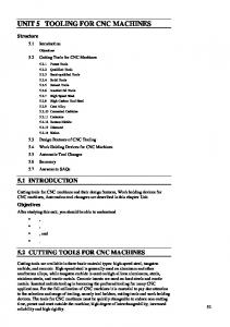
3. Applications The algorithm developed in the preceding section is used to create a user-defined cycle (G890) suitable for a Giddings & Lewis machining center, which is a horizontal milling machine equipped with a Numeripath 800-B CNC unit and an EMCO Vertical Machining Center equipped with a Sinumeric 840-D. Figure 2(a) and 2(b) give the details of such a cycle (G890) for both CNC control units, respectively. The parameters can be modified to suit a Fanuc control unit by changing parameter P1to be #1 and parameter P2 to be #2 and so on. After uploading the user-defined cycle (G890) software for the CNC unit, the software will be stored in CNC memory. The programmer and machine operator cannot see the subroutine or change it. The software contains all parameters and calculations needed for the machine movements. The programmer will only need to call this cycle and fill in the addresses, which is the same process as when using a canned cycle. However, the circular arrays must lie in the X-Y plane, and all the holes should be lying in a circular pattern. Each circular array should have its own pitch diameter and the holes should be equally distributed. The circular arrays should be equidistant from each other. The CNC control performs the positioning for the first hole in the first array; after that, the control will calculate the second hole in the first array and so on until the first array is completed. Then, the control will start the position for the first hole in the second array, followed by the second hole in the same array, and the control will continue until the end of the second array. The process is repeated for the remaining arrays. Figure (3) shows a part from a plate with holes lying in multiple circular patterns. The programs required for machining the circular patterns shown in Figure 3, are given in Figures 4(a) and 4(b) for a Numeripath800-B and Sinumeric 840-D, respectively. The input data are defined by the following: X = Drilling center on the X-axis for the first hole (P224) = 20 mm Y = Drilling center on the Y-axis for the first hole (P225) = 0 mm Z = Hole depth in the Z-direction (P226) = 10 mm E = Retract level in the Z-axis (P205) = 5 mm R = Approach level in the Z-axis (P218) = 5 mm I = Pitch diameter of the first circular array (P209) = 40 mm
(a)
(b) Fig. 2 (a) User defined cycle (G890) for drilling holes lying in a multiple circular patterns Suitable for Numericpath-800B Giddings Lewis (b) User defined cycle (G890) for drilling holes lying in a multiple circular patterns Suitable for Sinumeric 840-D
INTERNATIONAL JOURNAL OF PRECISION ENGINEERING AND MANUFACTURING Vol. 13, No. 10
OCTOBER 2012 / 1757
(a)
Fig. 3 Holes lying in a multiple Circular Patterns
(a)
(b)
(b) Fig. 4 (a) Part program for machining holes lying in a multiple circular patterns Suitable for Numericpath-800B Giddings Lewis (b) Part program for machining holes lying in a multiple circular patterns Suitable for Sinumeric 840-D
Fig. 5 (a) Apart from Screen Shot 3-D Simulation on Sinumeric 840-D that used the cycle (890) for machining the holes lying in multiple circular arrays patterns (b) Photograph for actual parts used the cycle (890) in machining the holes lying in a multiple circular patterns on Numeripath 800B Giddings & Lewis Machining Center
4. Conclusions J = Incremental radial distance between sequential pitch diameters (P210) = 20 mm W = Increment for increasing the number of holes in a sequential pitch (P223) = 40 mm U = Number of holes in the first array (P221) = 20 holes V = Number of multiple arrays (P222) = 20 arrays A = Angle of the circular array (P201) =360 degrees for a complete circle. Figure 5(a) shows a part from a screen shot on a Sinumeric 840D that used the cycle (890) for machining the holes lying in a multiple circular array pattern, and satisfactory results were obtained. Figure 5(b) shows a part on Orion Machining Center equipped with Numeripath800-B that used the cycle (890) for machining the holes lying in a multiple circular array pattern, and satisfactory results were obtained.
This paper describes an investigation to develop an easy, general programming algorithm in G-code for drilling holes lying in a multiple circular pattern. The presented algorithm can be used to create a user-defined cycle or a subroutine for any modern CNC unit such as the Sinumeric 840-C, Sinumeric 810D / 840D, Fagor 8070, Anilam5000M, Allen-Bradley Series-9, Giddings &LewisNumeripath 800-B, Fanuc-GE-21MB, HiedenhanTNC-426M or Acramatic-950. The new algorithm shows high efficiency in the part program establishment and offers the advantage of decreasing the encoding errors.
ACKNOWLEDGEMENT This Project was supported by King Saud University, Deanship of Scientific Research, College of Engineering Research Center.
1758 / OCTOBER 2012
INTERNATIONAL JOURNAL OF PRECISION ENGINEERING AND MANUFACTURING Vol. 13, No. 10
REFERENCES 1. Luggen, W. W., “Fundamental of Numerical Control,” Delmar Publishers, 2000. 2. Groover, M. P. and Zimmers, E. W., “CAD/CAM ComputerAided Design and Manufacturing,” Prentice-Hall Inc, 2003. 3. Gidding & Lewis, “Programming Instruction Manual for Numeripath 8000B,” 2004. 4. Siemens, “Programming Manual for Sinumeric 840-C,” 2005. 5. Siemens, “Programming Manual for Sinumeric 810D/840D,” 2010. 6. Cincinnati, “Programming Manual for Acramatic-950,” 2009. 7. Fanuc-GE, “Programming Manual for Fanuc-GE-21MB,” 2008. 8. Abbas, A. T., “Custom Macro in CNC Part Programs,” 7th, App. Mechanics & Mech. Engineering Conference, Technical Military College, pp. 150-159, 1996. 9. Abbas, A. T., “Enhanced CNC lathe capability by addition of a grinding spindle,” International Journal of Production Research, Vol. 41, No. 12, pp. 2699-2709, 2003. 10. Abbas, A. T., “A general algorithm for profiling and dressing of complicated shape grinding wheels,” Robotics and Computer Integrated Manufacturing, Vol. 20, No. 4, pp. 313-327, 2004. 11. Abbas, A. T., “A general algorithm for profiling and dressing grinding wheels when using a grinding spindle on a CNC lathe,” International Journal of Production Research, Vol. 42, No. 18, pp. 3995-4008, 2004. 12. Abbas, A. T. and Megahed, S. M., “A general algorithm for drilling holes lying in a matrix,” Robotics and Computer Integrated Manufacturing, Vol. 21, No. 3, pp. 235-239, 2005. 13. Abbas, A. T., Aly, M. F., and Hamza, K., “Optimum drilling path planning for a rectangular matrix of holes using ant colony optimisation,” International Journal of Production Research, Vol. 49, No. 19, pp. 5877-5891, 2010. 14. Islam, M. N., Rafi, N. H., and Charoon, P., “An Investigation into Effect of Canned Cycles on Drilled Hole Quality,” Proceedings of the World Congress on Engineering 2009, Vol. I, 2009.