tion-based advertising, mobile inventory management and mobile financial services. ... The best technique for location-finding is, of course, GPS (Global Positioning ... to users, such as in tracking field service engineers, or in tracking transport ... ing systems to achieve some degree of accuracy, such as in the software ...
Critical Analysis and Error Determination of Locating-finding Techniques in GSM WJ Buchanan Reader, School of Computing, 10 Colinton Road, Napier University, UK.
K A Raja Software Engineer, Justfone plc, Newton St. Boswell, UK.
J M Munoz Senior Lecturer, School of Computing, 10 Colinton Road, Napier University, UK.
Abstract: GPS is a well-established technique for location-finding, but mobile phone-based methods are generally less expensive to implement, and can give reasonable accuracies. These techniques can thus be useful to network operators in providing services based on geographical locations, and also to users. This paper reviews the main handset location techniques used within a GSM network, and critically appraises them. The main techniques covered include Cell-ID, E-CGI, TDOA, AOA, TOA, OTA and Timing Advance (TA). It also outlines a practical experiment in the UK in locating finding, which uses TA signal to locate the handset. The results show how an experiment can be conducted to determine the error in the location measurement. Keywords: Location-finding, GPS, Cell-ID, TDOA, AOA, TOA, OTD, Timing Advance. Biographical notes: WJ Buchanan is a Reader in the School of Computing at Napier University, and leads the Distributed Systems and Mobile Agents (DSMA) research group. He has a PhD and has written more than 20 academic books, and published over 50 research papers. KA Raja is a software engineer working at Justfone Limited. He gained a degree in Electronics and Communication Engineering in 1997 and an MSc. in Software Engineering in 2001. He is currently completing an MPhil in locationfinding techniques. His main interest are in wireless communication networks and wireless application solutions. J M Munoz is a Senior Lecturer at Napier University. He obtained his PhD in Computational Physics in 1981, and worked in industry developing system and communications software, before joining the University in 1988. Current research interests include congestion control and network security, and is a member of the DSMA research group.
1 Introduction Many mobile phone network providers are investigating new methods of generating new income, and location-finding has great potential in supporting location-based services [1]. This might include location-based advertising, mobile inventory management and mobile financial services. There is, obviously, constraints to these technologies, such as changes in business strategies, investment risk, limitations in mobile devices, networking problems, infrastructure constraints, security concerns, and a general user distrust of mobile applications [2]. This paper focuses on the main methods that can be used to provide location information, especially for the GSM network. The best technique for location-finding is, of course, GPS (Global Positioning System) system which has a good accuracy for virtually any area of the world. Unfortunately, it can be relatively expensive to implement, and does not give good coverage around and within buildings. Users can thus be tracked in an open environment, but their trace may be lost as soon as they enter a building, or if the path between them and the GPS satellites is obstructed. Mobile phone techniques, on the other hand, are generally less expensive to implement, and can give reasonable accuracies. These techniques
1
can thus be useful to network operators in providing services based on geographical locations, and also to users, such as in tracking field service engineers, or in tracking transport services [1]. A major worry in mobile communications, though, is that users often distrust the security of mobile devices [2]. For this, a context-aware mobile information system (CAMIS) has been developed [3], which uses a nonintrusive Push to deliver information to mobile users using cell-broadcast technology. Generally, positioning technologies can be defined in terms of:
Performance. This is based on the accuracy of the positioning method that gives different levels of accuracy and hence aims at different market sectors. For example, fleet managers do not require a high level of accuracy, so this method can simply find the nearest antenna to the device. However, emergency services, such as mountain rescue or ambulance services, are likely to require more accuracy, such as determining the distance that the device is away from several antennas. Complexity. Sometimes combing and deploying two or more location technologies give results that are more accurate. These positioning technologies can be grouped under complexity, and are commonly known as hybrid. Implementations requirements. Some implementations require extra implementations in the existing systems to achieve some degree of accuracy, such as in the software requirements of the handsets, or in the hardware requirements of the mobile network. Investment. This is a major factor, and it depends on the amount of additional services that the network can provide for in the future, and their required level of accuracy.
The calculation of location can either be done by the handset (in the handset-based mode), or by the network (in the handset-assisted mode). In the handset-assisted mode, the handset makes measurements, and reports these back to the network as a Network Measurement Report (NMR), which calculates the handset position. These modes are shown in Figure 1.
Handset
Network Assistance
Position Calc Function
Handset-based mode Position (x,y)
Position (x,y)
Assistance Handset-assisted mode Measurement
Position Calc Function
Position (x,y)
Figure 1: Handset based mode
2 Location Estimation Techniques The main techniques used to estimate the location of a mobile handset include: GPS (Global Positioning System), Cell-ID (Cell Identity), AOA (Angle of Arrival), TOA (Time-of-arrival), OTD (Observed Time Difference), A-GPS (Assisted – Global Positioning System), E-OTD (Enhanced - Observed Time Difference). These are outlined in this section.
2
2.1
GPS (Global Positioning System)
The application of GPS expands and is now becoming embedded into many electronic devices [4]. It is a highly location-finding accurate method, but is often expensive to implement on a wide-scale basis. It also has limited coverage in urban areas, especially within buildings or near obstructions. As an alternative, mobile phone-based location-finding is an inexpensive method for location-finding, as it has wide-scale coverage, along with inexpensive handsets. 2.2
Cell-ID (Cell Identity)
The most basic location-finding method used in a GSM network are based on cell identification (CellID). This is a network-based positioning method, which uses the cell that the handset is registered to. This information is available in the network, and at the handset. The Cell-ID is then converted to a geographic position using the knowledge of the operator’s network, such as coverage database at the serving mobile location centre (SMLC). The accuracy level thus generally depends on the cell size, but may also depend on other factors such as the wireless network type (GSM or PCS), cell type (omnidirectional or sectored), cell kind (macro cells – large-scale cells - or pico cells – small-scale cells), and so on. It has the advantage that it supports every legacy handset and also roaming subscribers. A sectored cell uses a number of antennas in the cell, and these provide sector information. The larger the number of sectors, the more accurate the location of the device will be. For example, a three-antenna cell, gives a sector coverage of 120° for each sector. The accuracy will thus be ±60° (Figure 2). When a handset is registered to an omni-directional cell, the location of the handset becomes the exact location of the mast, that is, centre of the cell and the coverage area (cell size) of that mast becomes the accuracy level (Figure 3). In the case of sectored cell, the handset’s location is calculated using mathematical algorithms. The accuracy level in GSM1800 or GSM1900 (PCS) networks is higher compared to accuracy level in GSM900 network, where the maximum cell size is around 35km. It also varies from location to location, such as in rural, suburban and urban areas.
Figure 2: Cell-ID
3
Figure 3: Cell site with sector
2.3
E-CGI (Enhanced-Cell Global Identity)
With E-Cell ID, the handset makes measurements of its operating conditions, and sends these to the network for hand-over decisions. This NMR contains the estimated power level at the handset from the serving cell, and also from neighbour cells. The power level measured at the handset can then be used to estimate the location, based upon simple propagation models and/or network planning tools. Similar techniques can be used using the Timing Advance (TA) signal parameter, instead of the NMR, and the TA is a measure of the handset range from BTS1 (Base Transceiver Station), and has a resolution of around 550m and improves the accuracy level in larger (omni-directional and sectored) cells, as in GSM 900. With TA, the handset registers with at least three BTSs which send out a timing signal, for which the handset sends back a result to the network for a position calculation. 2.4
AOA (Angle of Arrival)
AOA is based on a classic radio direction finding technique where a highly directional antenna (electronically steered array) determines a line-of-bearing between the handset and the BTS. The relative angles can then be calculated using the phase differences across the array or by measuring the power density across the array. Once the measurement has been made, normally from at least three BTSs (Figure 4), the location can be calculated by simple triangulation. Unfortunately, this technique requires a line-of-sight connection between the handset and the BTS, as reflected signals will provide a false line-of-bearing. Thus, as the GSM network does not necessarily make a line-of-sight connection, this technique is often used in conjunction with another location technique.
1
Base Transceiver Station (BTS) is a mast with antenna 4
Figure 4: AOA
2.5 TOA (Time-of-arrival) and TDOA (Time Difference of Arrival) TOA works by the handset bouncing a signal back off the BTSs, or vice-versa. Since radio waves travel at the speed of light (c), the distance (d) between the handset and BTS can be estimated from the transmission delay, that is, half the time delay between transmitting and receiving the signal. This, however, locates the handset as being on a circle with a radius d, with the BTS at the centre of the circle. If the estimate is made from three BTSs, there will be three circles that intersect at the handset, as shown in Figure 5. The TDOA technique is time-based and similar to TOA. It works by either measuring the relative arrival time in the handset of signals transmitted from three BTSs at the same time; or measuring relative arrival time transmitted by the handset at three BTSs. The difference of arrival time defines a hyperbola, with the loci at the two BTSs. As three BTSs are used, there are three sets of time differences which creates three hyperbolic equations that define a single solution. TDOA is sometimes preferred to TOA as, in most implementations; there is less data to be exchanged over the wireless connection, although precise synchronisation of BTSs is required for this technique to work. In case additional accuracy is required, a serving BTS instructs the handset to hand-off, which causes the handset to transmit a new registration message. This registration message gives the BTS a new set of data to make a second estimate. 2.6
A-GPS (Assisted – Global Positioning System)
Like E-OTD, A-GPS is also a time-based technique in which the handset measures the arrival time of signals transmitted from three or more GPS satellites (Figure 6). In general, the information decoded by the GPS receiver from the satellites is transmitted to the handset through the radio network, bringing improvements for the time-to-first-fix (which is the initial time for the first location measurement) and battery life – as the handset no longer needs to search for and decode the signals from each available satellite. Removing the need to decode the satellite signals also enables detection and TOA estimation over multiple parts, which improves sensitivity. This allows A-GPS to provide position estimates under foliage, within cars, in most outside environments and many indoor environments. A-GPS also provides good vertical accuracy and velocity estimates. Signals of GPS assistance data to the handset may take 10 seconds, but, once received by the handset, assistance data is useful for up to four hours.
5
Figure 5: TDOA
Figure 6: A-GPS
2.7
E-OTD (Enhanced-Observed Time Difference)
In this time-based technique, the handset measures the arrival time of signals that are transmitted from at least three or more BTSs (Figure 7). This time measurement capability of E-OTD is a new function on handsets. In the handset-assisted mode, the timing measurements made by the handset are then transferred to the Serving Mobile Location Centre (SMLC) using standardised LCS signalling. These measurements are then related to the distance from each BTS to the handset and the position of the handset is estimated using triangulation. In handset-based mode, the position calculation function is in the handset, and the position is returned to the SMLC. The position of each BTS must be accurately known to perform triangulation, and estimate the position of the handset. Also, the transmission times of each BTS must be accurately known. In a GSM network, which is not synchronised, the BTS transmission time must be measured using a network of Location Measurement Units (LMUs). These are essentially modified mobile devices, optionally with a GPS receiver, placed in a fixed geographical position, with the capability to perform E-OTD measurements, and return them to the SMLC. The general accuracy 6
of E-OTD is defined in Table 1. Its accuracy is generally dependent on cell density, cell plan, multipath, interference, noise, LMU performance, and cell site position accuracy. It has the advantage that it does not degrade much indoors, and it performs well in high BTSs density areas. Conversely, its performance degrades in areas with low BTSs density. 2.8
Signal Strength
As GSM networks were developed, the signal strength location technique was one of the first techniques to be proposed, as it was the simplest to implement. It uses the signal strength (received power level) in the handset transmitted from the serving BTS to estimate the distance. If the transmitting power of the BTS, and the receiving power in the handset are known, then, using a path loss equation, a distance (d) from each other can easily be calculated. Thus, measuring distance in this way, with at least three BTSs, gives three circles. A handset location can then be easily calculated by the approximate intersection of these circles of known radius (d) by using least squares to minimise error (Figure 8). 2.9
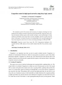
Hybrid
Hybrid technique uses more than one type of location-finding technology to improve accuracy. Typical examples are AOA with TOA (Figure 9), AOA with TDOA, signal strength with TA, and so on. Several researchers suggest a TDOA-TOA hybrid would improve location estimate accuracy.
Figure 7: E-OTD Table 1: Accuracy of various technologies [5]
Technology Cell ID
Rural 1-35km Typical: 15km
Suburban 1-10km Typical: 5km
Urban Macrocells: 500m-5km Typical: 2km
E-CGI
250m-35km
250-2.5km
Microcells: 50-500m Typical: 200m 50-550m
E-OTD A-GPS
50m-150m 10m
50-150m 10-20m
50-150m 10-100m
7
Indoor 10m-50m (if pico cells are used)
Highly variable Good Variable
Figure 8: Intersection between three circles of known radius
Figure 9: Hybrid technique
8
3
Critical Analysis
This section provides a short critical analysis of the main techniques. 3.1
Signal Strength
There are fundamental problems associated with the signal strength measurements, which are commonly used in Enhanced Cell-ID method and in signal Strength method. These include:
3.2
Fading2. The fading profile of received power requires that the mobile device is not stationary, and that some form of averaging is required. It is suggests that long-term median averaging can yield estimates that vary by as little as 0.5dB with individual estimates varying by 40dB. Signal strength. The signal strength measurements must be converted to distance measurements. Several researchers have proposed qualifying each BTS with a contour map of signal strength measurements, however with the large number of BTSs, this would now be unrealistic. Recently Hata [6] has derived a widely accepted empirical formulae from actual data, however, these do not take into account local variations caused by the actual terrain. Main Obstacles to Location Estimation
There are several key obstacles associated with location estimation which will have to be overcome. Interference, of course, has an important role in the quality of the location-service. This can take the form of multiple paths of the radio signal, or from other radio devices. These can also be affected by local scatter patterns, which are caused by local geographical objects, such as buildings and trees. 3.3
Hearability of Remote BTSs
In most techniques, non-serving BTSs3 are involved. The hearability of signals to, or from, these BTSs may cause some measurements to be impractical, when the handset is close to its serving BTS. This typically occurs in the GSM handsets with power-controlled communications, which causes the SIR4 (for the remote signal) to be high. It may thus be impossible to collect the required measurements from the remote BTS in a short enough time. For this, Motorola propose a power-up function in the handset [7], whereas Cedervall proposes slotted transmission at the BTS [8] which uses a TOA approach and simulates location accuracies to less than 125m for 80% of the time. Both techniques have a significant effect on the capacity of the network that may be worth further studying. Another important technique to consider is interference cancellation, whereby known signals that are present are removed from the received signal, thus reducing the apparent SIR. 3.4
Multi-path Conditions
Multi-path effects are caused by the air interface and local scatterers, such as reflections off geographical features like buildings, trees, that results in a received signal being made up of several different copies of the same transmitted signal, at different time delays, magnitude and phase. In modern systems, the communication channel is estimated and a RAKE receiver 5 can be implemented to capture these rays. Multi-path will have an effect on Angle of Arrival (AOA) measurements (particularly at the handset) as a large angle spread may be observed at the receiver. Typical values are 360 for indoor, 20 for urban and 1 for rural environments [9]. 3.5
Non-Line-of-Sight (NLOS) Conditions
The problem of non-line-of-sight (NLOS) communication is fundamental, as timing, signal strength, 2
3 4 5
Fading involves varying signal strengths such as with a contour map that can be made from varying signal strengths for each base station These are base stations that your mobile can see but not registered with. SIR defines the ratio between the strength of the signal and the strength of the interference. A RAKE receiver is a device invented by Price and Green in 1958 where the multiple signals appear as fingers of a garden rake head. 9
and, especially AOA information, will be inaccurate, as the path is not a straight one. Results of a recent a study indicates change in propagation distances of 400 to 700m will be typical for a handset experiencing NLOS conditions. In TDOA, timing errors may cancel out to a certain degree assuming similar NLOS properties to each BS. It seems feasible that the NLOS propagation errors may be predictable by analysing measurement statistics. Certainly, to simulate a realistic scenario, a dynamic LOS/NLOS channel must be modelled. 3.6
Geometric Dilution of Precision (GDOP)
In certain situations, GDOP will have a significant effect on the accuracy of the system, particularly in highway cells where the BTS arrangement may be linear. Pent et al [10] and Lee [11] propose methods to measure the GDOP and demonstrate the effect on their simulated results. In theory, it will be possible to reject certain measurements using GDOP analysis.
4
Experiment
The purpose of this section is to define an experiment for one of the location technologies discussed earlier, so that its expected and actual performance can be assessed against theory, field trials and published material. This experiment was carried out using GSM 900 mobile network and it makes exclusive use of a GSM parameter - Timing Advance - which is only available in the handset and used by serving BTS to receive timing frame from the handheld, on-time. 4.1
Timing Advance (TA)
The radio interface in GSM uses a combination between frequency (FDMA) and time (TDMA) multiplexing. The frequency division in GSM 900 allocates 125 frequencies in each direction for GSM. The basic parameters are:
Uplink6 frequencies are between 890 and 915MHz. Downlink7 frequencies are between 935 and 960MHz. Carrier frequencies are separated with 200 kHz on each side. These frequencies are allocated in pairs, so that each uplink/downlink pair is separated with exactly 45 MHz. Each of the carrier frequencies are divided into eight logical channels, using TDMA, and a TDMA frame contains one time-frame from each of the eight channels, and lasts 4.615 ms. Time-frames from each channel lasts 0.577 ms. Total bit-rate for all eight channels is 270.833 Kbit/s, whereas the bit-rate for each channel is 22.8 Kbit/s.
In order to get the TDMA scheme to work, the time frames from each mobile station must be synchronized when received by the BTS. The TA implements synchronization [12], and the degree of synchronization is measured by the BTS on the uplink. This is achieved by checking the position of the training sequence, which is mandatory in all frames transmitted from the handheld. From this, the BTS calculates the TA and sends it back to the handset in the first downlink transmission. From the TA value received from the BTS, the handset can determine when to send the frame, so that it can arrive at the BTS in synchronism. The values of the TA is continuously calculated and transmitted to the handset during the lifetime of a connection. The TA can vary between 0 to 233s, and are coded by six bits, where [12] where a zero is defined as no timing-advance, and 63 as a maximum timing advance. This gives a time-difference of 233/63 = 3.70s. These measurements of TA can be used to calculate distance directly. As one bit of the TA represents a difference of 3.70s of the signal BTS - handset - BTS, and the refraction index of air is approximately 1 [14], the distance per bit of TA is: 6 7
Uplink is handheld to BTS Downlink is BTS to handheld 10
3.70s.c.
1 1 3.70.3 108. 550m 2 2
(4.1) Since the TA is rounded to the nearest bit-period during calculation, the actual BTS-MS distance, d, is: 1 1 550.TA d 500.TA ,TA 0 2 2
(4.2) where 0