University of Twente, Faculty of Electrical Engineering, Mathematics and Computer ... tennas for radio astronomy [3], that impose stringent SFDR requirements to the APLs. To .... ductor DSC-710) with an RF spectrum analyzer (Agilent MXA N9020A) at ... DR (d. B .Hz. 1/2. ) Modulating frequency (GHz). Push-pull APL. 18 dB.
Enhancement of Multioctave Dynamic Range in a Push-Pull Modulated Analog Photonic Link D.A.I. Marpaung, C.G.H. Roeloffzen and W. van Etten University of Twente, Faculty of Electrical Engineering, Mathematics and Computer Science, Telecommunication Engineering group, P.O.Box 217, 7500 AE Enschede, The Netherlands We demonstrate an analog photonic link with a high multioctave spurious-free dynamic range (SFDR) using a push-pull modulation technique of laser diodes combined with a balanced detection scheme. SFDR enhancements ranging from 5 dB to 18 dB, relative to the case of a single arm link, have been obtained in a frequency range of 2.5 GHz to 3.2 GHz.
Introduction These past few years, there have been numerous research efforts concentrated on the spurious free dynamic range (SFDR) enhancement of analog photonic links (APLs). These efforts are driven by various applications, such as military radars [1] and phased-array antennas for radio astronomy [3], that impose stringent SFDR requirements to the APLs. To date, most efforts to increase the SFDR have been directed to externally-modulated APLs rather than directly modulated ones [2]. This, to some extent, is attributed to the fact that external modulation offers chirp-free operation and a higher modulation bandwidth compared to direct modulation. However, for applications in which a large number of APLs are required, employing external modulators might become too costly. In this case, directly modulated lasers (DMLs) are still very much preferred due to their low cost and simple operation. These DMLs, nevertheless, should provide sufficiently large SFDR. One of the main limitations of DMLs is the high second-order intermodulation distortion (IMD2) [2]. This prevents them to be implemented in broadband systems in which the signal has a bandwidth of more than one octave (i.e. multioctave). A solution to this problem is to suppress the IMD2 using a technique that combines push-pull modulation of DMLs with a balanced detection scheme [1, 3]. Using this technique, we recently reported one of the highest SFDR ever achieved with DMLs, shown at the frequency of 2.5 GHz [3]. In this paper, we optimize our system to operate in an extended frequency range beyond 2.5 GHz.
Push-Pull Modulated APL Ideally, the push-pull modulated APL consists of a 180o hybrid coupler, a pair of DMLs and a balanced photodetector (BPD) [3]. The 180o hybrid coupler supplies antiphase RF signals to the DMLs such that they are modulated in a push-pull manner. This results in a pair of optical signals with a 180o (RF modulation) phase difference. Providing that the optical fibers lengths to the BPD inputs are matched, differential detection of these antiphase optical signals will yield to additive photocurrents at the BPD output. Supposing
Laser Controller
Signal Generator
ILX Lightwave MENUS
INPUT Frequency
LDC-3724
12.500 000 000 00 GHz
3.00 dBm
LASER DIODE CONTROLLER
TEC
ADJUST
LASER
EXT INPUT 1
Mode
C
AMPLITUDE
FREQUENCY
mA
Amplitude
EXT INPUT 2
GPIB
TEC DISPLAY
POWER
MSG
STATUS
7
8
9
4
5
6
1
2
LASER DISPLAY
LOCAL
LF OUTPUT
TEC MODE
PARAMETER
LASER MODE
RANGE
MOD
200 mA 500 mA
EXTERNAL
RF OUTPUT
3
0
Preset
DML 2 180 Hybrid
Combiner
MXA
VODL
o
Center Freq 5.00000000 GHz Input : RF
MENUS Frequency
3.00 dBm
MARKER
UTILITY
LXI
Auto Tune
-90
Start Freq Enter
7
8
9
4
5
6
1
2
3
-100
Stop Freq
-120
0
CF Step
DML 1
RF att.
EXT INPUT 1
Mode
AMPLITUDE
12.500 000 000 00 GHz
ANALYZER SETUP
Frequency
Center Freq
-110
Res BW 30 Hz
FREQUENCY
1 2 3 4
-70
-80
MSG
INPUT
Avg Type : Log-Pwr Atten : 10 dB
Ref -30.00 dBm -60
Amplitude
VBW 30 Hz
Span 10 kHz
RF Input
STATUS
RF Spectrum Analyzer
EXT INPUT 2
BPD
LF OUTPUT
ILX Lightwave 7
MSG
STATUS
8
4
5
1
2
LDC-3724
LASER DIODE CONTROLLER
9 6
TEC
RF OUTPUT
3
ADJUST
LASER C
mA
0
Preset
GPIB
TEC DISPLAY
LASER DISPLAY
LOCAL
Signal Generator
POWER
TEC MODE
PARAMETER
LASER MODE
RANGE 200 mA 500 mA
MOD EXTERNAL
Laser Controller
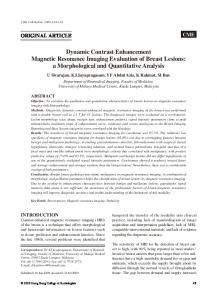
Figure 1: Schematic of the realized push-pull modulated APL. DML: directly modulated laser, VODL: variable optical delay line, BPD: balanced photodetector. that the DMLs are identical, perfect amplitude matching of the antiphase optical signals can be achieved. In this case, the output RF signal of the push-pull APL will be 6 dB higher compared to the case of a single arm APL (which can be obtained by means of disconnecting one of the optical fibers to the BPD) and the IMD2 at the BPD output will be completely suppressed. This suppression will, in turn, increase the link multioctave (i.e. broadband) SFDR.
Measurement Setup The realized push-pull APL is shown in Figure 1. A two-tone measurement was carried out to characterize the distortion (and subsequently the SFDR) of this APL. We use a network analyzer (Agilent N5230A ) and a vector signal generator (Agilent E4438C) to supply a pair of RF tones to the DMLs via a 2:1 combiner and a 180o hybrid coupler. The insertion loss of the combiner and the hybrid coupler amounts to 10 dB. The tones are 10 MHz apart and their center frequency, fc , was varied from 1 GHz to 4 GHz with a step of 100 MHz. The DMLs are 1310 nm DFB lasers from Fitel with 20 mW maximum output optical power and 4 GHz modulation bandwidth. The DMLs bias currents are adjusted with a pair of laser diode controllers (ILX Lightwave LDC 3722 and LDC 3724). Since DML1 shows higher second-order nonlinearity relative to DML2 [3], an RF attenuator is placed in the lower arm of the APL (Figure 1) to attenuate the RF power supplied to this laser and subsequently to match the IMD2 amplitudes at the upper and the lower arms. Because the IMD2 suppression is highly sensitive to phase matching, a variable optical delay line (VODL) is used to correct the phase imbalances of the optical signals due to the length mismatch. The fundamental, IMD2 and the third order intermodulation distortion (IMD3) powers are measured at the output of the BPD (Discovery Semiconductor DSC-710) with an RF spectrum analyzer (Agilent MXA N9020A) at frequencies of fc + 5 MHz , 2 fc and fc + 15 MHz, respectively.
Measurement Results To determine the optimum operating currents of the DMLs, the injection current to each laser is varied from 40 mA to 85 mA and, for every bias point, the IMD3 power of the individual laser is measured. For this characterization, the input RF power supplied to the
-50
-60 Selected bias current
1 GHz
-55
Selected bias current
2 GHz
= 55 mA
IMD3 power (dBm)
IMD3 power (dBm)
-60 3 GHz
-65
-70 4 GHz
-75
= 73 mA
-65
-80
-70
1 GHz
-75
2 GHz
-80
-85 3 GHz
-90
-85
-90
4 GHz
-95
40
45
50
55
60
65
70
75
80
85
40
45
50
Bias Current (mA)
55
60
65
70
75
80
85
Bias current (mA)
(a)
(b)
Figure 2: IMD3 power as a function of laser injection current for (a) DML1 and (b) DML2. -27
-65
-70
IMD2 Power (dBm)
Push-pull APL
DML2
-33 DML1
S
21
(dB)
-30
-36 Single-arm APLs
DML2 Single-arm APLs
-80 DML1
-85 Push-pull APL
-90
-39 1.0
-75
-95
1.5
2.0
2.5
3.0
3.5
Modulating frequency (GHz)
(a)
4.0
1.0
1.5
2.0
2.5
3.0
3.5
4.0
Modulating frequency (GHz)
(b)
Figure 3: (a) Fundamental signal and (b) IMD2 powers as functions of the modulation frequency. combiner is set at 9 dBm per tone. The characterization results for DML1 and DML2 are shown in Figures 2(a) and 2(b), respectively. Here, we have set the modulating frequency as a parameter. Our aim is to determine the bias currents where the IMD3 powers are low in a wide range of modulation frequency, from 1 GHz to 4 GHz. As evident from Figure 2, these optimum bias currents are 55 mA and 73 mA for DML1 and DML2, respectively. Having selected the DMLs bias currents, we optimize the system by adjusting the RF attenuator and the VODL with the objective of obtaining maximum IMD2 suppressions for a wide range of modulating frequencies. The optimum RF attenuation is found to be 4 dB and the maximum IMD2 suppresion related to this attenuation is limited to 25 dB. Higher suppressions can be obtained by using an attenuator with a better step resolution. Ideally, the way to correct the phase imbalances in the system is to observe - in real time - the IMD2 powers as the VODL is adjusted to obtain maximum IMD2 suppresssions. However, this type of measurement requires a synchronized frequency sweeping for modulation and detection at two different frequency ranges. For example, if the the modulation frequency is fc , the detection should be done at 2 fc . Due to the limitation in our measurement setup, this type of measurement was unavailable. Thus, we optimize the system by means of adjusting the VODL while observing the fundamental signal power instead of the IMD2 power.
The optimum setting is thus determined by the widest range of modulation frequency in which maximum signal enhancement is achieved. This is illustrated in Figure 3(a). A maximum signal enhancement of 6 dB, relative to the case of single-arm APLs, is obtained at a modulation frequency range of 2 GHz to 3.5 GHz. With this arrangement, the IMD2 power in the push-pull configuration is measured. The result is shown in Figure 3(b). The suppression is achieved in the modulation frequency range of 2.5 GHz Figure 4: The measured multioctave SFDR of to 3.2 GHz, shown as a grey area in Figure 3(b). A maximum suppression of 25 dB is the push-pull and the single-arm APLs. obtained at the frequency of 2.81 GHz. The overall suppression can be increased by using an attenuator with finer attenuation steps. In this frequency range, the SFDR of the push-pull and the single-arm APLs is characterized. Here, we use the definition of SFDR to be the signal-to-noise ratio at the input RF power where the intermodulation distortion power (IMD) is equal to the noise power [2]. As evident from Figure 4, the push-pull APL shows improved IMD2-SFDR, over a considerably wide frequency range, compared to the single-arm APLs. A maximum improvement of 18 dB is achieved at the modulation frequency of 2.81 GHz. At this frequency, the IMD2-SFDR and the IMD3-SFDR of the push-pull APL are 107 dB.Hz1/2 and 118 dB.Hz2/3 , respectively. In contrast to the single arm APLs (IMD2-SFDR = 90 dB.Hz1/2 , IMD3-SFDR = 117 dB.Hz2/3 ), the push-pull APL provides more comparable sub-octave and multioctave SFDR values. This makes the implementation of this type of APL in broadband applications very attractive. 110
105
IMD2-SFDR (dB.Hz
1/2
)
Push-pull APL
100
18 dB
95
DML2
90
85
2.5
DML1
Single-arm APLs
2.6
2.7
2.8
2.9
3.0
3.1
3.2
Modulating frequency (GHz)
Conclusions Measurement results of a push-pull modulated APL have been presented. The link shows improved IMD2-SFDR characteristic relative to the conventional single-arm APLs. Multioctave performance has been achieved at the frequency range of 2.5 GHz to 3.2 GHz.
Acknowledgements This work is supported by the Dutch Ministry of Economic Affairs through the PACMAN project, SenterNovem project number TSIT 3049.
References [1] S. Pappert, C. Sun, R. Orazi, and T. Weiner, “Microwave fiber optic links for shipboard antenna applications”, Proc. 2000 IEEE Int. Conf. Phased Array Systems and Technology, pp. 345-348, 2000. [2] C. H. Cox, E. I. Ackerman, G. E. Betts and J. L. Prince “Limits and performance of RF-over-fiber links and their impact on device design ,” IEEE Trans. Microwave Theory & Tech., vol. 54, no. 2, pp. 906-920, February 2006. [3] D. A. I. Marpaung, C. G. H. Roeloffzen and W. van. Etten, “A Broadband High Dynamic Range Analog Photonic Link using Push-Pull Directly Modulated Semiconductor Lasers,” IEEE/MTT-S International Microwave Symposium, pp. 507–510, 15–20 June 2008.