Enhancing Collaborative Synchronous UML Modelling with Fine-grained Versioning of Software Artefacts A. De Lucia*, F. Fasano*, G. Scanniello†, G. Tortora*
[email protected],
[email protected],
[email protected],
[email protected] *
Dipartimento di Matematica e Informatica - Università di Salerno Via Ponte don Melillo - 84084 Fisciano (SA) - Italy
†
Dipartimento di Matematica e Informatica - Università della Basilicata Viale dell’Ateneo, 10 – Macchia Romana – 85100 – Potenza - Italy
Abstract Software development teams are composed of people with different knowledge and skills, who contribute to a project from often widely dispersed locations. Software development in geographically distributed environments creates software engineering challenges due to the interaction among members of distributed teams and the management of consistency and concurrency among project artefacts. In this paper we propose STEVE (Synchronous collaborative modelling Tool Enhanced with VErsioning management) a collaborative tool supporting distributed UML modelling of software systems. The tool provides a communication infrastructure enabling the concurrent editing of the same UML diagram at the same time by distributed developers. Complex UML diagrams are decomposed and managed in a fine-grained hierarchy of sub-artefacts, thus providing change and configuration management functionalities for both the diagram and the graphical objects. Thus, software predefined diagram components can be consistently reused and shared across different diagrams of a given project.
1. Introduction The phases of a process development model typically involve the interaction of specialists in different geographical settings and from different fields, who must communicate their decisions and coordinate their activities. Therefore, software organisations require new paradigms and tools to reduce development costs,
1
enhance availability of the development staff, improve the flexibility to allow inhouse staff and adapt quickly to volatile business needs. Unfortunately, software development in geographically distributed environments often creates software engineering challenges due to the impact of temporal, geographical, and sociocultural differences. In such a scenario the main issue becomes the interaction among members of distributed teams as well as the management of consistency and concurrency among project artefacts. Computer Supported Collaborative Work (CSCW) research has focused on supporting collaboration in many applications including visual modelling [17]. This resulted in the development of several collaborative synchronous visual modelling environments [9][12][16] that enable geographically dispersed developers to edit and discuss about the same diagram. Visual and diagrammatic representations provide important tools for describing, reasoning, and communicating. Indeed, visual languages can potentially improve productivity in different application domains since they provide means to easily capture and model difficult concepts underlying the structure of a problem, and facilitate finding a possible solution. In the software engineering domain they are widely employed to support the phases of the development process, such as requirements specification, analysis, and design. In particular, UML (Unified Modelling Language) [30] includes a set of visual languages for modelling both software systems and business processes. However, collaborative modelling environments usually do not provide concurrent versioning functionalities. In some cases they provide simple functionalities for versioning diagrams at file level [24][29]. This is mainly due to the fact that the file based approach is typically adopted by the most common concurrent versioning tools [2][11][32]. This coarse-grained management of the diagrams does not enable the reuse of diagram elements across projects. Even when diagram elements sharing is allowed [3][24], the software engineer cannot reuse diagram elements among artefacts of different types. As an example, the description of a use case provided in the use case diagram cannot be reused within the software requirements specification document. This can cause consistency problems each time the element is changed in the modelling tool and/or in the high level documentation. This consideration suggests the usefulness of a fine-grained management of software artefacts, where each single element of a document or a diagram is managed as a different entity and versioning is provided for both the atomic entity (e.g., a use case or its description) and the entities it is contained in (e.g., a diagram or a requirements analysis document). The fine-grained versioning management approach has been applied to high level software documents [7][25][27], hypermedia documents [20], and source code [10]. Recently, it has also been applied to UML diagram elements [28]. However, till now these fine-grained versioning systems have not been integrated with collaborative synchronous visual modelling environments. In this paper we propose STEVE (Synchronous modelling Tool Enhanced with VErsioning management) a cooperative UML-based synchronous modelling environment. A communication infrastructure is provided to enable concurrent
2
editing of the same diagram at the same time by distributed developers. STEVE is integrated in ADAMS [13][14], a Process Support System that provides finegrained management of software artefacts [7]. Complex UML diagrams are decomposed and managed in a fine-grained hierarchy of sub-artefacts, thus providing change and configuration management functionalities for both the diagram and the contained graphical objects. The reminder of the paper is organised as follows. Section 2 discusses related work on cooperative development support, while Section 3 presents an overview of STEVE. Section 4 presents its architecture and collaborative functionality, while Section 5 discusses how it has been enhanced with fine-grained artefact management. Section 6 concludes the paper. 2. Related Work The problem of providing geographically distributed software engineers with collaborative modelling tools is long dated. Dewan and Riedl [15] demonstrate the application of concurrent software engineering to different software development tasks to show concretely the potential for increasing the effectiveness of teams working together. They also present Flecse (Flexible Environment for Collaborative Software Engineering), an environment supporting concurrent software engineering. Grundy et al. [18] propose SPE (Smart Programming Environment), an Integrated Software Development Environment providing multiple textual and graphical views for constructing programs in an object-oriented language. The authors also present C-SPE an extension of SPE to support the synchronous and asynchronous collaborative object-oriented development. In [19] a PSS is presented that includes several visual tools for collaborative software development. The focus is in particular on the collaborative definition of process models to enable the coordination of the work of software engineers within the proposed environment. The system also supports version control of the process models. The REDUCE (REal-time Distributed Unconstrained Cooperative Editing) project [31] aims to research, develop, and apply innovative technologies for consistency maintenance and concurrency control in real-time collaborative editing systems. Under the REDUCE project collaborative text, graphics and programming systems have been researched. The project results have been applied in GRACE [8], a prototype for collaborative visual editing. Many UML tools provide version control and/or collaborative functionality. For instance, Rosetta [16] is a light-weight tool for web-based collaborative development of UML diagrams; however it does not provide versioning or reuse functionalities. Borland Together [3] and MagicDraw [24] provide a Teamwork solution enabling versioning of UML diagrams, and reuse of components across the project, but real-time concurrent modelling functionalities are not provided. iServer [22] proposes a UML solution by enabling Microsoft Visio [26] to behave as a
3
multi-user, repository-based cooperative modelling environment even if versioning is not provided. Lozano [23] has proposed DArgoUML, a Distributed version of ArgoUML [1], which includes a consistency maintenance framework based on software modelling knowledge. The tool is also able to detect different types of conflicts based on the different level of inconsistency they generate, but real-time modelling is not supported. Finally, the Enterprise Edition of Poseidon [29] features a client-server architecture that enables collaborative modelling. The project itself is managed and stored at the server, while modifications of the model by a client are deployed to all affected clients immediately. Features, like locking parts of the model for exclusive use and conflict checking are also included. Konesa [21] (initially known as Cittera) is a UML-based modelling tool providing real-time collaboration, version control, and an audit log that enables rollback to previous model versions. Users can create concurrent versions of a model, and the system can highlight the differences between those versions. Unfortunately, even if locking is at element level, in Poseidon and Konesa versioning management is at a coarsegrain level, as the tool maintains different versions of the same diagram and not different versions of the same element. Moreover, even if these tools allow model components to be reused across the project, they are not integrated into an artefact management system, thus sharing components with high level documentation is not possible. Boulila et al. [5] focuses on the specific problem of distributed brainstorming and the construction of UML models of software through successive distributed teamwork meetings. In particular, the authors investigate the issues in designing a unified framework based on CSCW concepts and Software Engineering to support concurrent Object- Oriented software analysis and design phases [4]. The authors also present D-UML (Distributed UML) [6] a Java implementation of the DMeeting framework, based on a Distributed MVC (Model-View-Controller) pattern. The Model resides in the Meeting object, and can be shared across a number of views composing the DUML groupware. Another approach to cooperative and real-time diagram modelling support consists of UML diagramming tools using an E-whiteboard, pen-based sketching interface to support collaborative design, including free-hand annotations and handwritten text [9][12]. In all these approaches the focus is only on collaborative modelling rather then on version control. Conversely, Odyssey-VCS [28] is a version control system providing fine-grained versioning of UML diagrams. However, even if it implements an algorithm to merge and detect conflicts between two different versions of the same UML diagram element, it is not integrated with a synchronous collaborative modelling tool. 3. STEVE Overview STEVE (Synchronous modelling Tool Enhanced with VErsioning management) is a collaborative modelling environment integrated in ADAMS (ADvanced
4
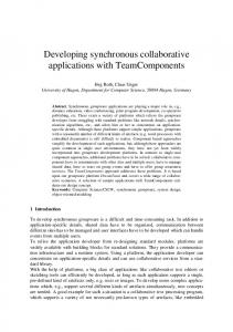
Artefact Management System), an artefact-based Process Support System [13][14] that provides functionalities to manage human resources, projects, and artefacts. ADAMS has a web-based architecture and includes several subsystems. The Artefact Management Subsystem is the core subsystem of ADAMS and provides functionalities to manage the artefacts of a project and concurrent development of software engineers. This subsystem is used to create, modify, and delete artefacts, as well as to manage the artefact state and versions. Traceability links between related artefacts can also be inserted, visualised, and used for impact analysis during software evolution. Artefacts in ADAMS can either be atomic entities (associated to one or more files) or they can be composed of an arbitrary number of sub-artefacts. In other words, ADAMS enables fine-grained management of software artefacts that can be hierarchically organised, thus providing a product-oriented work breakdown structure to the project manager [7]. Software engineers are notified when other concurrent developers make some changes to the artefacts they are allocated to. Software engineers can also subscribe events occurring to artefacts they would like to be notified about. Finally, the traceability layer can be used to propagate events concerning changes made to an artefact to the dependent artefacts. STEVE has been integrated in ADAMS to provide synchronous and asynchronous collaborative modelling functionalities. In particular, it allows developers to access and modify the same UML diagram at the same time, thus allowing distributed team members to discuss and model the system directly within ADAMS. In this way, the different versions of each model element, as well as the textual information shared during the meeting are maintained in ADAMS. To this aim, the Artefact Management Subsystem is used to access the artefacts of a given project, to version diagrams and elements, and to store dependencies between elements and diagrams. Finally, STEVE exploits the event and notification management functionality of ADAMS to notify events concerning an edited diagram to the involved developers. STEVE has been designed to take advantage of the fine-grained artefact management provided by ADAMS. In fact, STEVE enables software engineers to concurrently develop UML diagrams by managing versions of diagram elements and relations and allowing them to be shared across different UML diagrams, system models, and documents in a consistent way. From this point of view, the tool also promotes the reuse of artefacts. 4. Synchronous Collaborative Development in STEVE The physical architecture of STEVE (see Figure 1) is based on a communication infrastructure that aims at improving the context awareness among software engineers in a distributed development setting. In particular, software engineers are enabled to concurrently modify the same diagram at the same time based on the MVC pattern. The user interface (view) is developed as an applet running within a
5
web page of the ADAMS user interface and uses a Coordination Server (controller) to keep all the views of the diagram (model) updated.
Figure 1. STEVE Architecture
When a user accesses a specific UML diagram (e.g., one of the two diagrams listed in Figure 2) from the ADAMS user interface, the web page connects to the STEVE server to download the current version of the diagram and the applet to edit it. In case this is the first user accessing the diagram, the STEVE server (i) checksout the last version of the diagram from ADAMS, (ii) sends the diagram and the identifier of the user to the Coordination Server, and (iii) returns the identifiers of the diagram to be used in the communication between the STEVE applet and the Coordination Server. The applet then establishes a socket connection with the Coordination Server to get the current version of the diagram. When another user tries to concurrently access the same diagram, the STEVE server simply sends the identifier of the user to the Coordination Server and returns the identifier of the diagram to make the ADAMS client able to communicate with the Coordination Server. Figure 2 shows an example of list of UML diagrams that a particular software engineer has the permission to access within a project for the development of an eshop. New diagrams can also be created, depending on the permissions of the software engineer. In particular, the diagrams listed in Figure 2 are two use case diagrams, namely UCD Product Purchase and UCD Stock Reorder. Figure 3 shows the STEVE applet where the use case diagram UCD Product Purchase has been selected and a new use case is being inserted in the diagram. Existing use cases and actors present in other diagrams and/or documents can also be reused and inserted in the diagram, thanks to the fine-grained artefact management provided by ADAMS. The Coordination Server is responsible for keeping all the views of the diagram consistent and managing the coordination among the software engineers working on the same diagram at the same time. This coordination is achieved by using a token: each time a software engineer has to apply a change to the diagram, he/she takes the token thus preventing other developers to make changes to the diagram. The communication among the software engineers is also guaranteed by the possibility to exchange textual messages within a collaborative session.
6
Figure 2. List of available UML diagrams
Figure 3. Adding a new use case
When the user holding the token commits the changes to the diagram (by performing a check-in operation), the diagram description is sent back from the Coordination Server to STEVE that uses the versioning functionalities of ADAMS to create a new version of the diagram and of the modified elements. New and deleted elements are also managed by STEVE, accordingly. In particular, in case a new element is created and inserted in the diagram, STEVE creates a new artefact in ADAMS and links it to the diagram. In case the element inserted in the diagram is reused from the ADAMS repository, the artefact is simply linked to the diagram by adding a new traceability link and a new version is created in case it has also been modified. Elements removed from the diagram are not removed from the repository, as they can still be used in other diagrams.
7
5. Enhancing STEVE with fine-grained artefact management STEVE relies on ADAMS fine-grained versioning management for history management and concurrent editing of both the diagram and each of the included components. Hence, composite artefacts and components are managed as different configuration items. Figure 4 shows the meta-model supporting the fine-grained versioning of a use case diagram. It is important to note that each element of a diagram can be related to a description (e.g., the description of a use case can contain its pre and post conditions, the flow of events, and exceptional conditions). As a consequence, the diagram and each of its elements can have files associated, whose versioning is provided by the Revision Control Subsystem of ADAMS. The file of the composite artefact is used to store the corresponding diagram representation, while the descriptions of each diagram element are stored in different files. Such a separation is also valuable for the reuse of components across different diagrams. Fine-grained artefact management also enables the software engineer to specify traceability links between entities within the same document, as well as between parts of two different documents or diagrams, resulting in a more precise impact analysis. Moreover, a fine-grained artefact management reduces the likelihood of conflicts arising when different software engineers apply changes to the same element. In fact, in case the document is decomposed in sub-artefacts, a conflict occurs only if changes concern the same sub-artefact. It is worth noting that, even if such kind of conflict (i.e., changes occurring in different parts of a document) can be usually addressed by automatic merge algorithms for textual documents, the scenario is much more complicated when dealing with non-textual documents. Moreover, since a diagram is decomposed in a hierarchy of simpler objects eventually annotated with text, the definition of more precise access policies to diagram parts is also enabled, thus allowing a finer task allocation and responsibility identification. This is particularly important in a distributed environment, where a work breakdown structure is usually defined to decompose the project components into manageable tasks assigned to distributed development teams. STEVE adopts the check-out/check-in paradigm adopted in most of the current versioning and Configuration Management (CM) tools [2][11][31]. In particular, a pessimistic approach to manage concurrency is adopted. This approach prevents conflicts due to modifications applied by different software engineers to the same diagram. To ensure a pessimistic access control to the diagram as well as each of the contained elements, locks have to be recursively propagated across the hierarchy. When a UML diagram is checked-out, both the diagram and the contained elements are locked. This means that in case UML diagrams sharing elements are checked-out at the same time, the shared elements can only be edited in the first checked-out diagram, while they are locked in the other diagrams. As a
8
consequence, developers working on other diagrams can modify all diagrams elements except the shared elements previously locked in other diagrams. For example, suppose that a software engineer, namely Bob, checks-out the use case diagram UCD Stock Reorder in Figure 2 to add a new use case, namely Verify Order Status (see Figure 5). Suppose that another software engineer, namely Alice, would insert the same use case in the use case diagram UCD Product Purchase, while Bob is still working on the use case diagram UCD Stock Reorder. As shown in Figure 6, the Verify Order Status use case is locked in the use case diagram UCD Stock Reorder (its colour is grey) and Alice can only include it without making any change.
Figure 4. Entity objects of STEVE use case model
Figure 5. UCD Stock Reorder use case diagram
9
Figure 6. Locked use case
It is worth noting that diagram elements can also be shared with analysis and design documents. The lock applied to the UML diagram ensures that shared elements cannot be concurrently modified within the documents (and vice-versa). For example, a different perspective of the fine-grained artefact hierarchy of a UML diagram is shown in Figure 7a. This figure shows how software artefacts composing the use case diagram UCD Product Purchase have been locked when Alice checked-out the diagram. Consequently, the elements are also locked in each diagram including them (see Verify Order Status within UCD Stock Reorder in Figure 7a). Figure 7b shows the structure of the requirements analysis document after the check-out of the use case Product Purchase. Also the sections containing the descriptions of the locked use cases are marked with the lock symbol. This prevents from concurrently modifying the description of the use cases from different perspectives. It is worth noting that the reuse can produce unexpected side effects. In fact, in case a diagram element is shared across different diagrams, changes (e.g., renaming or changing the description) of a shared element affect all the diagrams containing it. The software engineers working on affected diagrams could be interested in any applied change. As an example, in case Alice modifies the use case Verify Order Status in the UCD Product Purchase, the UCD Stock Reorder will be marked as out-of-sync, as it contains the changes element. The system visualises this situation by means of an exclamation mark close to the artefact name in the hierarchical view (see Figure 7b). Notifications of such events are also sent via e-mail by using the event and notification functionality of ADAMS.
10
(a)
(b)
Figure 7. Hierarchical views of the model elements (a) and RAD (b) artefacts.
6. Conclusion Software development in geographically distributed environments presents software engineering challenges, as the interaction among team members requires the management of consistency and concurrency among project artefacts. To face up these challenges, Computer Supported Collaborative Work research has focused on supporting collaboration in many applications including concurrent visual modelling. However, most of the available cooperative modelling environments provide poor versioning functionalities. Even when versioning is provided, these tools lack in integration with the global development process. In this paper we have proposed STEVE, a synchronous collaborative visual modelling tool that supports distributed UML modelling of software systems. The tool provides a communication infrastructure that enables the concurrent editing of the same diagram at the same time. Complex UML diagrams are decomposed and managed in a fine-grained hierarchy of sub-artefacts, thus providing change and configuration management functionalities for both the diagrams and graphical objects. Thus, software predefined diagram components can be consistently reused across the different diagrams of a given project. STEVE is integrated in ADAMS, an artefact-based Process Support System that provides fine-grained artefact management functionalities and enables sharing of diagrams and diagram elements with high level documentation, thus enhancing reuse and consistency within the project. The ADAMS system has been experimented during the last two academic years within the software engineering courses at the University of Salerno. In particular, ADAMS has been used to coordinate the work of project teams composed of one or
11
two master students with management roles and from six up to eight undergraduate students with development roles [7]. We also plan to experiment STEVE, during the analysis and design phases of future projects. Dedication The authors would like to dedicate the results of the research work described in this paper to prof. Stefano Levialdi. In particular, prof. Genny Tortora has collaborated in the past with prof. Levialdi on different topics in the field of visual languages. These researches have then evolved in several directions and stimulated further researches, including the work described in this paper. References [1] [2] [3] [4]
[5]
[6]
[7]
[8] [9]
[10]
[11] [12]
[13]
ArgoUML website, http://argouml.tigris.org B. Berliner, “CVS II: Parallelizing software development”, Proceedings of 1990 Winter USENIX Conference, Washington, D.C., USA, 1990, pp. 341-352 Borland Togheter website, http://www.borland.com/together/ N. Boulila, “Group Support for Distributed Collaborative Concurrent Software Modeling”, Proceedings of the 19th IEEE International Conference on Automated Software Engineering, Linz, Austria, 2004, pp. 422-425. N. Boulila, B. Bruegge, and A.H. Dutoit, “Computer Supported Cooperative Software Engineering: A framework for supporting distributed concurrent group modeling of software”, Proceedings of the International Conference on Applied Computing, Lisbon, Portugal, 2004, pp. 11-15. N. Boulila, B. Bruegge, and A.H. Dutoit, “D-Meeting: an Object-Oriented Framework for Supporting DistributedModelling of Software”, International Workshop on Global Software Development, International Conference on Software Engineering, Portland, Oregon, 2003, pp. 34-38. B. Bruegge, A. De Lucia, F. Fasano, G. Tortora, “Supporting Distributed Software Development with fine-grained Artefact Management”, Proceedings of International Conference on Global Software Engineering, Florianopolis, Brazil, 2006, pp. 213-222. D. Chen, C. Sun, “Consistency maintenance in real-time collaborative graphics editing systems”, ACM Transactions on Computer-Human Interaction, vol. 9, nr. 1, 2002, p.1-41. Q. Chen, J. G. Hosking, J. C. Grundy; “An e-whiteboard application to support early design-stage sketching of UML diagrams”, Proceeding of IEEE Symposium on Human Centric Computing Languages and Environments, IEEE Computer Society, Auckland, New Zealand, 2003, pp. 219-226. M. Chu-Carroll, J. Wright, and D. Shields, “Supporting aggregation in fine grained software configuration management”, Proceedings of the 10th ACM SIGSOFT Symposium on Foundations of Software Engineering, Charleston, South Carolina, USA, 2002, pp. 99-108. B. Collins-Sussman, B.W. Fitzpatrick, and C.M. Pilato, “Version Control with Subversion”, O’Reilly (ed.), 2004. C.H. Damm, K.M. Hansen, M. Thomsen, “Tool Support for Object-Oriented Cooperative Design: Gesture Based Modeling on an Electronic Whiteboard”. In Turner, T., Szwillus, G., Czerwinski, M., Paterno, F. (eds.), Proceedings of Conference on Human Factors in Computing Systems, ACM Press, The Hague, The Netherlands, 2000, pp. 518-525 A. De Lucia, F. Fasano, R. Francese, and G. Tortora, “ADAMS: an Artefact-based Process Support System”, Proceedings of 16th International Conference on Software Engineering and Knowledge Engineering, Banff, Alberta, Canada, 2004, pp. 31-36.
12
[14] A. De Lucia, F. Fasano, R. Oliveto, and G. Tortora, "ADAMS: ADvanced Artefact Management System", Proceedings of 10th European Conference on Software Maintenance and Reengineering, Bari, Italy, 2006, pp. 347-348. [15] P. Dewan and J. Riedl, “Toward Computer-Supported Concurrent Software Engineering”, IEEE Computer, vol. 26, nr. 1, 1993, pp. 17-27. [16] N. Graham, H. Stewart, A. Ryman, R. Kopaee, and R. Rasouli, “A World-Wide-Web Architecture for Collaborative Software Design”, Proceedings of Software Technology and Engineering Practice, Pittsburgh, Pennsylvania, 1999, pages 22–32. [17] J. Grudin, “Computer-Supported Cooperative Work: History and Focus”, IEEE Computer, vol. 27, nr. 5, 1994, pp. 19-26. [18] J.C. Grundy, W.B.Mugridge, J.G. Hosking, and R.W.Amor, “Support for Collaborative, Integrated Software Development”, Proceedings of the 7th Conference on Software Engineering Environments, IEEE CS Press, The Netherlands, 1995, pp. 84-94. [19] J.C Grundy, J.R. Venable, J.G. Hosking, and W.B. Mugridge, “Supporting Collaborative Work in Integrated Information Systems Engineering Environments”, Proceedings of the 7th Workshop on the Next Generation of CASE Tools, Greece, 1996. [20] A. Haake and J.M. Haake. “Take CoVer: Exploiting Version Support in Cooperative Systems”. Proceedings of Conference on Human Factors in Computing Systems, Amsterdam, The Netherlands, 1993, pp. 406-413. [21] Hurwitz Report, Collaborative UML Development, White Paper, CanyonBlue Incorporated, 2001. URL http://www.canyonblue.com/whitepapers.htm. [22] iServer UML website, http://www.orbussoftware.com/uml.aspx [23] M. Lozano, “Consistency Maintenance Framework For Collaborative Software Modeling Tools”, Technical Report TCD-CS-2003-58, Trinity College, University of Dublin, 2003. [24] MagicDraw UML, No MagicInc., URL:http://www.magicdraw.com [25] B. Magnusson and U. Asklund, “Fine grained version control of configurations in COOP/Orm”, Proceedings of the 6th International Workshop on Software Configuration Management, New York, NY, 1996, pp. 31-48. [26] Microsoft Visio web site, http://office.microsoft.com/visio [27] T. N. Nguyen, E. V. Munson, J. T. Boyland, and C. Thao, "Infrastructures for Development of ObjectOriented Configuration Management Services", in Proceedings of the 27th ACM/IEEE International Conference on Software Engineering, St. Louis, Missouri, USA, 2005, pp. 215-224. [28] H. Oliviera, L. Murta, and C. Werner, “Odyssey-VCS: A Flexible Version Control System for UML Model Elements”, Proceedings of the 12th International Workshop on Software Configuration Management, Lisbon, Portugal, 2005, pp. 1-16. [29] Poseidon for UML, Gentleware AG, website, http://www.gentleware.com/ [30] Rumbaugh, J., Jacobson, I. and Booch, G. The Unified Modeling Language Reference Manual, Addison Wesley, 1999. [31] C. Sun, X. Jia, Y. Zhang, Y. Yang:`` REDUCE: a prototypical cooperative editing system,'' Proceedings of the 7th International Conference on Human-Computer Interaction, San Francisco, USA, 1997, pp.8992. [32] W.F. Tichy, “RCS: A System for Version Control”, Software Practice & Experience, vol. 15 no. 7, 1985, pp. 637-654.
13