to use a near infrared (NIR) flash image, instead of a normal visible flash image ... flash/no-flash images and generate a noise-free and detail en- ... The hot mir-.
Proceedings of 2010 IEEE 17th International Conference on Image Processing
September 26-29, 2010, Hong Kong
ENHANCING LOW LIGHT IMAGES USING NEAR INFRARED FLASH IMAGES Shaojie Zhuo1
Xiaopeng Zhang1
Xiaoping Miao2
1
Terence Sim1
2
School of Computing Computer Science National University of Sigapore
School of Computing Computer Science Sun Yat-Sen University
ABSTRACT In low light environment, photographs taken with a high ISO setting suffer from significant noise. In this paper, we propose to use a near infrared (NIR) flash image, instead of a normal visible flash image, to enhance its corresponding noisy visible image. We build a hybrid camera system to take an visible image and its NIR counterpart simultaneously. We introduce a new method to denoise an visible image and enhance its details using its corresponding NIR flash image. Experimental results show the superiority of our method compared with previous image denoising and detail enhancement methods. Index Terms— Computational photography, near infrared photography, image denoising, detail enhancement 1. INTRODUCTION It is challenging to take photographs under low light conditions. To avoid motion and defocus blur, a high ISO setting is required to reduce the exposure time, which leads to high noise in captured photographs. Image denoising techniques have been applied to enhance noisy images. Some common image denoising methods include field of experts [1], patch matching methods [2], and edge preserving filtering [3, 4, 5]. These methods work well when noise level is low. However, as the noise level increases, they tend to blur edges and details of the image. An alternative is to use a flash. A flash adds artificial light to the scene, so that we can obtain a sharp, noise-free image. However, as the color temperature and intensity of flash light are usually different from those of the ambient light, the use of flash may ruin ambiance atmosphere and introduces unwanted artifacts, such as red eye, undesired reflections, harsh shadows and specularities. To remove the artifacts caused by flash, variety approaches have also been proposed. Some early work focus on flash image red-eye correction [6] or white balancing [7, 8, 9]. Recently, the flash/no-flash methods [10, 11] use joint bilateral filter to combine a pair of flash/no-flash images and generate a noise-free and detail enhanced image. However, these methods require successive capture of at least two images of the same scene, which restricts their applicability to static scenes. Moreover, in many
978-1-4244-7993-1/10/$26.00 ©2010 IEEE
2537
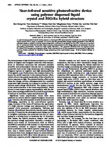
Visible image V
NIR image N
BM3D denoising [2]
Our method
Fig. 1. Our method uses a pair of V/N images and generates a high quality noise-free image with fine details. It outperforms single image denoising methods such as BM3D. types of low light photography, such as night time animal photography, or photography in some churches or museums, a visible flash is no allowed. In these situations, previous approaches using ambient/flash image pairs can not be applied. In this paper, we propose the use of a near infrared (NIR) flash, coupled with our hybrid camera system which can take a visible image (V ) and its corresponding NIR flash image (N ) simultaneously. The NIR flash emits only NIR light when fired. NIR light is outside the range of visible light. Thus, it can lighten the scene without dazzling the objects being photographed. Moreover, the capture of visible and NIR flash images can be performed simultaneously, relaxing the restriction on static scenes. We then present a new method to enhance a noisy visible image using its corresponding NIR flash image taken under low light conditions. Our method is able to reduce the noise of the visible image significantly and enhance its detail, while keeping the atmosphere of original scene. Figure 1 shows an example of our result. Infrared photography has been invented for many years and commonly appreciated for its artistic value. Recently, it has also been exploited in computational photography. Zhang et al. [12] enhance the contrast and details of a visible
ICIP 2010
Input
Intensity
Input
V
Vb
Base
S
VI
Intensity
N
D
Noisereduced
Color
VC b
Detail- V de enhanced I
VI b
VI nr
Detail
Output
V de
Nd
S (a) Our hybrid camera system
(b) Workflow of our method
Fig. 2. Our hybrid camera system and workflow fo our method. In (b), S and D denote normal and dual WLS smoothing respectively. | · | denotes pixel-wise multiplication. image using its corresponding NIR image, but their work can not work under low light conditions. The closest work to ours is the dark flash photography [13], which makes use of both NIR and near ultraviolet (NUV) light for low light image enhancement. Our work differs from theirs in several ways: 1) Our method use only a NIR flash image to enhance a visible image instead of both NIR and NUV images they used and is able achieve comparable results; 2) Our method adopts the denoising and detail transfer framework and is much faster than theirs; 3) Our hybrid camera can take a V/N pair simultaneously while their prototype camera required two shots to take such a pair.
free NIR image N . The NIR images are RGB color images with false colors due to white balance setting and NIR spectral properties of the sensor. As NIR light is near to red light in light spectrum, we use the red channel of the captured image to represent the NIR image. 3. VISIBLE IMAGE ENHANCEMENT Given a V /N image pair, we use the NIR flash image N to denoise the visible ambient image V and then apply detail transfer to futher enhance the detail of the denoised result. The workflow of our method is illustrated in Fig. 2(b). 3.1. Denoising
2. IMAGE ACQUISITION NIR light has the wavelength ranging from 750nm to 1400nm. Most CCD/CMOS based digital cameras can sense it quite well. However, digital camera manufactures usually add a IR cutoff filter over the sensor to avoid unwanted artifacts caused by NIR light. As shown in Fig. 2(a), we build our hybrid camera system using two SONY F828 cameras. The hot mirror reflects NIR light and lets only visible light pass through. Camera V takes visible images. We remove the IR cutoff filter of camera N to make it be able to capture NIR light. The two cameras are connected with a single controller, so that they can capture a V /N image pair by a single click on the controller. We carefully setup the two cameras to ensure they are optically aligned. We also make the focal length and aperture of the two camera same to guarantee geometric alignment of each image pair. When taking images in low light conditions, we use a high setting (ISO 1600) for the visible camera and a low ISO setting (ISO 80) for the NIR camera. We mount a NIR flash to camera N and fire it when taking an image pair. The NIR flash is built by mounting a NIR filter to a normal flash. The NIR filter, whose transmission starts at 730nm, blocks the visible light and lets only NIR light out. In this way, we can take a sharp noisy image V and a sharp, noise-
2538
Our visible ambient image denoising builds on weighted least squares (WLS) smoothing [14]. Given an image V , the WLS smoothing seeks a new image V b , which is as close as possible to V , and is also as smooth as possible everywhere except at significant gradient locations in V . Formally, V b can be expressed as V b = arg min Vb
� � �
Vpb − Vp
�2
� + λ ax,p
p
�
∂V b ∂x
�
�2 + ay,p p
∂V b ∂y
(1)
where the subscript p denotes the pixel location and λ balances between the two terms. For normal WLS smoothing, the spatially varying smoothness weights ax,p and ay,p are defined as follows: abx,p
� �−1 ∂ log(V ) α = +� , ∂x p
aby,p
� �−1 ∂ log(V ) α = +� , ∂y
(2)
p
where � is a small constant (typically 0.0001) to avoid division by zero. α controls the sensitivity to gradients of V . Typically, its value ranges between 1.2 and 2.0.
�2 �� , p
We apply the normal WLS smoothing to V in each RGB color channel. The value of λ depends on the noise level of the image V . For a higher noise level, λ is set larger. Using normal WLS smoothing, we can remove the noise in visible image V to some extend. However, as the noise level varies in different regions of the image, some regions may be oversmoothened. The NIR flash image N contains the same image structure with the visible image and it is not contaminated by noise. Thus, we can use it to guide the smoothing to avoid over/under-smoothing. However, as different materials have different reflectivity to visible and NIR light, some edges in V may disappear in N , which leads to edge blur in smoothing results. However, those edges, especially the strong edges, can be found in V b . Hence, we use the information from both V b and N to perform the smoothing. The image N is monochromic and contains no color information. Therefore, we convert image V from RGB color space to YIQ color space and denote its intensity (Y channel) and color components (I and Q channels) as VI and VC . Similarly, we denote the intensity and color components of image V b as VIb and VCb . We extend the normal WLS smooting and apply it on VI . The new smoothing has the same form with Equ. 1. We combine the gradients of VIb and N , then define the new smoothness weights as, � �−1 ∂ log(N ) ∂log(VIb ) α +� · , ∂x ∂x � �−1 ∂ log(N ) ∂log(VIb ) α +� · = , ∂y ∂y
anr x,p = anr y,p
(3)
where | · | denotes scalar multiplication. Because the smoothing uses the information from both V and N , we call it dual WLS smoothing. The output of dual WLS smoothing is the noise reduced intensity component of the visible image, denoted by VInr . 3.2. Detail transfer Although the dual WLS smoothing reduces the noise while preserving edges of the visible image, some image details are still lost. We observe that the NIR flash images are usually sharp and contains details of the scene. We can extract the detail of image N and transfer it to the noise-reduced image VInr . To transfer detail, we apply normal WLS smoothing on the NIR flash image N and obtain its base layer N b . Then the detail layer N d is represented using the quotient image of N and N b , i.e., N , (4) Nd = b N +� where the constant � (typically 0.0001) is to avoid division by zero. Now the detail-enhanced intensity VIde of the visible image can be expressed as: VIde = VInr · N d ,
(5)
2539
(a)
(b)
(c)
(d)
Fig. 3. The teapot example. (a) The V /N image pair, (b) Detail transfer without mask, (c) Shadow and specularity mask, (d) Detail transfer with mask. where | · | denotes pixel-wise multiplication. VIde is then combined with the color component VCb and converted back to RGB color space. Finally, we obtain the detail-enhanced visible image V de . 3.3. Shadows and specularities detection NIR flash may introduce shadows and specularities in images, which affect the results of both the denoising and detail transfer. We detect those regions using the same methods used in [11]. Shadows are detected by finding the regions where |N − VI | is small and specularities are found by looking for saturated pixels in N . After we get the shadow and specularities mask M , we blur it using a Gaussian filter to feather the boundaries. The final output is the alpha blending between V de and V b , based on the mask M , i.e., V f inal = (1 − M ) · V de + M · V b .
(6)
Figure 3 illustrates how shadow and specularity mask correct artifacts in direct detail transfer. 4. EXPERIMENTS To demonstrate the strength of our approach, we test our method using variety of examples. As shown in Fig. 1, we compare our method with BM3D [2], a state of the art image denoising method. Both methods is able to remove noise present in the visible image, but BM3D blurs the edges, while our method preserves and enhances details of the image. We compare our method with joint bilateral filtering (JBF) [11] in Figure 4. Both methods use NIR flash images achieve noise reduction and detail enhancement. However, JBF suffers from several problems. Firstly, due to lack of color information in the NIR image, JBF causes color shift in the result (indicated by the red rectangle). Two different colors may have similar intensities in the NIR flash image, which makes JBF average between two different colors and leads to color shift. Secondly, as some edges in visible images disappear in NIR flash images, JBF has severe edge blur problem (indicated by the green rectangle). Besides, JBF may introduce halo artifacts along strong edges (indicated by the blue rectangle). With the increase of noise level, JBF need to increase both spatial and range support to remove the
Visible image V
NIR image N
JBF result
Our result
Fig. 4. Comparison of our method with joint bilateral filtering (JBF). Our method can avoid color shift, edge blur and halo problems that JBF suffers from. ing. We also like to use NIR flash images for image deblurring. Although few exploited, we believe that NIR light has great potential in computational photography. 6. REFERENCES [1] S. Roth and M. J. Black, “Fields of experts: A framework for learning image priors,” in CVPR, 2005. [2] K. Dabov, A. Foi, V. Katkovnik, and K. O. Egiazarian, “Image denoising by sparse 3-D transform-domain collaborative filtering,” IEEE Trans. Image Processing, 2007. [3] P. Perona and J. Malik, “Scale-space and edge detection using anisotropic diffusion,” PAMI, 1990. [4] A. Buades and J. M. Morel, “A non-local algorithm for image Inputs Dark flash result Our result denoising,” in CVPR, 2005. [5] Carlo Tomasi and Roberto Manduchi, “Bilateral filtering for Fig. 5. Comparison of our method with dark flash method. gray and color images,” in ICCV, 1998. The input images are taken from [13]. [6] Matthew Gaubatz and Robert Ulichney, “Automatic red-eye detection and correction,” in ICIP, 2002. noise, leading to over-blur of edges and halo artifacts when [7] M. Ebner, “Color constancy using local color shifts,” in ECCV, applying detail transfer. In contrast, our dual WLS smoothing 2004. uses information from both NIR image N and visible base [8] Eugene Hsu, Tom Mertens, Sylvain Paris, Shai Avidan, and image V b . it is able to produce high quality results. Fr´edo Durand, “Light mixture estimation for spatially varying We also compare our method with the dark flash method [13]. white balance,” in SIGGRAPH, 2008. They used both NUV and NIR for visible image enhance[9] Min H. Kim and Jan Kautz, “Consistent scene illumination ment. As shown in Fig. 5, our method is able to produce using a chromatic flash,” in Proc. Computational Aesthetics in comparable results. Moreover, our method is much faster. Graphics, Visualization, and Imaging, 2009. Comparing to their method spending 30 minutes on process[10] Elmar Eisemann and Fr´edo Durand, “Flash photography ening a 1.3M-pixel image, ours only takes about 4 minutes. hancement via intrinsic relighting,” SIGGRAPH, 2004. [11] Georg Petschnigg, Richard Szeliski, Maneesh Agrawala, Michael Cohen, Hugues Hoppe, and Kentaro Toyama, “Digi5. CONCLUSION tal photography with flash and no-flash image pairs,” in SIGGRAPH, 2004. In this paper, we present a method of enhancing a low light noisy image using its NIR counterpart. We build a hybrid [12] Xiaopeng Zhang, Terence Sim, and Xiaoping Miao, “Enhanccamera system which is able to take a V /N image pair by a ing photographs with near infra-red images,” in CVPR, 2008. single shot. Using the normal and dual WLS smoothing, we [13] Dilip Krishnan and Rob Fergus, “Dark flash photography,” in can reduce the noise and enhance details of a noisy visible SIGGRAPH, 2009. image. Compared with previous image denoising and detail [14] Zeev Farbman, Raanan Fattal, Dani Lischinski, and Richard enhancement methods, our method is able to produce results Szeliski, “Edge-preserving decompositions for multi-scale with higher visual quality and using less processing time. In tone and detail manipulation,” in SIGGRAPH, 2008.
the future, we are going to apply our method on video denois-
2540