Enhancing Product Development Through Parametric and Product Data ..... hoc system of naming and storage which is only known by a few individuals within.
Enhancing Product Development Through Parametric and Product Data Management Tools Eric N. Wiebe Graphic Communications Program John Summey Furniture Manufacturing and Management Center North Carolina State University Abstract Expanding on work previously conducted with the Furniture Manufacturing and Management Center, the current project continues the evaluation of how parametric-based 3-D CAD and product data management (PDM) software tools can be utilized better in the furniture industry. The central focus of this work is the development of a demonstration system which uses a parametrically driven 3-D CAD/PDM system as the core tool for creating and managing a product database. This demonstration system was used to develop a methodology demonstrating how once a piece of furniture was modeled in the system, and how future iterations based on this base piece could easily be developed for manufacture. The demonstration was based on a production upholstered sofa frame.
Wiebe, E. N. & Summey, J. (1997). Enhancing product development through parametric and product data management tools. FMMC (TR 97- 1).
2
1.0 Current Project Goals Past work for the Furniture Manufacturing and Management Center (Assessment Of Current Trends In Computer-Aided Design And Manufacturing In The Furniture Industry, TR# 95-03) revealed that CAD is a presence in a majority of furniture companies in the region, but its full potential has not been reached. The technical report to the FMMC (TR# 95-03) suggested that two of the primary routes to accessing its potential was the use of 3D modeling tools and better integration of CAD through product data management (PDM) systems into product planning, development, and manufacturing. The next logical step was to provide a more detailed demonstration as to how enterprisewide systems could be configured to take advantage of the product model being created in the 3-D CAD system. This paper describes an in-depth investigation of one particular segment of the furniture industry: the upholstered furniture products area. Of particular interest was the product development process of the wooden frames used in the upholstered furniture. The project encompassed a number of activities, including: - Exploration of current 3-D CAD and PDM systems, especially those in the midrange portion of the market. - A close investigation of the product development process in this segment of the industry. - Development of a methodology as to how upholstered frame designs might be developed and managed in a CAD/PDM system 2.0 New Product Development Technologies 2.1 Constraint-based 3-D Solids Modeling Tools As with many industries, CAD usage in the furniture industry is concentrated in product engineering and in the factory for programming CNC machinery. In many companies, the use of CAD within product engineering is limited to its use as a drafting tool. Yet, CAD — and constraint-based 3-D solids modeling in particular — has the potential of much more than simply automating the drafting process. At the core of 3-D solids modeling is the creation of a computer-based model of the proposed furniture piece. In addition to modeling individual parts of a furniture piece, more sophisticated modelers have the capability to manage complete assemblies of all of the parts of the furniture piece. For both individual parts and assemblies, models created with constraint-based tools can enhance the development process by automating the modification process based on the design intent. These capabilities mean that 3-D modeling systems have the capability of contributing to troubleshooting the design of individual pieces as well as the overall assembly. The transition from the use of CAD as a drafting tool for producing parts sketches for route sheets to a tool for creating virtual models of complete furniture pieces means a rethinking of how CAD is integrated into product engineering. At the level of the single part, 3-D CAD allows for the modeling of parts as they actually are rather than as a 2-D 'sketch' of the part. Often, because a 2-D drafting system is
Wiebe, E. N. & Summey, J. (1997). Enhancing product development through parametric and product data management tools. FMMC (TR 97- 1).
3
only creating a symbolic representation of a part, liberties are taken with the drawing which distort its true proportions and leaves out details in the interest of saving time. Since the 2-D sketch is used almost exclusively as support documentation for part fabrication processes listed on the route sheet, the information contained in the drawing only needs to adequately represent those operations. This is true even if a 2-D CAD system is used to create the drawing. If a 3-D computer model of a part is going to be used in an analysis of the completed furniture piece, then it must accurately represent its size, proportions, and details (to an appropriate level) in relation to the other parts in the assembly. There can be considerable pay-off from being able to create a 3-D computer model of furniture pieces before production, however, there is the need for more up-front time to create accurate models of individual parts. Time needed to create computer models can be shortened considerably if models can be re-used rather than created from scratch. In most types of furniture pieces, the majority of parts are made using common production processes and joinery methods. For that reason, the parts share similar topologies (shapes) and differ primarily in their size and proportions. For example, in a casegoods piece, a majority of rails may be rectangular with tenons at either end and differ primarily in their overall width and length. Constraint-based (parametric or variational) modeling tools associated with most advanced solids modeling systems are designed to exploit the derivative nature of many manufactured pieces. By defining features (such as a tenon) as a series of programmable dimensions, the process of modifying an existing model can be semiautomated. Again, time must be taken to apply these parameters to a model, but if the part is going to be reused in dozens (or hundreds) of designs, then considerable cost savings can be realized. Successful use of constraint-based modeling is dependent on developing consistent strategies as to how parameters are going to be named, created, and related to other parameters. At the most general level, parametric definition needs to define the design intent of the part/assembly being modeled; that is, parameters are defined based on how the model would be modified. In order to do this, careful analysis and documentation of the design process is needed in order to implement constraintbased techniques. Currently, most product development groups have a majority of their design intent stored in the heads of their staff rather than formally embodied in their CAD models. The design intent can only be revealed in these organizations indirectly by looking at iterations of a design as they are drawn by hand or in 2-D CAD. Changes made in individual parts or in assemblies are based on deep knowledge of the manufacturing processes used to make the part, structural and assembly requirements of the piece, and aesthetic goals for the design. The challenge is: how can this critical, implicit knowledge be made explicit through parametric, programmable dimensions of a 3-D computer model? The advantages could be many, including: 1) letting the computer lessen the quantity non-quality enhancing detail work of documenting a design, 2) speeding the training of new employees, 3) and unifying the process of product development within a company.
Wiebe, E. N. & Summey, J. (1997). Enhancing product development through parametric and product data management tools. FMMC (TR 97- 1).
4
2.2 Product Data Management Tools A significant challenge in product engineering is the coordination and management of all the information pertaining to furniture parts, pieces, and suites. Whether a company employs manual drafting, 2-D CAD drafting, or 3-D solids modeling, this management problem exists and can consume considerable staff time doing 'nonquality enhancing' activities. In deciding how to manage this information, the process begins by examining the engineering information generation, modification, and distribution process. In addition, the type of drafting/CAD system used to generate engineering documentation will dictate to some degree the type of strategies you employ to manage this information. With an all drafting-based system, the information may not only reside in the drawing themselves, but in auxiliary documentation generated on spreadsheets, word processors, hand filled out forms, etc. Companies using a 2-D CAD system often don't function much differently than they did when they were producing drawings using manual drafting. Where a 2-D CAD system is used strictly for automated drafting, the drawings are often plotted and distributed through the organization much the same way manually produced drawings are. Much in the same way, other types of documentation such as bill-out sheets can be produced in computer-based spreadsheet software, printed out, and distributed much as the manually produced documentation was. Whether they were originally produced by hand or by computer, computer-based document management tools offer a way in which traditionally produced documents can be organized. Product database tools can be used to track the distribution of current documents and manage information such as what is the current revision number, who has signed off on the design, and who was the originator of the document. For legacy documents, if the document exists in paper form only, the database may indicate what cabinet drawer the drawing is filed in. With a 2-D CAD system, the names of the computer files themselves contain important identifying information used to organize information. Obviously, on-line storage can be much more efficient in terms of physical space, however, it brings with it additional responsibilities to safeguard the digital information from accidental erasure. In such a scenario, the database tools used to track the paper or electronic documents might best be referred to as product document management systems. As outlined in FMMC technical report TR# 93-03, 3-D CAD can be integrated at many different levels into a furniture company. One approach would be use the 3-D CAD system as a method for generating more traditional 2-D documentation. Even if this approach were taken, the 2-D documentation is an end product rather than a beginning point of the product development process. If the 3-D model is treated as the central generating point of product information, then the goal is to leverage the information implicitly contained within the model and link it to the model product information created externally of the 3-D CAD system. The change in focus is to think of 3-D CAD as a generator of product information rather than simply a document producer. The database tools, in turn, are used to coordinate product information both within, and external to, the CAD system. In such a scenario, the database tools might best be described as a product data management system since they do more than coordinate paper documentation.
Wiebe, E. N. & Summey, J. (1997). Enhancing product development through parametric and product data management tools. FMMC (TR 97- 1).
5
2.3 Coordination of product information The close melding of the 3-D CAD system and the product data management (PDM) system means that decisions of purchasing and strategies for implementation of these two critical tools should not be done separately. Depending on the 3-D CAD system, the PDM component may be very tightly integrated within it (meaning that the PDM component is probably a 'module' of the 3-D CAD system). This tight integration may also mean that the CAD system is capable of creating and modifying a majority of the product information needed for production. On the other hand, the 3-D CAD system may be more modest in capabilities and depend on a third party PDM system for data/document management and other external programs for creation of some portion of the product database. For example, it may be that there is still a separate bill-out process where product information derived from the 3-D model is placed in a spreadsheet. In this case, an important role of the PDM system will be to coordinate the appropriate 3-D model parts and spreadsheet files; when the 3-D model is modified, the proper spreadsheet is presented to be modified appropriately. The two scenarios of CAD/PDM integration presented above also raises another issue: the level of automation in product information generation. When the CAD and PDM systems are tightly integrated, there are probably 'hooks' allowing access to raw model data and used to generate useful product information through a high level programming language. When the 3-D CAD system has more modest capabilities, generation of product information implicit within the CAD model and the coordination of this information is likely to be left to auxiliary software systems. The ability to automate the generation of information normally contained on the bill-out sheets in an external spreadsheet program will be dependent, in part, on the robustness of the CAD software's API (application program interface) and open systems standards such as ActiveX™ (developed by Microsoft). The level of integration between the various software tools used to generate and manage product information will depend on a number of factors: - The willingness to spend capital for a more powerful, sophisticated CAD system which has a PDM system built in and/or a robust API. - The willingness to spend time and money to program, up-front, those routines that will automate the generation of product information. - The degree to which the company's product development process is standardized enough that the product information generation can be automated without creating too many 'exceptions' which have to be either specially coded or hand entered. - The degree to which the preconfigured system (either by the software vendor or a consulting firm) meets the goals and needs of the company's production development process. 2.4 Interaction of CAD/PDM and Organizational Issues The size and complexity of the product database managed by a PDM system will also be determined by how much of the organizational structure within the furniture company it plans to encompass. For example, the amount and types of product information managed by the PDM system will differ depending on whether bill-out, routing, process, and costing information is included in the database. The relationship of the PDM system to the organization needs to be carefully analyzed.
Wiebe, E. N. & Summey, J. (1997). Enhancing product development through parametric and product data management tools. FMMC (TR 97- 1).
6
A more all-encompassing PDM system which manages information for all divisions involved in design and production may have the potential for better coordination, but may also lead to an unwieldy database which is not optimized for any one function in the organization. Issues such as the level of technical expertise of the staff, the level of expected support from the Information Systems (IS) group in the company, and the existing corporate culture concerning training and on-the-job learning will all play a role in the choice of systems. Where staff do not expect much support for learning and managing a new, and sophisticated system they may choose to implement a fairly modest evolution of their current system. On the other hand, in an environment where there is support for implementing a new system — even when in the short run their may be a drop in productivity in the division — a more far-reaching change in technology and workflow can be considered. Whether the changes are modest or large scale, the end goal is meeting long range company goals of improving productivity and gaining agility in meeting changing market demands. 3.0 Applications within the Upholstered Furniture Industry 3.1 Product Development Process Site visits to upholstered furniture operations during 1995 and 1996 pointed up product data management issues which were both unique to their operations but also showed applicability to other areas of the furniture industry, for example. Like other areas of the furniture industry, the upholstered furniture industry has a wood-based component. Like casegoods, upholstered furniture operations use a number of fairly standardized components in the production of frames for upholstered seating. Unlike casegoods operations, many factories inventory parts for future assembly rather than cutting to order for production runs. These companies then, not only have the production issues to concern themselves with, but also inventory of both rough and finished stock. Upholstered furniture frames are largely hidden from view in the final furniture piece. For that reason, the shaping, cutting, and joining of parts tends to be rougher and less accurate than it would need to be in a typical casegoods piece. The primary goal of the frame is to act as a skeletal system for the furniture piece: providing structural support and a basic dimensional shape on which springs, foam, other cushioning, and fabric can be placed to give it its final form. For this reason, virtually all of the parts of a frame consist of simple geometries with straightforward joining methods (often doweling and screws). Goals in designing the frame often center around minimizing both the quantity of wood within a part and the total number of parts without compromising the structural integrity of the piece. The level of accuracy of cutting is controlled by achieving structurally sound joints and minimizing wood waste. Another driving force is providing adequate nailing and support surfaces for the attachment of the suspension system (springing), cushioning, and fabric. In many ways, the design of the frame is derived through a top-down process: first, the final form and look of the upholstered piece is determined by the designer, second, a suspension system and cushioning method is specified, and finally a frame is designed to accommodate
Wiebe, E. N. & Summey, J. (1997). Enhancing product development through parametric and product data management tools. FMMC (TR 97- 1).
7
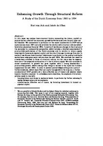
these first two specifications. For example, the height of the seating rail on the frame will be determined by the final seating height minus the cushioning and suspension system height plus the inset of the suspension system within the frame. Derivation of the frame components from the designers sketch differentiates the furniture industry from many others where the geometry of standardized parts plays a large role in determining shapes and sizes. The implications of this differ depending on the area of furniture. In casegoods, where parts are cut to order, no parts are inventoried. On the other hand, in a upholstery operation where parts are inventoried, the management of these parts can lead to considerable expense where every new furniture piece generates numerous new parts to be warehoused and tracked. Besides the amount of money tied up both in warehouse space and actual inventory, there is also concern when the management of these parts involves an ad hoc system of naming and storage which is only known by a few individuals within the company. 3.2 Development of a Demonstration 3-D Modeling System Within the upholstered furniture industry, there considerable potential for the use of both 3-D solids modeling and product data management tools in the design and production of frames for upholstered seating. First, the simple geometries of the frame pieces can be modeled on a wide range of solid modeling systems. Second, the dimensional changes in frames usually take place in rather predictable ways such that a particular method of joinery using a set number of parts could be used to describe the frames of a large number of seating pieces. The implication for these two facts is that upholstered seating frames are well suited for exploiting the efficiencies of a variational or parametric-based solids modeling system where multiple designs can be easily derived from a single 'generic' 3-D frame model. Finally, if the virtual part models being created in product engineering could be coordinated with the actual pieces being held in inventory, then there is the potential for optimizing the number of different parts being stocked. The goal of a 3-D modeling system should not only to assist the product engineer in generating the parts for a new design, but also to match the parts of a new design to parts already in inventory in the hopes that existing parts can be used rather than creating new ones. One of the initial challenges, then, is to find a way of geometrically defining the parts of an upholstered frame in such a way as to respect the production processes used to fabricate the parts and to allow designers and engineers to describe and modify the parts in ways that are used to working. Working from both the parts drawings and the actual parts of upholstered frames, a system was developed to describe the frame parts. The starting point for the system was to understand the generic design of a sofa frame. Figure 1 represents the generic design of a sofa. Besides the three primary overall dimensions, both the Depth and Height dimensions are broken down into secondary dimensions representing key sub-regions of the primary dimension. The dimensions can be described as follows:
Wiebe, E. N. & Summey, J. (1997). Enhancing product development through parametric and product data management tools. FMMC (TR 97- 1).
8
- D: The orthogonal depth dimension defined as the inside edge of the back post to the inside edge of the front post. The inside edge of the back post is reference point H. This dimension will typically define the internal rails supporting the spring frames and indirectly defines seating depth. The actual side rail lengths can be derived as a trigonometric function of angle AB and D. - DA: The distance from the inside edge of the back post (reference H) to the inside edge of the stump. This dimension indirectly defines arm depth. In designs where the stump is coincident with the front leg, DA = D. As with dimension D, in designs where there is splay (angle AB > 0), the actual arm length will be a trigonometric function of AB. - H: The orthogonal height dimension is defined as the distance from the floor (reference A) to the top of the back post (reference E). It is recognized that reference E will not always be the highest point on the frame, since the back may curve up in the center. In this case, the overall height of the couch can be derived from reference E and the curvature of the top back rail (dimension H plus the derived distance). - HA: The distance from the center of the dowel/screw hole attaching the arm to the stump to the top edge of the seating frame rails (reference C). This distance indirectly defines the arm-to-seat height. - HB: The distance from the top edge of the seating frame rail (reference C) to the bottom edge of the seating frame rail (reference B). This dimension defines the seating box depth. It is recognized that the seating box may be constructed of either one or two rails. - HC: The distance from the bottom edge of the seating frame (reference B) to the floor (reference A). This distance indirectly defines the clearance of the seating box from the floor. - W: The orthogonal width dimension is defined as the distance from the inside edges of the two back posts. This distance defines the length of the back seating box rail. If the design has splay (angle AB > 0), the front rail length can be derived as a trigonometric function of AB. - AB: The splay angle in the width/depth plane. This angle will be used to help define the cutting angles and lengths on the side and arm rails. - AA: The seating angle of the back post in the height/depth plane. This angle, along with reference D, will be used to help define the length of the arm relative to reference H. This angle indirectly defines the back angle relative to the seat.
9
Wiebe, E. N. & Summey, J. (1997). Enhancing product development through parametric and product data management tools. FMMC (TR 97- 1).
G G
W
AB F F
E E
D DA AA D D
HA
H
C C
HB B B
HC A A H H
Figure 1. The primary and secondary dimensions are defined relative to key reference points on the frame.
Wiebe, E. N. & Summey, J. (1997). Enhancing product development through parametric and product data management tools. FMMC (TR 97- 1).
10
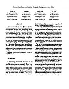
These dimensions, rather than defining individual parts directly are used as global variables from which individual parts can be defined. Individual parts of a sofa frame are defined by two types of dimensions: perimeter dimensions and machining dimensions. A perimeter dimension defines the gross dimensions of the part which are largely based on the previously defined global dimensions. These dimensions are the primary means of defining the shape and form of the part. A machining dimension defines the size and location of a secondary machining operation used to fasten frame parts together. Size machining dimensions are derived from the fastener used (e.g., dowels, screws) and are not typically based on global dimensions. Location machining dimensions are based on the perimeter dimensions of the individual parts. Because in many cases the perimeter dimensions are based on global dimensions, location machining dimensions are also based on these global dimensions. Some of the naming conventions used for part dimensions are as follows: - Sizes, when used as component of the name of a dimension, are given in decimal equivalents rounded to the nearest hundred and multiplied by 100. So for example 1/2" (50/100 x 100) would be represented by 50 and 1 1/8" (112.5/100 x 100) by 112. - Generic machining operations which create a simple shape that can be defined by a discrete set of dimensions are named according to the operation. For example, a boring operation is defined by the size of the hole (e.g., BR_DIA50), its depth (e.g., BR_DP75) and the offset distance in two dimensions from a common reference point (e.g., BR_OF125) or from another bore (e.g., BR_SP150). Where possible, the location machining dimensions are located relative to key surfaces of the part. Key part surfaces, such as the end face of a rail, are likely to be easily located relative to the previously defined global reference points. - Perimeter dimensions specific to individual parts are named based on the part number and its relation to the primary dimensions of length, width, and thickness. For example, the overall length of part #207 would be labeled L207. If there are dimensions which reference features which have not otherwise been labeled, they are labeled in sequence as a sub-series (e.g., L207_1, L207_2, etc.). As with the machining dimensions, these dimensions are referenced from previously defined reference points and/or from key surfaces on the part. - Where possible, perimeter dimensions should be derived from global dimensions (e.g., L476 = D). Where a number of parts share a common derived dimension that is not related to a global dimension, a secondary global dimension can be defined to relate those parts together. - Where machining operations are located based on the geometry of a part rather than a fixed dimension, global or perimeter part dimensions should be used to specify the machining location. A common example would be the location of a bore at the center of the thickness of a part regardless of the actual thickness. This location would be notated as: T477_1 = T477 / 2. - Perimeter dimensions within a part can also be defined in relation to each other (e.g., W653 = L653 * .05). Figure 2 shows an example of a sofa frame part parametrically defined using the above system. Sample parts from a complete sofa frame constructed and constrained in Autodesk Designer™ can be seen in Appendix A.
11
BORE_OF87
W476
BORE_OF87
BORE_OF150
BORE_OF375
T476_1
T476
Figure 2. Dimension constraint definition of a side rail.
L476 = D / cosAB L476_1 = DA + BORE_OF62 T476_1 = T476 / 2
BORE_DIA50
BORE_DIA25
L476
L476_1
AB
Wiebe, E. N. & Summey, J. (1997). Enhancing product development through parametric and product data management tools. FMMC (TR 97- 1).
Wiebe, E. N. & Summey, J. (1997). Enhancing product development through parametric and product data management tools. FMMC (TR 97- 1).
12
The primary driving force behind a logical naming system for parameterized dimensions is the understanding that this information is used as more than a private naming system by the CAD operator. Establishing CAD model/drawing standards is always a goal within a company, but 3-D constraint-based CAD makes this especially important. With traditional 2-D CAD drawings, the geometry of a part was explicitly represented in the CAD file. When a CAD operator opened the file — whether they were the original creator or not — the geometry they wanted to modify or query was directly represented in the database. Modifications to the drawing could be made by directly modifying isolated geometric values of the part. With constraint-based models, the situation is different. The viewed geometry is derived from the constraint-based rules contained in the database which may be related to numerous features in a part and/or parts in an assembly. When a CAD operator wants to modify the geometry of a part, they need to know what constraint rules were established in order to correctly predict how modifications will affect the complete part/assembly. As previously mentioned, if the strategy for constraining the sofa frame match the design intent, and all the CAD operators accessing the model share a common knowledge of the design intent, then they can modify the constrained model with an understanding of how it is going to behave. Many frames will have unique features which do not match the generic constraint model, but if the operator can spend his time on integrating the unique elements into the generic model rather than confirming the structure of the generic components, then time will be saved. The generic structure also provides a set of primary global constraints and a mechanism for creating secondary constraints to ease the integration of frame-specific parts and design details. Even for frames with unique elements, the majority of parts will already be in place and constrained according to the generic model, saving considerable time when the frame is adjusted to the overall proportions based on the primary global parameters. Another reason for standardizing the constraint model is that this information can be linked to external databases accessed by many people in the engineering and manufacturing operations. Much of the information in product databases in manufacturing is either directly or indirectly derived from the geometry of parts. For example, route sheets will carry specific dimensional information for different machining operations. Costing calculations will be dependent, in part, on the number of board feet being used for a part. In order to fully maximize the gain in agility from using a product database, all aspects of the database which are sensitive to a particular geometry of a part should be 'aware' of when that geometry is modified. That is, it should automatically update the derived information when the base geometry of the part is changed. A company may or may not have immediate plans on implementing a sophisticated PDM system with this sort of capability, but by implementing a standardized method for constraining geometry in a model, they will ease the transition when such a system is implemented. This standardization can have paybacks at all levels of automation. If you ease the ability to access or publish base geometry information, you make it easier for members of the design team to make use of this information.
Wiebe, E. N. & Summey, J. (1997). Enhancing product development through parametric and product data management tools. FMMC (TR 97- 1).
13
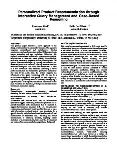
In upholstered frame design, there are three possible applications for linked geometric constraint information within product engineering: 1.) By the designer to establish the proper proportions for an upholstered piece. 2.) By the product engineer/designer team to query a parts inventory for existing parts which share similar dimensions and shapes. 3.) By the product engineer to derive cutting specifications for the route sheet. The first usage can be achieved by direct manipulation of the parameters which define the 3-D computer model and is an inherent feature of all parametric/variational modelers. Similarly, the third usage is typically available through a third party add-on package or programming within a macro programming language within the modeler. More difficult is the second usage. Here, the modeling system must be linked with a product data management (PDM) system which brings together information of the part currently being defined with parts currently in inventory. A carefully developed logical structure of defining parameters will be critical to matching parts in the database. 3.3 Development of a Demonstration Product Data Management (PDM) System In addition to building the generic upholstered sofa frame in Autodesk Designer, key information about the frame parts were also put in a PDM package sold by Autodesk, WorkCenter™. WorkCenter could be considered a entry-to-mid-level PDM package designed to run on a Novell™ server and linked to Windows™-based (3.1, 95, and NT) clients. From a single client workstation, a user can create/modify a 3-D model of a frame in Designer and query/enter parts into the WorkCenter database. Since WorkCenter only allows 2-D AutoCAD drawings to be linked to it, the 3-D model parts need to be stored separately on the client or server. WorkCenter defines a new entry in the database for each revision of a part. This means that parts can be retrieved based on either their most current revision or a previous revision. The database also categorizes revisions based on which ones have been approved. The messaging functions within WorkCenter also allows sending and receiving messages relating to the work on the frame with other staff using WorkCenter. The basic configuration of the CAD/PDM system configuration used in this project is outlined in Figure 3. In setting up the PDM system, one of the first things to do is to determine exactly what information is going to be contained within the database. With WorkCenter, as the database is set up, the exact fields (categories of information) which are going to be used have to be defined. WorkCenter has a set of predefined fields and a finite (about a dozen) custom fields which can be defined. Each field is named and assigned a data type (e.g., integer, text string). Though the name of a field can be changed after the database is set up, the data type of a field and the number of custom fields cannot. In addition, distinctions are made as to whether a field is global to all revisions of a part or specific to a particular revision. For example, the name of a part would be global to all revisions, while the date revised would be specific to a revision. The process of defining the fields must be done up front and be done with great thought, since it would be very costly to decide a year and thousands of parts later that you really need to have another field added to each of the parts. In order to do a thorough job at field definition, a company needs to have
14
Wiebe, E. N. & Summey, J. (1997). Enhancing product development through parametric and product data management tools. FMMC (TR 97- 1).
Client Workstation Designer
AutoCAD
WorkCenter
Server WorkCenter AutoCAD drawings
Designer models
Client Workstation Designer
AutoCAD
WorkCenter
Client Workstation Designer
AutoCAD
WorkCenter
Client Workstation Designer
AutoCAD
WorkCenter
Figure 3. Data/Network organization of Autodesk's AutoCAD, Designer, and WorkCenter.
Wiebe, E. N. & Summey, J. (1997). Enhancing product development through parametric and product data management tools. FMMC (TR 97- 1).
15
a clear understanding of how they want their product development process established, what information will be needed by all of the parties in the process, and how much of this information will be contained within the PDM database. In the demonstration system, a key concern to be addressed is assisting product development staff in leveraging existing inventory of upholstered frame parts. Both the definition of 3-D model constraints and the linkage of this information to the PDM system will allow for querying the PDM system for parts which match the dimensions and joinery requirements of frames currently being designed. Ideally, this will mean the ability to reuse existing part designs rather than defining new ones, thus using up existing inventory of parts rather than doing more cuttings for a new part definition. The hope is that easy querying and retrieval of existing parts through the PDM system will allow engineers to quickly mock up 3-D CAD models for approval by the designer. If existing parts can be found in inventory which are within a reasonable size variation of the one initially proposed by the designer, then the existing part can be used instead of creating a new one. Even if the designer insists on proportions which demand new parts, existing part models with similar machining operations can be located and easily modified to fit the new frame model. All of this will only be possible if a standardized methodology is used for defining the constraints of the parts. If nomenclature and constraint strategy of the legacy part models is haphazard, then the operator will find it quicker to build new part models from scratch rather than be able to reuse existing ones. Within WorkCenter, predefined and custom-defined fields are placed on a 'card template'. As a part is retrieved from the database, these cards then define the spatial layout and color coding of the fields on the screen (see Figure 4). Since each revision of a part is stored separately, every document has one card for globally defined fields of a part and another card for revision-specific fields. In the demonstration PDM system, the following fields were used: Global Fields (on the 'Document Information' card) - Suite name - A one word text field. This was an existing field which was renamed. - Piece name - A one word text field. This was an existing field which was renamed. - Part number - A numeric value. - Originator - Person who entered the part into the database. This is equivalent to the 'login name' of the user on the system. - Note - A multi-word text field where the name of the part and/or other descriptive information can be added. - Document type - What program (e.g., AutoCAD, Excel, etc.) created the attached document. - Date added - The date the initial revision of the part was added to the database. - Date last changed - The date the latest revision was added to the database.
Wiebe, E. N. & Summey, J. (1997). Enhancing product development through parametric and product data management tools. FMMC (TR 97- 1).
16
Revision specific Fields (on the 'Revision Information' card) - Revision number - An alphanumeric code consisting of a letter followed by a number. The letter indicated the major (i.e., approved) revision level while the number indicates the incremental revision level within the major revision. The number is incremented every time a drawing is checked out. - Date last changed - Same as the field on the above card - Length - A custom numeric field indicating the value of length constraint of the part. - Width - A custom numeric field indicating the value of width constraint of the part. - Thickness - A custom numeric field indicating the value of thickness constraint of the part. - Number of end bores - A custom numeric field indicating the number of bores in the end faces of the part. For example, for joining rails to posts or stumps. - Number of face bores - A custom numeric field indicating the number of bores put in faces perpendicular to the grain. For example, for joining posts or stumps to rails or braces.
Figure 4. GUI for WorkCenter. The 'cards' are at the bottom of the screen.
Wiebe, E. N. & Summey, J. (1997). Enhancing product development through parametric and product data management tools. FMMC (TR 97- 1).
17
The combination of standard fields, renamed standard fields, and custom fields gives the operator the ability to search the database for parts which are both part of ongoing and legacy designs. Though the demonstration system did not include this, there is the potential of linking inventory information to this database. Examples of the types of queries which can be done with the database as it is currently defined, include: - How many parts in a current suite need to be ripped to a particular width? - What rails in the database are between 24" and 24.5" in length and 1" thick? - What rails are over 36" in length, at least 3" wide, part of a discontinued suite, and could be cut down and reused? - What parts were created by the new trainee CAD operator so they can be brought up and checked. - Who was the last operator to modify this part? The inability of WorkCenter to directly attach 3-D model files to database entries means that 2-D AutoCAD drawings generated from the 3-D models (a relatively automated process) were used in their place. This may not be much of an imposition if 2-D drawings are going to continue to play a role in a companies documentation process. For example, if 2-D part drawings are going to be attached to route sheets, then these drawings represent the document which manufacturing is going to use to refer to during the cutting process. Since the 3-D model base source information from which the drawings are generated, care must be taken to carefully coordinate the 3-D model files outside the database with the 2-D drawing files directly linked to the database (see Figure 3). Another area where data has to be coordinated by the operator is the geometric information about the part entered into the custom fields. There is no direct linkage between the data in the Length, Width, Thickness, No. of End Bores, and No. of Face Bores fields and the values of their geometric counterparts in the 3-D model. The coordination is assisted, though, by some of the interface linkages provided between WorkCenter and AutoCAD. In the demonstration system, the AutoCAD drawings were generated from the Designer model such that the key geometric dimensions were automatically displayed in the multiview. In addition, the custom fields for the WorkCenter document could be entered while in AutoCAD and while you could directly review the dimension values. In addition, the custom WorkCenter fields were defined as linked text blocks on the AutoCAD drawings, so that these field values would also be plotted on the drawing. 4.0 Summary The demonstration system described in this report showed how the current generation of CAD/PDM tools could be applied to the furniture industry. The chosen tools, Autodesk's AutoCAD, Designer, and WorkCenter, represent the entry to mid-level range of the constraint-based 3-D modeling and PDM market. Because Autodesk products are currently being used by such a large number of furniture companies, it also represents a system configuration which is likely to be considered by many of them. The described system shows how such a system can be used to implement a fundamental rethinking of how product data is created and managed in a furniture company. It also points up that not all processes will be 'automated'
Wiebe, E. N. & Summey, J. (1997). Enhancing product development through parametric and product data management tools. FMMC (TR 97- 1).
18
with such a system. Such a system provides operator assistance in both the creation and management of furniture design, especially engineering data. By freeing the operator from repetitive and non-quality enhancing activities, the operator can then put efforts towards more cognitively demanding tasks of defining the best possible design for a furniture piece as quickly as possible and with the fewest number of errors. An important element in implementing a CAD/PDM system, such as the one described in this report, is establishing a larger context in which such a system is both specified and implemented. As advanced as the new software/hardware technology might be or as sophisticated as the constraint definition methodology, if the system does not reflect how a company wants to evolve its design and product engineering divisions, then the system will be a failure. Current work underway at the FMMC is looking at developing survey, interview, and observation techniques which can be used as part of an organizational assessment of the product engineering division of a furniture company. This assessment includes delineating both the current and proposed product development process, the skill level of the employees, the management structure, and possible impacts new technology might have on the functioning of the division. Out of this assessment, a plan can be proposed how to best implement a CAD/PDM system in any furniture company. This assessment and implementation plan is critical to assure that tools and processes are developed which directly support the desired product development process and which can and will be implemented by the employees of the division.
Wiebe, E. N. & Summey, J. (1997). Enhancing product development through parametric and product data management tools. FMMC (TR 97- 1).
Appendix A Sample Constrained Sofa Frame Parts
19