allows to rigorously check the traffic within the CAN system, including the value and time .... 3) Traffic shaping: In busâbased CAN, a node may monop- olize the ...
Enhancing Security in CAN Systems using a Star Coupling Router Roland Kammerer and Bernhard Fr¨omel and Armin Wasicek Institute for Computer Engineering Vienna University of Technology, Austria E–mail: {kammerer,froemel,armin}@vmars.tuwien.ac.at
Abstract—Controller Area Network (CAN) is the most widely used protocol in the automotive domain. Bus-based CAN does not provide any security mechanisms to counter manipulations like eavesdropping, fabrication of messages, or denial–of–service attacks. The vulnerabilities in bus–based CAN are alarming, because safety–critical subsystems (e.g., the power train) often deploy a CAN bus, and hence a failure propagation from the security domain to the safety domain can take place. In this paper we propose a star coupling router and a trust model for this router to overcome some of the security deficiencies present in bus–based CAN systems. The CAN router establishes a partitioning of a CAN bus into separate CAN segments and allows to rigorously check the traffic within the CAN system, including the value and time domains. We evaluate the introduced trust model on a prototype implementation of the CAN router by performing attacks that would be successful on classic bus–based CAN, but are detected and contained on router–based CAN. The router can consequently increase the security in automotive applications and render some of the attacks described in the literature (e.g., fuzzying attack) on a car useless. Since the CAN router offers ports that are compatible to standard CAN, the router can be used to increase the security of legacy CAN based systems.
I. I NTRODUCTION Currently, the CAN protocol [12] is the most widespread field bus protocol in the automotive industry. It is valued mainly for its robustness, simplicity, low cost and its decentral structure. A modern car contains up to 70 Electronic Control Units (ECUs) [1] which are connected to various CAN buses and realize automotive subsystems like power train, fuel– delivery, or electrical control. These applications are increasingly driven by software. Software offers application designers a tremendous flexibility to design, implement, and maintain their products. However, these benefits bring also drawbacks. Software offers no inherent mechanisms to protect itself from unauthorized modifications and is therefore prone to manipulation. In automotive environments, manipulations become manifest for example in chip tuning (modification of the parameterization of an ECU), or power box attacks1 (insertion of fake ECUs). In particular, the CAN protocol offers no mechanisms to counteract manipulations of a bus line. Devices can be arbitrarily added or removed by simple branch lines. Due to its broadcast nature an attacker, or a malicious component, can eavesdrop all the communication on the bus. Even worse, a 1 http://www.mehrleistung.com/
single component can disrupt the communication of all other CAN nodes by constantly sending high priority messages. In safety–critical applications such malicious interaction faults are even more dangerous, because they can trigger a failure propagation from the security to the safety domain. We introduce a CAN router that aims to improve the dependability aspects (which are discussed in [17]) as well as the security properties of a CAN system as our main contribution of this paper. The router is implemented as a dedicated device that is able to • partition a CAN bus into several independent segments • regulate and control the traffic between these segments • facilitate integrity, plausibility, and consistency checks on messages The paper is organized as follows: In Section II we provide an overview about the related work in the field of CAN. In Section III, we elaborate on a trust model for CAN systems. We propose the design of a CAN router to resolve some of the security deficicies of CAN in Section IV. Then, we evaluate our hypotheses in Section V, discuss the results in Section VI and finally, we draw a conclusion in Section VII. II. R ELATED W ORK Due to CAN’s use in many application domains, there has been a lot of work (academic as well as industrial) to overcome the existing limitations of bus-based CAN. Proposed solutions range from simple bus guardians [4], [11], to replicated CAN buses [22], [23] and reconfigurable transmission media [7]. While these solutions improve the dependability of CAN, they suffer from the bus-based nature of CAN. For example bus guardians protect the bus from a faulty or malicious node, but they do not provide countermeasures if the bus itself fails. Solutions that favor replicated buses do not provide fault isolation in case messages (e.g., from a babbling idiot) are sent on replicated buses. Even solutions sharing design decisions with our approach (i.e., implementing a star topology) have severe limitations. By basically implementing an AND function these solutions still forward potentially malicious messages to all connected nodes. Disadvantages of existing active and passive star implementation are discussed in [3]. More sophisticated active star implementations like CANcentrate [3] come with additional costs and do not tackle security sufficiently. CANcentrate uses separated up- and downlinks to discriminate the input signals from individual nodes from the computed result
of the logical AND function. While providing improvements regarding fault detection and isolation, none of the mentioned solutions focuses on security. A main advantage of the CAN router is its clean decoupling of distinct CAN segments. The router avoids the global AND function by implementing a store and forward behavior. Unlike any of the previously mentioned solutions, our CAN router also utilizes a priori knowledge about permitted behavior in the time domain. We consider this additional knowledge as a prerequisite to detect attacks in the time domain (e.g., flooding). To our best knowledge none of the existing gateway/hub approaches considers time as an important parameter in order to increase the security properties of CAN based systems. III. T RUST M ODEL Trust is a relationship between actors in a given environment. A trustor is the subject that trusts an entity (i.e., consumer/producer of information) and a trustee is the entity that is trusted (i.e., the information being consumed) [8]. For example, a bank customer (trustor) trusts his bank (trustee) that the money is securely managed. An actor’s decision to enter into a trust relationship implies necessarily the acceptance of some perceived risk. This acceptance of risk can be motivated by providing some sufficient credible evidence leading the trustor to believe that the trustee is trustworthy. For instance, there is a (low) risk that a bank goes bankrupt. An actor has to accept this risk before depositing the money into the bank. The bank deploys security mechanisms like guards and strongboxes to assure its trustworthiness. A trust model provides the capability to effectively model and deduct such trust relationships. It encompasses information about actors, entities, and their trust relations, essentially, who trusts whom by relying on which evidence. In a computer system, a Trusted Computing Base (TCB) is a small amount of software and hardware that security depends on and that we distinguish from a much larger amount that can misbehave without affecting security [14]. The services of the TCB should guarantee that the damage that any misbehaving component outside the TCB (e.g., a compromised device driver) can do, is limited according to the privileges that were granted to the component in the first place. Hence, the TCB acts as a trustee for its users (trustors). The trustworthiness of a TCB is enforced by dedicated security mechanisms. The remainder of this section presents a trust model for a bus–based CAN system. We work on the implicit trust relationships present in a CAN system and analyze their justification by contrasting the trust relationships to practical attacks on CAN systems described in literature. Next, we introduce a CAN router which can help to mitigate certain effects of attacks and contribute to a CAN system’s TCB. This section finishes with an extended trust model for a CAN system using a star topology and our CAN router. A. A Trust Model for Bus–based CAN A bus-based CAN system assumes that the entire hardware and software concerned with the transmission and reception of
CAN messages is part of the TCB. Therefore, an application acts as trustor and the interfaced CAN subsystem as trustee. In particular the application has to make the following assumptions: • A message is not eavesdropped, modified, or removed during transmission on a CAN line or until accessed by the application in the controller. • Each message has an authentic sender, meaning that each message can be assigned to an existing, original sender and no fake messages have been introduced. In practice, these assumptions are unrealistic and the trust relationship between application and CAN subsystem does not hold. Several papers [9], [13], [10], [5] investigate attacks on CAN and deliver proof–of–concept implementations of attacks on CAN buses in an automotive environment. Boiling down the insights gained in these papers, it turns out that most attacks assume two prerequisite manipulations to the structure of a CAN system before launching attacks on a particular part of the application: • Inject malicious code in an original ECU to gain control over the node (e.g., a chip tuning attack). • Attach a malicious device to the CAN bus to add a new controller, to replace an existing one (e.g., power boxes), or to insert malicious logic to the physical bus. Consequently, a corrupt node can be used to launch the following attacks in a bus–based CAN system: • Fabrication: A fake message can be inserted into the system. A corrupt node can (i) fabricate a new message with a CAN identifier that is not yet present in the system or (ii) use an existing identifier to fake messages sent by an existing node. In the former case not all connected nodes will store the fabricated message in their receive buffers, because the controller filters incoming messages according to their message identifier. A special case of fabrication is a fuzzying attack, which sends valid messages with a random payload at a very high rate in order to disturb the receiving application. • Modification: In this scenario an attacker physically cuts the connection between a node and the CAN bus in order to intercept message transmissions from that node (also known as man-in-the-middle attack). For the attacker it is then possible to read the messages of the isolated node, change the contents of the messages and transmits those altered messages to the CAN bus. • Denial–of–Service: If a corrupt node arbitrarily upsets bits, the transmitted frame will be destroyed. By repeatedly destroying frames on the bus, a node’s service can be severely affected. A simple Denial of Service (DoS) attack in a bus–based CAN setup is to assert and hold a dominant state on the bus. In a more sophisticated DoS attack the malicious node constantly sends messages at a very high priority, thus suppressing all other messages on the bus. • Eavesdropping: Because of the broadcast nature of the CAN bus, each node receives all messages on the bus.
•
The filter in the receive unit of the CAN controller decides which messages are accepted. However, a corrupt node can be programmed to receive all messages. Removal: Messages can be removed from the bus, for example, by directly cutting off a node from the bus. This way, all messages that will be emitted by the node are suppressed. Another possibility to remove messages is to insert a terminator resistor which consumes a message’s energy from the CAN line.
CAN ROUTER (MPSOC) Segment with Multiple Nodes CAN Node CAN Node
The key to the success of the above described attacks is the manipulation of the CAN system’s TCB. Given the fact that there are no countermeasures to protect the TCB in a standard, bus–based CAN system, the prerequisite manipulation is fairly easy to achieve. In this paper, we propose to replace the bus–based communication system with a dedicated CAN router. This CAN router enables the arrangement of network segments in a star topology and facilitates the dependable exchange of messages between these segments. The CAN router enforces the trust relationship between application and CAN subsystem through rigorous checking of messages. Moreover, it can be used to implement architectural services which constrain and control the CAN traffic flowing through the router. Besides having a profound effect on the dependability of the CAN system [17], we can observe certain security properties that sustain the ideal trust model given in the beginning of this chapter. Therefore, we argue that the proposed CAN router effectively establishes a TCB in a CAN system. C. New Trust Model for CAN Systems using a Router Installing a CAN router in a CAN system implements new trust relationships in the system. One constraint of this solution is that we can only give these guarantees for messages that are transmitted between two CAN segments connected to the router. Whatever happens within a segment is not in the sphere of control of the CAN router. Following relations between any two segments hold: 1) Unidirectional channels: A CAN message crosses the router in a unidirectional fashion. The configuration of the router specifies which segments are connected and the data direction of the connection. Therefore, a message can be related to a specific sending segment (if the destination segment is free of malicious manipulations). 2) Traffic partitioning: The destination segments of a CAN message on the star are configurable. Consequently, not all connected segments receive all information that is distributed through the communication system. This enforces the confidentiality between different CAN segments through isolation. 3) Traffic shaping: In bus–based CAN, a node may monopolize the communication system. A central entity like the CAN router can be used to regulate the message rate between segments and to reduce the message collision
TTNoC
Mgmt. Port to Ethernet Network
CIS
CAN port to CAN bus
CIS
CIS
CIS
CIS
CAN Node Segment with a Single Node CAN Node
CAN Node CAN Node CAN Node
IP Cores:
CIS CAN Interface Subsystem CAN Node
B. Improving the CAN Communication Infrastructure
CIS
MU
TTNoC
MU Management Unit
Time-Triggered Network-on-a-Chip
Fig. 1: CAN router
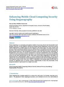
rate in a CAN system. This improves the availability of connected segments. 4) Message integrity: The integrity of a communication system is enforced if deviations from the norm can be detected. For instance, this can be done by performing regular checks on operations and data. These checks introduce end–to–end integrity properties between CAN segments according to the particular nature of a check. 5) Intrusion detection: As the central element which can access all messages in the system, the CAN router is predestined to implement a network–based intrusion detection system. Intrusion detection was identified as a key element to improve the security of CAN [9]. The above described trust relationships improve the security properties of CAN messages in a subtle way. An important aspect is that none of these relationships requires the introduction of expensive 2 cryptographic ciphers. Hence, by replacing the bus–based communication system with a star coupling router, we achieve to give security guarantees between CAN segments connected to the router. IV. CAN ROUTER Figure 1 depicts a CAN system using the CAN router. CAN segments, consisting of at least one CAN node, are connected to the router via a CAN port. The router itself is realized as a Multi-Processor-System-on-a-Chip (MPSoC), where every CAN port is served by its own CAN Interface Subsystem (CIS). Every CIS consists of a CAN controller [21], a Nios II softcore CPU, local memory and a routing configuration. The routing configuration allows a source CIS to forward a received CAN message to one or more destination CISes via a Time-Triggered Network-on-a-Chip (TTNoC) [16]. Additionally, the router possesses a management port that is served by the Management Unit (MU). The paper [24] analyzes the inherent security properties of system designs based on a TTNoC. These properties serve as a foundation to establish the CAN router’s TCB. 2 While computation time and memory consumption might not be an issue nowadays, the additional communication overhead for key management and modification of legacy/third party CAN nodes is assumed to contribute considerably to costs.
In the following we describe the basic services of the CAN router, explain their implementation, and state their importance
CAN Transceiver
CAN Interface Subsystem 1
CAN Transceiver
CAN Interface Subsystem N
CAN Controller SJA 1000
CAN Out CAN In
Nios II Filtering Logic Routing Configuration Priority Queue
On-Chip Interconnect: Time-Triggered Network-on-a-Chip
CAN Out Port 0 CAN Out Port 1 CAN Out Port N CAN In Port 0 CAN In Port 1
TTNoC
Management Subsystem CAN Interface Subsystem 0
NoC Interface
Listing 1: A simplified routing entry typedef struct { time64 min, max; time64 last_arrived_min, last_arrived_max; uint16_t message_check; uint16_t forward_to; } routing_entry;
Eth. Transceiver CAN Transceiver
CAN Controller Interface
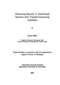
A. Implementation and Basic Services The design decision for a MPSoC was motivated by decoupling temporal behavior of every CIS by a TTNoC and by an increased scalability: Our design provides better scalability compared to single core solutions where processing power has to be shared among all CISes. Even a single additional message can influence the timing in a way that the system as a whole would stop being operational. Multi-processor systems can suffer from the same effect if the software executed is not properly parallelized (i.e., it is executed on only one core). We avoid these limitations by providing a separated, encapsulated processing subsystem with local memory per CIS. Figure 2 shows the internal structure of a single CIS. Receiving a CAN message from a source CAN segment is represented by a message flow from the left to the right. The source CIS receives the message from the CAN controller, processes it according to the routing configuration and forwards the message to the TTNoC. On the receiver side a CIS processes the messages it received from the TTNoC and sends the messages to the destination CAN segment. In Figure 2 this is depicted as a message flow from the right to the left. Internally, the router’s message processing is strictly timetriggered and divided into rounds of activity, where these rounds are triggered faster than the minimum interarrival time of CAN messages at 1 Mbit/s. We use the generic timer service of the underlying Time-Triggered System-on-a-Chip (TTSoC) architecture [19] to synchronously trigger these rounds of activity in every CIS with a frequency of 2−15 s ≡ 30.52µs. In every round of activity the router checks if it has to process a message arrived at the CAN port. If this is the case, the router looks up the routing configuration associated with the CAN ID of the newly arrived message, and checks the specified properties. Most prominent entries in the routing configuration include properties for rate constrainment and the destination CIS(es) of the message. An entry of the routing configuration is shown in Listing 1. The purpose of these entries will be discussed whenever a basic service of the router makes use of them. The router introduces a maximum delay of 3 rounds of activity from the instant a CAN message is successfully sent on the source CAN bus until it is processed at the destination CIS. One round is consumed for finishing the current round of activity at the source CIS (i.e., the CAN message is received at the CAN controller after the point in time new messages are processed in the current round of activity). In the next round the CAN message is processed by the source CIS and forwarded to the TTNoC. Destination CISes process the newly arrived message from the TTNoC in the third round of activity.
CAN In Port N Mngmt. Out Port Mngmt. In Port
Fig. 2: Overview of the CAN router implementation
for securing CAN. 1) Message Rate Control: In classic CAN a node k sends messages with a specific identifier i from the overall set of CAN identifiers I ⊂ {0, . . . , 2z −1}. A basic CAN identifier contains 11 bits (i.e., z = 11), whereas extended identifiers contain 29 bits. As CAN is an event-triggered protocol, the interval between two messages with the same identifier is a stochastic variable. The behavior of a CAN node k is defined by the set Mk : Mk = {hi, d, ei | where i ∈ I and d, e ∈ Q+ } The positive rational numbers d and e are the minimum and maximum interarrival time associated with the identifier i. In our design the router’s CISes monitor the arrival of CAN messages and in case one of the specified properties is violated, a report is sent to the MU. The routing configuration specifies the minimum and maximum interarrival time in the fields min and max. In the automotive domain minimum interarrival times are often known and can be extracted from a Fieldbus Exchange Format (FIBEX) [2] specification. Tools which generate a routing configuration for the CAN router have been developed [15]. 2) Selective Message Multicasting: While in classic CAN a message that was successfully sent on the bus is broadcasted to every other node, the router supports selective multicasting. This utilizes the existing bandwidth more efficiently and cleanly decouples separated CAN buses. For every CAN message that is permitted on a corresponding CIS, the router contains an entry in the routing configuration. If the CIS does not find an entry for the newly received CAN ID in this white list, it reports this violation and discards the message. Due to the star topology of the router we can cleanly separate CAN segments (e.g., security critical segments from non security critical ones), and enforce CAN messages that are in the set of allowed identifiers. Both features are effective counter measures against fuzzing attacks. 3) Message Scheduling: When multiple nodes try to send at the same instant in classic bus-based CAN, one node will
win the arbitration and send its message. The other nodes back off and retry to send their message at a later point in time. A destination CIS might receive multiple messages from the TTNoC at the same round of activity (i.e., the origin of these messages was on separated source CISes). On a classic CAN bus the messages would have been sent according to their priority. In order to restore this behavior, the CAN router implements a priority queue at each CIS. In its role as a destination CIS, all messages received in a round of activity are inserted in the priority queue and the one with the highest priority is sent first. While this basic service does not increase the security of a system by itself, it is required to understand the router’s concept of message processing. 4) Identifier Filtering: The router contains knowledge about valid CAN identifiers for every CAN segment. Whenever the router receives a new message it has to check the properties associated with the CAN ID of that message (e.g., in order to check the minimum interarrival time). Therefore, the first step is to look up the configuration. If the router does not find a routing configuration entry for the ID, a node tried to send a message with an identifier not in the set of valid identifiers for the given CAN segment. In that case the router blocks the message and sends a violation report to the MU. In that sense the CAN ID acts as an authenticator field. This makes fuzzing attacks more difficult and prevents that malicious messages are passed from non security critical segments to security critical ones. 5) Message Checks: In order to secure the content of a message the router configuration contains the field message_check which is used to specify an index in an array of function pointers. If a check function is specified, the router calls this function with the CAN message data as an argument. These checks validate the semantic content of a message while the syntax of a message is already checked by the receiving CAN controller. In general the content of a message could be checked by the CAN nodes themselves. The advantage of our approach is twofold: legacy CAN nodes don’t need to be modified and complex checks that require knowledge of the distributed application state can be defined. 6) Management and Diagnostics: The router’s Management Unit (MU) handles the router’s (re)configuration, provides a management port and processes diagnostic information. Router reconfiguration comprises updating the routing configuration of every individual CIS with all its properties (e.g., valid CAN IDs per segment, minimum interarrival times, destination segments, and message checks). A configuration switch from an old configuration to a new one occurs consistently across all CISes and without service interruption: The new configuration is stored in a shadow buffer of each CIS. Only after all of the CISes have received their complete configuration, the MU switches them synchronously to the new configuration. Furthermore, the MU provides an Ethernet based management port where the router itself can be maintained (e.g., configuration upload) and all CAN segments can be accessed w.r.t. monitoring and injecting CAN messages. CAN segment
Unidir. Traffic Channels Part. Message Rate Control Message Multicasting Identifier Filtering Message Checks Management & Diag.
Traffic Shaping •
Message Intrusion Integrity Detect. • • • •
• •
• •
•
•
•
•
• • •
TABLE I: Mapping of basic services to trust model
access helps, for example, to diagnose application specific issues or allows updating the firmware of an ECU. Access to the router over the management port can be configured to require authorization (e.g., a username/password combination). According to regulations in most countries [6][18], a standardized On-Board Diagnostics (OBD) port must be present in automobiles. For regulation conformance and legacy diagnostic equipment support, the MU can be easily extended to provide an ODB-II compliant interface over the management port. The MU also processes diagnostic information from all CISes. First, the MU collects violations in the temporal as well as in the value domain reported by the CISes. Then the MU can use this collected information to initiate counter measures on detected faults or security threats. For example, the MU could entirely prevent the communication of a subsystem for a specified time, or it could switch to an alternative, spare, and redundant CAN segment. B. Mapping of Trust Model In this section we present how the basic services support the trust model established in Section III. Table I summarizes the mapping of the router’s basic services to our trust model. 1) Unidirectional channels: This property of our trust model is established by message multicasting, identifier filtering, and the management and diagnostic services of the CAN router. Message multicasting allows us to configure the router in such a way that for every valid CAN ID on a given segment, the destination of that message is known and defined. Identifier validation enforces this defined set of valid CAN identifiers. If a node tries to send a message with an ID that is not in the valid set of CAN identifiers for a given set, the router will block this message and report the violation. Finally, the management and diagnostic service allows us to relate malicious messages to their origin. 2) Traffic partitioning: Traffic partitioning is mainly realized by the star topology of the router and the message multicasting and identifier filtering services of the router. By the use of a star topology we can physically separate logically distinct CAN buses. An attacker can therefore only influence the CAN segment he or she controls. Message multicasting defines the means to separate the CAN bus into logical subsegments, while the identifier validation service is a prerequisite to enforce this separation and to contain an attack at is source segment. Violations are collected and interpreted by the management and diagnostic service. 3) Traffic shaping: Traffic shaping is realized by message rate control and identifier filtering. The first service gives the
V. E XPERIMENTAL E VALUATION We developed a test setup to validate the proposed trust model of the CAN router. The setup allows us to execute experiments and collects the results such that success or failure of an experiment can be derived. In this section we will also define the test cases that individually test the properties of the introduced trust model. Finally we present the gathered results. A. Test Setup The setup consists of a 4-port router, 4 independent CAN buses, a Management Unit (MU) and several CAN Nodes
Ethernet
means to define minimum and maximum interarrival times. In the context of security we can use the maximum interarrival time to check if an attacker gained control over a CAN segment. In a simple case (e.g., cutting a wire), the router would not receive messages from the source segment. This would then be reported to the management and diagnostic service, which can than take counter measures (e.g., informing the user of the system, switching to a spare segment, reaching a safe state). The minimum interarrival time can be used to check if an attacker tries to flood the CAN bus with messages. Checking the minimum interarrival time even helps if the attacker sends messages with a valid CAN ID. This violations are detected and reported to the MU. 4) Message integrity: Validating the integrity of a message is a subtle task and involves most of the basic service of the CAN router, namely message rate control, identifier filtering, message checks, and the management and diagnostic service. With the exception of the message check service all the services and their use have been described in the former sections. We consider the message rate control service important because minimum and maximum interarrival times can also be utilized to to reason about the temporal integrity of a message. In addition to the already described services, the router provides a message check service to detect semantic changes of CAN messages (i.e., if the value of the data field is out of specification). On one hand this makes it harder for an attacker to stay undetected, and on the other hand this feature has an impact on the safety of the system that should be protected. Even if an attacker is able to send timely messages with a valid CAN ID, he or she cannot drive the system out of specification (e.g., sending a temperature value that is out of specification and therefore influencing an actuator to react out of specification). 5) Intrusion detection: The key element for intrusion detection is the management and diagnostic service, which is implemented by a dedicated component, namely the MU. Every CIS reports all detected violations in the temporal as well as in the value domain to this component. It is highly application dependent how the MU reacts to detected threats. In a simple scenario the MU initiates a reconfiguration and switches to a spare, uncorrupted redundant CAN bus after a defined number of violations in a row. The message check and identifier filtering services are the source where violations are detected and then reported.
CANrouter
CN 0
CN 4 2,3
CN 3 1,2,4
all
CAN BUS
CAN BUS
CAN BUS
CAN BUS
CN 2
5
CN 1
CN 1'
1,2,3,4
5
3,5
Fig. 3: Test setup
(CNs) that generate CAN messages according to a predefined CAN traffic pattern. We designed the MU in a way that it not only takes care about the router configuration and collecting violations, but also initiates experiments, monitors all CAN buses individually and stores the test results for user retrieval. Tools process the results and visualize [20] them off-line. We use an Altera Stratix III Devkit to host the complete test setup, i.e., the CAN router design, the CNs and CAN buses. Figure 3 gives an overview of the test setup. • CAN Router Design: The CAN router design consists of four CISes and a MU which are connected by a TTNoC in a configuration that allows each CIS to communicate with every other CIS and the MU. Specifically for the test setup, the MU contains four independent CAN controllers for monitoring all CAN buses within the design and a DDR2 controller which is attached to a 1 GB memory module for storing results. • CAN Node (CN): A CN emulates a CAN-based device (e.g. an ECU). Each of the CNs is realized by a small Nios II softcore CPU system and a CAN controller to generate or consume CAN messages. All CNs are also connected to the TTNoC; specifically they can receive configuration messages from the MU. • CAN Buses: All CAN buses in the test setup operate independently from each other at a baud rate of 256 Kbit/s. While each node on a specific CAN bus can send and receive CAN messages, the MU is only allowed to receive them. The test application conducts experiments using the described setup. An experiment is defined by experiment parameters that consist of the router configuration (see Section IV-A, Listing 1) for the CISes and CAN traffic patterns for each CN. A CAN traffic pattern describes CAN message contents and message rates over the duration of an experiment (i.e., message rates may change during the progression of an experiment). A single execution of an experiment is called an experiment run. The MU controls the hardware reset of all CISes and takes care of (re)configuring them. After all components of the test setup are configured and operational the MU logs violations in the temporal and value domain from each of the CISes. Furthermore, the MU counts all messages on each
Remaining Experiment Run(s): Reset CISes & CNs STARTUP
SIGN-ON
CONFIGURE
EXPERIMENT
RESULT
Single Experiment Run
Fig. 4: Test setup timeline
Id 1 2 3 4 5
Testcase Removal DoS Eavesdropping Fabrication Modification
Basic Service Message Rate Control Message Rate Control Message Multicasting Identifier Filtering Message Checks
used CNs 0,2,3 0,[2],3,4 0,[1],2,4 0,[2],3 0,[1’],1
B. Testcases and Results The testcases are deployed on the test setup as individual experiments. Each experiment is executed 1000 times (i.e., the single experiment runs) and we take the worst case (where applicable) as the final result: for example, in case the router should block a message, the output of an experiment run where the most unblocked messages occur is taken as the final result. All testcases are equal in the following regards: • •
CN 0 on CIS 0 only consumes messages, but CN 0 does not send any. In case a CN is not included in the testcase it will not send any messages.
CN2_in CN3_in
0
2
4
6
8
Time (s)
(a) Router input
10
12
120
Legend
20
40
60
80
100
maxv
0
Legend
Number of msgs violating max. interarrival time
30 20
Kbit/s
10
max
0
CAN bus grouped by their CAN ID. Those message counts give evidence which message the router forwards to which destination CIS(es) or if the message is not forwarded at all. Those additions to the MU software are usually not present in the CAN router. However, they do not influence any of the router’s characteristics that we want to evaluate: After the CISes are configured, the MU does not take part in the actual service of the router and only collects data relevant to the experiment. We divide an experiment into several consecutive phases as depicted in Figure 4. In the startup phase all CISes and CNs remain in the reset state until the MU is configured for the experiment. Following the configuration, the MU releases the reset of the CISes and CNs. Then an experiment run starts at the sign-on phase where the CISes and CNs boot and start to send periodically alive messages to the MU. The MU realizes startup synchronization by waiting until all nodes have sent at least one alive message. Eventually, all CISes and CNs have indicated their readiness to the MU and the configure phase starts. The MU sends routing and rate constraint information to all CISes. After all configuration messages are sent, the MU begins the experiment phase by sending a start message to all CISes and CNs which then get operational at the same global time instant. During the experiment phase the MU collects violations from the CISes and counts dropped CAN messages. Each CN notifies the MU after it has finished its CAN traffic pattern. The MU waits until all CNs have completed which also marks the end of an experiment run. In case the last experiment run is complete, the result phase concludes the evaluation of an experiment. Otherwise the MU starts the next experiment run and issues a reset of the CISes and CNs. Following the reset, execution continues at the sign-on phase. The result phase is the last phase of an experiment, where all of the collected data can be downloaded over Ethernet or serial communication (UART) for further analysis.
40
TABLE II: Overview of the testcases
0
2
4
6
8
10
12
Time (s)
(b) Reported timing violations (CIS 1)
Fig. 5: Testcase 1 - Removal of messages attack
If not explicitly mentioned otherwise, all CNs send only CAN messages with their respective CN ID. For example CN 1 sends only CAN messages with ID 1. • All testcases are conducted over a period of 12 seconds. Table II gives an overview of the testcases. They validate our proposed trust model experimentally against attacks that would otherwise succeed on a classic bus–based CAN (cf. Section III-A). Note that the adversary CN is marked with square brackets and the CNs included in a specific testcase are also marked in Figure 3. In the following we present the specific testcases including their results. Note that all figures show the applied input pattern on the left hand side. 1) Testcase 1 - Removal Attack: CN 2 and CN 3 send CAN messages to the destination CIS 0 at a constant rate. An adversary removes CN 2 from the CAN bus at second 6. The testcase passes if the removal is detected by the source CIS 2 which reports maximum interarrival time violations to the MU. Figure 5a shows the situation that starting from second 6, the message rate of CN 2 drops below the configured maximum interarrival time (horizontal line in Figure 5a) to zero while the message rate from CN 3 stays the same. Finally, Figure 5b shows that this testcase passed, because starting from second 6 the MU logged maximum interarrival time violations of CAN ID 2 reported by CIS 2. 2) Testcase 2 - Denial of Service (DoS) Attack: Figure 6a shows the input scenario as seen by the router on the CAN bus attached to CIS 0. CN 2, 3 and 4 initially send at a constant rate CAN messages to CN 0 on CIS 0. Starting from approx. at second 2 the adversary takes over CN 2 and attacks the CAN based system by increasing its message rate during phase 1 over its allowed maximum rate (cf. horizontal min line in Figure 6a) until the CAN segment connected to CIS 2 is fully flooded by high priority CAN ID 2 messages at the •
60
Legend CN2_out_CIS0 CN4_out_CIS0 CN2_out_CIS1 CN4_out_CIS1
40
40
50
CN2_in CN4_in
4
6
8
Time (s)
(a) Router input
10
12
0
2
4
6
8
10
12
2
4
6
8
10
12
0
2
4
Time (s)
(b) Router output (CIS0)
6
8
10
12
Time (s)
(a) Router input
(b) Router output (CIS0 and CIS1)
Fig. 7: Testcase 3 - Eavesdropping attack
60
Fig. 6: Testcase 2 - Denial-of-Service attack
Legend
Legend CN2_out CN3_out
40
Kbit/s
0
10
20
30 10
20
Kbit/s
40
50
CN2_in CN3_in
0
end of phase 2. Note that CN 2 and 3 share the same CAN segment (cf. Figure 3). Hence starting from phase 2, messages from CN 3 (lower priority messages) are increasingly lost because the bus is increasingly monopolized by higher priority messages from the adversary CN 2. Consequently the message rate of CN 3 drops to zero at the end of phase 2. This testcase passes, if the router limits the maximum rate of the adversary. In fact, Figure 6b validates the correct router behavior: messages from CN 4, while having the lowest priority, arrive uninfluenced (and without message loss) at the CAN segment attached to CIS 0. Messages from the adversary CN 2 also arrive at CIS 0, but they are limited to a max. rate of 125 Kbit/s. Hence, the testcase passed. In phase 1, CAN messages of CN 3 are also all forwarded by the router until phase 2 is entered: then due to the decreased input rate, the output rate is also affected. 3) Testcase 3 - Eavesdropping: CN 2 sends confidential messages only intended for CIS 0 at a constant rate, while CN 4 also sends messages at a constant rate to CIS 0 and CIS 1. Now the adversary CN 1 on CIS 1 tries to eavesdrop messages that are meant for CN 0 on CIS 0 only. This testcase passes if the router does not forward messages from CN 2 to CIS 1 where the adversary CN 1 could listen in on every messages on its CAN segment. Figure 7 shows router in- and output, whereas it is apparent that no confidential messages from CN 2 are forwarded to the adversary’s CAN segment. The adversary CN 1 is only able to listen in on messages that are intended for the CAN segment it is connected to - i.e., messages from CN 4. Hence the testcase passed. 4) Testcase 4 - Fabrication Attack: In this testcase, CN 3 sends messages at a constant rate, while the adversary CN 2 fabricates messages with CAN IDs not configured for the source CIS 2 at a constant rate. The testcase passes if the router filters such messages at the source CIS and reports them to the MU. Figure 8 shows that while there are messages from CN 3 and CN 2 on the router CAN segment attached to CIS 2, the router only forwards messages from CN 3 to the destination CAN bus segment attached to CIS 0. Thus the testcase passed. 5) Testcase 5 - Modification Attack: At first CN 1 sends valid messages at a constant rate up to second 6. Then the adversary CN 1’ removes CN 1 from the CAN segment attached to CIS 1, but maintains a separate CAN bus with
30
Kbit/s
20 10 0 0
Time (s)
60
2
50
0
30 20 10
0
0
Phase 2
20
Phase 1
30
Phase 2
40
Phase 1
Kbit/s
60
Kbit/s
min
0
50
Legend
50
100
CN2_out CN3_out CN4_out
80
200 150
Legend
CN2_in CN3_in CN4_in
100
Kbit/s
60
Legend
0
2
4
6
8
10
12
0
Time (s)
2
4
6
8
10
12
Time (s)
(a) Router input
(b) Router output (CIS0)
Fig. 8: Testcase 4 - Fabrication of messages attack
CN 1. Over this separate CAN bus, the adversary CN 1’ receives all messages from CN 1 and modifies them unsafely. For the sake of simplicity, we define that all CAN ID 1 messages of CN 1 must be within a range of 0 and 255 (e.g., safe range of an actuator). Now the adversary CN 1’ adds to every intercepted message of CN 1 the constant 256 which results in unsafe messages outside the defined safe range. Finally, the adversary puts the modified message on the CAN segment attached to CIS 1. CIS 1 is configured to check every CAN ID 1 message w.r.t. the defined safe range and only permits qualifying messages. The testcase passes, if the router detects the modification that could lead to unsafe situations and reports it to the MU. Figure 9 shows that CN 1 sends at a constant rate until the adversary CN 1’ begins its modification attack. Starting from second 6 there are still CAN ID 1 messages appearing on the bus attached to CIS 1, but those messages fail the message check employed within CIS 1. Hence they are not forwarded (cf. Figure 9b) and get reported to the MU and this testcase passed as well. VI. D ISCUSSION Single bus-based CAN systems (including those where multiple buses are connected by gateway ECUs) offer an adversary convenient unchecked access regardless of the exact entry point: the whole busline is shared without compromise and can be considered as a single point of attack. The CAN router with its centralized star-topology reduces this spatially distributed single point of attack to a spatially tight confined one. It also
40 10
Kbit/s 20
30
40 30
Kbit/s 20 10 Legend
Legend
0
2
CN1_out
0
0
CN1_in
4
6
8
Time (s)
(a) Router input
10
12
0
2
4
6 Time (s)
8
10
12
(b) Router output (CIS0)
Fig. 9: Testcase 5 - Modification attack
effectively removes an adversary’s ability to interact with the whole distributed system by just having access to one single CAN segment. Of course, due to the CAN router’s privileged role in the system, unauthorized access or modifications of the CAN router must be adequately protected (e.g., signed firmware). For safety-critical applications any single point of failure is unacceptable and the CAN router including the CAN segment wiring should be replicated accordingly (e.g., TMR). We consider a study about the applicability of redundant CAN routers as future work. Further, trade offs must be found by the engineer who decides how to partition a CAN based distributed system. Naturally, from the security point of view, a single CAN node per CAN segment is best, as it guarantees the trust relationships among all CAN nodes. On the other hand, costs or latency considerations could provide for an argument to put more than one CAN node on a single CAN segment. Concerning the evaluation of our introduced trust model, testcase 1 and 2 evaluate the message rate control service of the router. The router successfully detects violations of the maximum (cf. Figure 5b) and minimum interarrival time (cf. Figure 6b). In both cases the violations are reported to the MU, which can then react appropriately. In case of a minimum interarrival time violation the router contains the attack at the source CIS. This is a significant improvement compared to bus-based CAN, where the attacker would have been able to prevent the communication of all nodes sending with a lower priority. Bus-based behavior can be seen in phase 2 of Figure 6 where CN 2 prevents CN 3 from sending any messages, as these two nodes share the same CAN bus. On a bus topology CN 4 would also be influenced because it is sending messages with a lower priority than the attacker. By using the CAN router it is possible to split up the communication in a way that nodes reside on distinct CISes. Therefore, it was not possible for the attacker to influence the input message rate of CN 4. Figure 6b shows that the number of messages a CAN node is allowed to send is successfully limited at the specified rate. As the minimum interarrival time of messages from CN 2 was reasonably short, the attacker was not able to influence the output rate of CN 4 (cf. Figure 6b). As the set of allowed CAN messages is well defined and known for every destination CIS,
it is possible to constrain the rate of CAN messages arriving at the given destination CIS in a way that every node gets a fair share of the overall bandwidth and hence to increase the availability of the CAN system. Our assumptions on message multicasting were confirmed with testcase 3. The attacker is not able to eavesdrop messages exchanged between distinct CAN segments. This is seen in Figure 7b where the number of messages from CN 2 arriving at CIS 1 is zero. On a bus-based CAN system it would have been possible for the attacker to read every message sent on the broadcast bus. Identifier filtering was shown with the help of testcase 4. The attacker tried to send messages with a CAN ID not in the specified range of valid CAN IDs for CIS 2. The router detects these violations and none of the messages of CN 2 gets forwarded. Due to the broadcast nature of the CAN bus and its lack of filtering capabilities an attacker can send arbitrary messages, even with the highest priority to all other nodes. The results of testcase 5 evaluate the message check service of the router. Even if the attacker manages to send CAN messages with the specified rate and with specified CAN IDs, the router can detect modifications of the data field. In Figure 9b messages which do not pass the message check function are discarded and reported by the router. While message checks (e.g., range checks) potentially improve the security of the system, it has to be noted, that modification attacks are not fully prevented. The provided containment might still be considered insufficient for systems that are reliant on high security/safety. In a classic CAN setup there are no means to detect such attacks or to protect the system. The gathered results provide strong evidence that the basic services of the CAN router, which are the fundamental building blocks of our proposed trust model, are properly implemented and that the router is able to detect and to contain typical attack scenarios. Due to its benefits the router can improve the security of systems using CAN, while still providing a compatible interface for existing legacy systems. Specifically for the automotive domain, the MU can be extended to provide a compliant OBD interface. Unlike OBD interfaces in current cars which provide an attractive access point for adversaries, the MU’s OBD port can be protected against unauthorized access (e.g., username/password challenge). VII. C ONCLUSION In this paper we showed that bus-based CAN exhibits limitations with respect to security. We then examined the trust model for bus-based CAN and introduced a new trust model for CAN using a star coupling CAN router. The trust model enhanced security by the powerful principle of partitioning: the CAN bus is restructured into multiple independent CAN segments. The CAN router controls and is in the position to monitor all interaction among the CAN segments. This allows for establishing important security relevant relations between any two segments: unidirectional channels, traffic partitioning, traffic shaping, message integrity and intrusion detection. We provided details about the implementation of the router and
its basic services, which adequately realize our trust model. In the evaluation section we assessed the CAN router’s security properties with typical attack scenarios that would succeed on bus-based CAN. Even by using state of the art technology (e.g., bus guardians, active and passive star couplers) subsets of the attacks are applicable. We showed that our solution is not susceptible to these kinds of attacks. We demonstrated the possibility to enhance the security of legacy CAN systems without introducing costly extensions (e.g., redundant buses, encryption/key management) to the already existing and tested hard- and software. ACKNOWLEDGMENTS This work has been supported in part by the European research project INDEXYS under the Grant Agreement ARTEMIS-2008-1-100021 and in part by the European research project ACROSS under the funding ID ARTEMIS2009-1-100208. The responsibility for the content rests with the authors. R EFERENCES [1] A. Albert. Comparison of event-triggered and time-triggered concepts with regard to distributed control systems. Embedded World, 2004:235– 252, 2004. [2] Association for Standardisation of Automation and Measuring Systems. ASAM MCD-2 NET Data Model for ECU Network Systems (Field Bus Data Exchange Format) Version 3.1.0, January 2009. [3] M. Barranco, G. Rodriguez-Navas, J. Proenza, and L. Almeida. Cancentrate: An active star topology for can networks. In Factory Communication Systems, 2004. Proceedings. 2004 IEEE International Workshop on, pages 219–228. IEEE, 2004. [4] I. Broster and A. Burns. An analysable bus-guardian for event-triggered communication. In Real-Time Systems Symposium, 2003. RTSS 2003. 24th IEEE, pages 410 – 419, dec. 2003. [5] S. Checkoway, D. McCoy, B. Kantor, D. Anderson, H. Shacham, S. Savage, K. Koscher, A. Czeskis, F. Roesner, and T. Kohno. Comprehensive experimental analyses of automotive attack surfaces. In Proceedings of the 20th USENIX conference on Security, pages 6–6. USENIX Association, 2011. [6] Publications Office of the European Parliament European Parliament. Directive 98/69/EC, 10 1998. [7] L.B. Fredriksson. Can for critical embedded automotive networks. Micro, IEEE, 22(4):28–35, 2002. [8] Tyrone Grandison and Morris Sloman. A survey of trust in internet applications. IEEE Communications Surveys and Tutorials, 3(4):2 – 16, September 2000.
[9] Tobias Hoppe, Stefan Kiltz, and Jana Dittmann. Security threats to automotive can networks — practical examples and selected short-term countermeasures. In Proceedings of the 27th international conference on Computer Safety, Reliability, and Security, SAFECOMP, pages 235– 248, Berlin, Heidelberg, 2008. Springer-Verlag. [10] Tobias Hoppe, Stefan Kiltz, and Jana Dittmann. Automotive it-security as a challenge: Basic attacks from the black box perspective on the example of privacy threats. In Proceedings of the 28th International Conference on Computer Safety, Reliability, and Security, SAFECOMP ’09, pages 145–158, Berlin, Heidelberg, 2009. Springer-Verlag. [11] Infineon. MultiCAN - CAN-Gateway Functionality without CPU Interaction. [12] Int. Standardization Organisation, ISO 11898. Road vehicles – Interchange of Digital Information – Controller Area Network (CAN) for High-Speed Communication, 1993. [13] K. Koscher, A. Czeskis, F. Roesner, S. Patel, T. Kohno, S. Checkoway, D. McCoy, M. Kantor, D. Anderson, H. Shacham, and S. Savage. Experimental Security Analysis of a Modern Automobile. In The IEEE Symposium on Security and Privacy, pages 16–19, Oakland, CA, May 2010. [14] Butler Lampson, Martin Abadi, Michael Burrows, and Edward Wobber. Authentication in distributed systems: theory and practice. ACM Transactions on Computer Systems (TOCS), 10(4):265–310, 1992. [15] R. Obermaisser, R. Kammerer, and A. Kasper. Sternkoppler f¨ur Controller Area Network (CAN) auf Basis eines Multi-Processor Systemon-a-Chip (MPSoC). In Proceedings of AmE 2011 – Automotive meets Electronics, 2011. [16] R. Obermaisser, H. Kopetz, and C. Paukovits. A cross-domain multiprocessor system-on-a-chip for embedded real-time systems. IEEE Transactions on Industrial Informatics, 6(4):pp. 548–567, 2010. [17] Roman Obermaisser and Roland Kammerer. A router for improved fault isolation, scalability and diagnosis in can. INDIN 2010, Jul. 2010. [18] Carlifornia Code of Regulations. OBD II and associated enforcement regulations, section 1968.x, title 13, 1996. See http://www.arb.ca.gov/ msprog/obdprog/mo97 24.pdf. [19] Christian Paukovits. The Time-Triggered System-on-Chip Architecture. PhD thesis, TU Vienna, 2008. [20] R Development Core Team. R: A Language and Environment for Statistical Computing. R Foundation for Statistical Computing, Vienna, Austria, 2011. ISBN 3-900051-07-0. [21] P. Riekert and F. Sprenger. IFI NIOS–II Advanced CAN Module. Technical report, Ingenieurb¨uro f¨ur IC-Technologie, 2010. [22] Jos Rufino, Paulo Verssimo, and Guilherme Arroz. A columbus’ egg idea for can media redundancy. In FTCS’99, pages 286–293, 1999. [23] J. Rushby. Bus architectures for safety-critical embedded systems. In Embedded Software, pages 306–323. Springer, 2001. [24] Armin Wasicek and Christian El Salloum. A system–on–chip platform for mixed–criticality applications. In Proceedings of 13th IEEE International Symposium on Object/component/service-oriented Real-time distributed computing (ISORC), May. 2010.