EUROGRAPHICS 2004 / M. Alexa and E. Galin
Short Presentations
Enriching Animation Databases Amr Ahmed† , Farzin Mokhtarian, and Adrian Hilton Department of Electronic Engineering, University of Surrey, UK.
Abstract The paper presents a framework for enriching an existing basic animation databse by modifying existing motions to generate a variety of new motions. Intuitively controlled motion varities are generated on demand which reduces the storage requirements, avoids recapturing missing variations, and provides greater flexibility and utilisation of existing clips. An improved root-trajectory blending is introduced that overcomes the limitations of ordinary blending (including flipping of the root trajectory when blending motions of opposite path-curvature or opposite directions). A novel synchronised mirror technique is also introduced. Categories and Subject Descriptors (according to ACM CCS): I.3.7 [Computer Graphics]: Three-Dimensional Graphics and Realism — Animation
1. Introduction Motion capture systems produce realistic animation. However, the capturing process is expensive, time-consuming, and the facilities may not be available or affordable for many users. The idea of the proposed framewaork is to utilise existing basic motion clips to enrich the animation database and avoid the need for re-capturing variations of existing clips. The paper is focused on the proposed work and key related work is only referenced wherever appropriate, due to limited space. Section 2 presents an overview of the proposed framework and how existing clips can be utilised. Our improved root − tra jectory blending and synchronised mirror techniques are presented in sections 3 and 4 respectively. Finally the paper is concluded in section 5
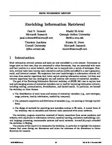
2. Framework for Enriching Animation Database The proposed framewaork consists of constructing a layered encapsulated animation database as depicted in figure 1. At the bottom layer Lr , only real animation clips exists. The middle layer Lm contains modifiers that generate new motion clips based on one or more real animation clip from Lr . The top layer Lv represents the virtual database that is available to user, which includes real and modified animation clips. Modifiers should be selected, designed, and implemented to be as simple and computationally efficient as possible.
†
[email protected] c The Eurographics Association 2004.
Layer ‘Lr’ [Real Animation Clips]
Layer ‘Lm’
Layer ‘Lv’ [Virtual Database]
[Modifiers]
Modified
Bi-Modifiers
clips
Modified
Uni-Modifiers
clips
Original clips
Figure 1: The Layered Animation Database diagram
However, the exact action of the modifier can be controlled by some parameters or attributes. Depending on the number of animation clips the modifier is accepting as inputs, there are uni-modifiers, bimodifiers, and multi-modifiers. Uni-modifiers are mainly basic animation processing techniques, such as “Mirror" and “RotatePath" (figure 2), that are applied on individual animation clips. Bi-modifiers use two input motions to generate a new one. Examples include speed, slope and path curvature control as depicted in figure 2. Multi-modifiers (or modules) are employing more than two input motions to produce new motion and can control more than one parameter simulteneously. This analogous, to some extent, to the motion models introduced in [Gra00]. The above modifiers use the parametric approach introduced in [AMH01]. Controlled by intuitive high-level motion paramters, from two or more given motions, the modifiers can produce varieties of motions which can be im-
A. Ahmed, F. Mokhtarian & A. Hilton / Enriching Animation Databases
practical to capture and store. Moreover, they are generated on demand (transparent to the user) and need not be saved permanently, which reduces storage requirements. The proposed layered database framework is expandable by defining new modifiers, cascading existing modifiers, or inserting real clips. Lr
Lm
A
A
∆Mj1
C3 θ4 C4
θ3
Mirror
Rotate Path M2
Mirror
∆Mj
∆Mi θj
θi
B
Lv
M1
∆Mi1
B
θ3 < θ4 and C3 < C4 (a)
∆Mj2
∆Mi2
(b)
Figure 3: Explanation of the Root Blending problems. a) Root translation magnitude is affected by the difference in direction between input motions. b) Root trajectory flips when moving from frame j (left) to frame i (right) with i > j and θ j < 180o < θi .
Rotate Path
Speed Control
Curvature Control
M3
Figure 2: Examples of enriching animation database contents In the light of the above framework, two novel contributions are introduced in the rest of this paper that allow for better utilisation of existing clips and greater reduction in the data requirements. 3. Improved Root-Trajectory Blending It is important to handle the root joint carefully because it influences the whole skeleton. Figure 3 explains two principal limitations of existing root blending which we successfully overcomed in our proposed technique. In figure 3.a, the magnitude of the blended root translation → − C is affected by the angle θ between the input motion direc→ − → − tions A and B . As a result, the overall motion parameters, such as speed, will be affected which reduces the accuracy of synthesised animation in terms of the desired parameter. Moreover, artifacts, such as foot slipping, will increase with the angle θ. The other problem, explained in figure 3.b, is the sudden flipping of the root trajectory when the angle θ changes around 180o (i.e from θ < 180o to θ > 180o ). An example of this problem is depicted in figure 4 where two curved-path motions are blended together. The blended motion suddenly turns back. The sudden flip in root position trajectory is inherited from vector analysis as depicted in figure 3.b. The resulting
Figure 4: The Synthesised root trajectory (middle) is suddenly flip to the opposite direction after the difference in direction of input motions exceeds 180o .
vector is always on the side of the smallest angle which suddenly changes around 180o . Hence the sudden flip of rootposition trajectory. In addition to the above, the sudden flip in root orientation is also attributed to the fact that a single orientation can be achieved by two different rotations (e.g., a rotation of 100o will lead to the same orientation of a rotation by −260o ). In our improved blending technique, the resulting root trajectories are built by blending the incremental changes in input root trajectories. This incremental approach allows us to preserve the magnitude of root translations and prevent the sudden flipping regardless of the global root position and orientation of the input motions. The incremental blending of the root orientation , with blending factor α, is achieved on the following steps (using quaternion interpolation): • The initial root orientation, at frame 1, is calculated by direct blending of root orientation of input motions. • For each frame i, calculate the accumulated root orientation Ri such as: Ri = Ri−1 + ∆Ri c The Eurographics Association 2004.
A. Ahmed, F. Mokhtarian & A. Hilton / Enriching Animation Databases
where and
∆Ri = α∆RiM1 + (1 − α)∆RiM2 i ∆RiM j = Ri−1 for j = {1, 2} M j − RM j ;
The incremental blending of the root translation, with blending factor α, is achieved on the following steps: • The initial root positions, at frames 1 and 2, are calculated by direct blending of root positions of input motions. • For each frame i > 2,
||X ji − X ji−1 ||2
for j = {1, 2}.
– Calculate the change in direction of root position trajectory for each input motion: i for j = {1, 2}; ∆θij = θi−1 j −θj where
θij
Z i −Z i−1 = tan−1 ( ij ji−1 ). X j −X j
– Check for sudden change in direction due to different representations of the same orientation (e.g. ±180o ) and compensate it: if (∆θij > 180o ) ∆θij = ∆θij − 360o if (∆θij < 180o ) ∆θij = ∆θij + 360o – Calculate the blended incremental change in direction of the root trajectory: ∆θi = α∆θi1 + (1 − α)∆θi2 – Calculate the global direction of the incremental root translation, relative to the global direction at last blended frame i − 1: θi = θi−1 + ∆θi → − – Calculate the global root position vector Pi by accumulating the incremental translation to the pre→ −i → → − − i−1 vious global position: P =P +∆ Pi (∆T i , θi ) Figure 5 presents the result of applying the improved root tra jectory blending on the example of figure 4. We can see that the improved blending technique has successfully avoided the problem of sudden flip of the root trajectory. From the example of figure 5, by allowing successful blend between motions of opposite path-curvature (and opposite directions such as straight and turn-back motions), the proposed improvement has allowed for syntheis of inbetween motions which were not achievable using the ordinary blend. Moreover, motion parameters, that depends on root translation such as speed, are preserved by maintaining the correct root translation within the proposed improvement as depicted in figure 6.a. The data requirements can be reduced further using the technique proposed in section 4. To the best of our knowledge, the only related work to this section is Kovar et. al [KC03]. Their proposed solution c The Eurographics Association 2004.
Original clip (left) and Synchronised Mirror clip (right) Figure 5: The synthesised root trajectory (middle) has no sudden flipping any more after using the improved blending technique. 120
Order of storage required
where ∆T ji =
Speed (cm/sec)
– For each input motion, calculate the magnitude of incremental root translation. ∆T i = α∆T1i +q(1 − α)∆T2i
100 80 60 40 20 0 0.0 0.9 0.8 0.7 0.6 0.5 0.4 0.3 0.2 0.1 1.0
Blending Factor Ordinary Blend
Improved Blend
(a)
40 35 30 25 20 15 10 5 0 0
2
4
6
8
10
Number of motion clips Kovar et. al.
Ours
(b)
Figure 6: Benefits of improved blending. a) Motion parameter (such as speed) is preserved. b) Storage requirements reduced.
is to align corresponding input motion frames, by applying 2D transformation in the floor-plane. The aligned frames are blended to produce the resulting frame posture and the 2D transformations are blended to produce the 2D transformation required to return the resulting frame to its global orientation. However, the rotation part of the 2D transformation can be done in both directions, clockwise and counterclockwise and there is no criteria for selecting the appropriate one for correct results in different situations. In our solution, blending the changes of input orientation avoids the large difference in direction between inputs. The history of one frame provides a clue for the change of direction of each input motion and allows for preventing sudden flip in root trajectory that may results from different representation of orientation. Also, instead of storing 2D transformation between every pair of corresponding frames for every pair of motions [KC03], we can save only the changes of direction for each individual motion. This reduces the storage requirements from O( m2 (m − 1)n) to O(mn), as shown in figure 6.b, where m is the number of motion clips and n is the number of corresponding frame pairs. 4. Synchronised Mirror Traditionally, mirroring of human animation is performed on the sagittal plane defined at the initial frame; the plane divid-
A. Ahmed, F. Mokhtarian & A. Hilton / Enriching Animation Databases
ing the human body vertically into two symmetrical halves, right and left. Traditional mirroring can double the number of clips in an animation database. However, the limitation is that the mirrored clips are out of phase with their original clips. For example, if the original clip is a ‘walk’ in a clockwise curved path starting with left foot ahead, its mirror will be a ‘walk‘ in a counter-clockwise curved path with the right foot ahead (instead of the left foot). This means that the key events of the motion are out of phase and blending between them will produce invalid motion (see accompanied animation examples).
Mcw
M
1
2
Mr
Our novel ‘SyncMirror’ technique achieves the goal of mirroring while producing motion that is in-phase with original motion. Given a curved-path motion cycle, say clockwise curvature Mcw , its synchronised mirror cycle Mccw can be obtained by applying the algorithm in figure 7 which is also explained by the diagram in figure 8. The algorithm mirrors a sequence of two cycles, constructed from the given cycle, which allows selecting the synchronised part of the mirrored cycle which is in phase with the given cycle.
M
3
4 Ms
Left foot has just touched the floor
Input: 1. One motion cycle ‘Mcw ’ on curved-path. (Cycle is assumed to have matched boundaries [AMH03].) 2. List of key-event times [T Mcw ]. Output: 1. Mirrored and Synchronised motion cycle ‘Mccw ’ Procedure: 1. Concatenate Mcw to its self M = Append(Mcw , Mcw ); 2. Mirror the 2 cycles clip Mr = Mirror(M); 3. Get the synchronised 1 cycle from ‘Mr ’ Ms = Mr [Ki : Ki+n ]; where Ki is the Key-event that in-phase with T Mcw (0) and n is one less the number of key-events per cycle. 4. Translate and rotate Ms to align with Mcw Mccw = T R ∗ Ms ; where T R is the appropriate transformation matrix. Figure 7: Synchronised Mirror algorithm, ‘SyncMirror’. The proposed SyncMirror algorithm can reduce data requirements to half. In figure 5, the only given clip is the clockwise curved-path motion (left). The counter-clockwise curved-path (right) motion is the synchronised mirror of the given motion. Inbetween motions, such as the straight-path motion (middle), are generated by blending both curved motions as discussed in section 3. 5. Conclusion The proposed enriching framework can reduce the data requirements by slightly modifying existing motions to generate variety of motions. Intuitively controlled motion varities
Mccw
Mcw
Right foot has just touched the floor
Figure 8: This diagram explains the synchronised mirror algorithm, ‘SyncMirror‘ of figure 7
are generated on demand which reduces the storage requirements, avoid recapturing missing variations, and provide more flexibility. The improved root − tra jectory blending and the novel synchronised mirror techniques allow for greater utilisation of existing clips as depicted in figure 5. Using the proposed techniques, all clips in the Lv layer of figure 2 can be generated from only one clip such as M1 . Animation examples are enclosed in the accompanied archive. References [AMH01] A HMED A., M OKHTARIAN F., H ILTON A.: Parametric motion blending through wavelet analysis. In Eurographics’01. Proceedings of Short Presentations (2001), pp. 347–353. 1 [AMH03] A HMED A., M OKHTARIAN F., H ILTON A.: Cyclification of human motion for animation synthesis. In Eurographics’03. Proceedings of Short Presentations (2003), pp. 193–200. 4 [Gra00]
G RASSIA F. S.: Believable Automatically Synthesized Motion by Knowledge-Enhanced Motion Transformation. PhD thesis, School of Computer Science, Carnegie Mellon University, Pittsburgh, 2000. 1
[KC03]
KOVAR L., C LEICHER M.: Flexible automatic motion blending with registration curves. In Proceedings of the SIGGRAPH Symposium on Computer Animation (2003). 3 c The Eurographics Association 2004.