Journal of Automation and Control Engineering Vol. 2, No. 1, March 2014
Equalizing Converter Utilization Using a Fuzzy Decision Mechanism based on Input Voltage Perturbation and Time of Usage Mark Ryan S. To and Elmer R. Magsino Electronics and Communications Engineering Department,Gokongwei College of Engineering, De La Salle University - Manila, Taft Avenue, Philippines Email: {mark.ryan.to, elmer.magsino}@dlsu.edu.ph
Jessica C. Cabiles – Magsino Electrical and Electronics Engineering Institute, University of the Philippines – Diliman, Philippines Email:
[email protected]
Paralleling DC-DC converters has many desirable advantages including reliability due to redundancy, flexibility due to modularity, and stability due to reduced thermal stress since each module handles a lower power level [1]. Paralleled power supplies are also widely used to provide current sharing capabilities for high current applications. However, special provisions are considered when paralleling converters. There are also a variety of approaches and techniques that have been proposed and implemented. In this paper, the average current-mode control method was used for the paralleled buck converters. The advantages of average current mode control, such as the ability to control the average inductor current and the improvement of noise immunity by using a current compensator has already been investigated [2]. Digital control has become increasingly used in power switching converters mainly because it offers the potential advantages of immunity to noise due to analog component variations and other factors that can degrade the performance of the converters. Digital control of parallel DC-DC converters was already modelled by Taufik et al. [3] to achieve load sharing but the model was done based on efficiency through a look-up table implementation and not based on converter specifications. Fuzzy logic applications to power electronics and drive (PE&D) have been increasing exponentially in the past few years. However it has been criticized in spite of its practical success due to its limitations such as the lack of a formal design methodology and difficulty in predicting stability and robustness of the fuzzy logic controllers. Because of this, considerable effort has been devoted to solve these issues. In this paper, a fuzzy logic controller was used to improve the elementary and simplified control proposed earlier in a previous study [4-5]. It was shown that the elementary control turns ON each converter in sequence from converter 1-4 with the first converter, the most frequently used converter. The disadvantage posed by this control is that it always has the first converter turned ON with the fourth converter the least frequently operated converter. This induces tremendous stress on the first converter. Practically, with
Abstract—In this paper, fuzzy logic was used to provide the information on the probability of turning ON of four parallel converters using the converter utilization parameter and the input voltage perturbation. Each converter is designed having equal values of inductances and capacitances but with different parasitic resistances and was modelled using MATLAB/Simulink environment. Based on the output probabilities, the appropriate converter/s to turn ON will be turned ON by an enable circuit written in MATLAB code resulting to a well-balanced utilization of all converters. The specified input voltage of each converter is set to be 20 volts with different variances. Since each converter utilizes different supply voltages, the supply voltage is fed to a Gaussian noise realized through a random generator block to provide the variance around 20 volts. The voltage and current errors of each converter were sampled and fed into a discrete controller to regulate its output voltage. Between active converters sharing the load, the average current sharing/ democratic sharing method was used. In this paper, it was found that the fuzzy logic controller can be used to control parallel digital converters to properly balance converter utilization. Simulation results are presented including the static and dynamic loading responses. Index Terms—DC-DC buck converters, current-sharing, digital control, fuzzy logic, democratic current sharing
I. INTRODUCTION Even in a developed world, most technologies still rely on power supplies, ranging from a simple phone charger to a laptop power supply to electric-powered vehicles. With the development on industries such as telecommunications, computer and networks systems and information technology, the market for power supplies is growing even larger. The power supply unit is a critical part in most technologies since most components are sensitive and require exact voltage at certain load conditions from the power supply.
Manuscript received March 5, 2013; revised September 7, 2013. ©2014 Engineering and Technology Publishing doi: 10.12720/joace.2.1.79-83
79
Journal of Automation and Control Engineering Vol. 2, No. 1, March 2014
regard to housekeeping, the first converter will likely be the first to fail. In most literature, fuzzy logic is commonly used as a controller to make sure the output voltage is robust against load disturbances while having the output currents very well equalized [6], to improve the current sharing of input-series and output-parallel connected converter [7], to reduce the switching losses in a static converter when is switched at high frequency [8], and to achieve the stable voltage regulation and uniform current distribution among converters [9-10]. On the other hand, this paper employed a fuzzy logic controller to address the issue of unbalanced utilization of paralleled converters by having the controller output the probabilities of each converter/s that is/are best to turn ON based on converter utilization and input voltage changes. Section II provides a discussion on the methodology of how the Simulink model was improved from the elementary and simplified control, the development of the fuzzy logic controller, and the MATLAB code used for converter enables. Section III presents the discussion of the results obtained from the Simulink Model.
A. Current Sharing and Converter Utilization Using Traditional and Elementary Methods The current set-up for current sharing of converters is that each converter is interconnected such that when a load is placed on the output, each converter is turned ON and all converters share to drive the common load. However, it is more advantageous and more practical if only a certain number of converters will be operated given that it can support the required current to drive the load. This was realized in an earlier work using a control labeled as elementary and simplified control [4] and [5]. Using this control method, the right number of converters is/are turned ON depending on the maximum output current specification of the converters and the output current requirement to be driven. An earlier work has highlighted the disadvantage of the elementary control method [12]. The disadvantage posed by the elementary control method is that the turning ON of converters is always done sequentially starting with converter 1. In a set-up of four converters connected in parallel, when two converters are required to turn ON, only the first two converters (converters 1 and 2) are turned ON. It can be easily seen that the last converters (3 and 4) are less utilized leaving the first converters in line to a higher probability of failure in the long run.
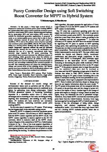
II. MODEL DEVELOPMENT OF THE FUZZY CONTROL OF PARALLEL BUCK CONVERTERS Each of the four buck converters connected in parallel follows the model shown in Fig. 1. Each converter was designed to have a switching frequency of 100 kHz, an input voltage (Vg) of 20Vdc, a regulated output (Vo) of 12Vdc and a maximum current output (Iout) of 2.5A. Regulation was done using the average current mode control scheme. The values for the inductor, capacitor, and parasitic series resistances for the buck regulator were designed with the following specifications below as shown in Table I. It can be noticed that all converters almost follow the same specifications with only differing ESRs since modularity must be observed between paralleled converters.
B. Fuzzy Logic Controller (FLC) A fuzzy logic controller was used to improve the elementary and simplified control. As previously discussed, the elementary and simplified control poses the disadvantage of imposing a higher stress on the first converter because of utilization imbalance. A fuzzy logic control was developed in order to address this issue. The first step in designing a fuzzy controller is the selection of the controller inputs and output. Moreover, choosing the appropriate linguistic variables formulating the fuzzy control rules are also as important in the determination of the performance of the fuzzy control system. The fuzzy controller is composed of four elements namely: fuzzification, rule base, inference mechanism and defuzzification. The fuzzification interface translates the crisp inputs into fuzzy membership values used in the rule base. Converter utilization and input voltage perturbation were chosen as the fuzzy controller crisp inputs with the probability of turning ON as the controller defuzzified output. After choosing the linguistic variables of the controller, the derivation of the fuzzy control rules was developed. Fuzzy control is characterized by a collection of fuzzy IF-THEN rules in which the preconditions and consequents involve linguistic variables. The rule base consists of a tabulated data which contains information related to the system and the inference mechanism emulates the decision making in controlling the plant. The rule base in the fuzzy logic controller can be represented as: If {Utilization (%)} and {Input/supply voltage (V)}, Then {Probability (P) where utilization (%) and input voltage (Vin) represent the preconditions and the probability represents the
Figure 1. Buck converter topology [11] TABLE I. CONVERTER SPECIFICATIONS Converter 1:
L = 49.08 μH, ESR = 0.1Ω C = 153.4 μF, ESR = 0.01Ω
Converter 2:
L = 49.08 μH, ESR = 0.08Ω C = 153.4 μF, ESR = 0.03Ω
Converter 3:
L = 49.08 μH, ESR = 0.05Ω C = 153.4 μF, ESR = 0.02Ω
Converter 4:
L = 49.08 μH, ESR = 0.09Ω C = 153.4 μF, ESR = 0.01Ω
©2014 Engineering and Technology Publishing
80
Journal of Automation and Control Engineering Vol. 2, No. 1, March 2014
simply from 0 to 1. In this study, the singleton fuzzification with triangular membership functions, center-of-gravity defuzzification and product fuzzy inference were adopted. Fig. 2 shows the surface view of the fuzzy logic system of each controller. Isolating Vin, it can be noticed that the Utilization versus probability plot shows that as the Utilization decreases, the probability of turning ON increases. On the other hand, isolating utilization input, the Vin versus probability plot resembles a Gaussian curve with its peak at an input voltage of 20 volts which is the specified input voltage of each converter. The probability of turning ON decreases correspondingly when the input voltage increases or decreases from the specified input voltage.
consequent or the fuzzy set (singleton action). The derivation of the rules are based on the fact that when converter utilization is low and the input voltage is OK or exact, the probability for a converter to turn ON is highest. Depending on the lowness or highness of converter utilization and input voltage perturbation, the corresponding output probabilities are shown in the fuzzy rule base in Table II. The first input represents converter utilization where L (low), L-M (low to medium), M (medium), M-H (medium to high) and H (high) represent the degree of utilization. The second input is input voltage where V-L (very low), U-L (under-voltage), OK (good or exact), OV (over-voltage), and V-H (very high) represent the degree of perturbation. TABLE II. FUZZY RULE BASE Utilization Vin V-L UV OK OV V-H
L
L-M
M
M-H
H
HP VHP VVHP VHP HP
P HP VHP HP P
LP P HP P LP
VLP LP HP LP VLP
VVLP VLP LP VLP VVLP
The range for the utilization input ranges from 0-100% and the range for the input voltage perturbation is from 15-25 volts. Since the output is a probability, the range is
Figure 2. Surface view of the fuzzy logic system
Figure 3. Simulink model of the fuzzy logic control of 4 parallel dc-dc converters with a matlab function for converter enable
Fig. 3 shows a hierarchical view of the Simulink model of the Fuzzy Logic Control of 4 parallel DC-DC converters with a MATLAB function for converter enables. The fuzzy logic controller block contains the four fuzzy logic controllers for each converter module with the inputs of converter utilization and input voltage perturbation and with the probability of turning ON as the
©2014 Engineering and Technology Publishing
output. The MATLAB function contains the MATLAB code that utilizes the output of the fuzzy logic controller as inputs with the enables as its outputs. The output enable is then fed onto the paralleled converter module block which contains four paralleled converter modules interconnected using the average current mode (ACM) control method, to turn ON/OFF the corresponding
81
Journal of Automation and Control Engineering Vol. 2, No. 1, March 2014
converters. The enable output is also connected to the utilization blocks which is responsible for monitoring converter utilization which is an information used by the fuzzy logic controller. To solve the problem of circularity of information since the input (utilization) is also dependent on the output (enable), unit delay blocks were used to provide an initial condition of utilization equal to zero.
3 continually decrease. At t=0.05, all the utilizations of all the converters converge at 25%. It is also shown that as the converters continue to operate, utilization converges at 25% periodically. Thus, utilization is shared equally among four converters.
III. EXPERIMENTAL RESULTS AND DISCUSSION Using the Simulink model discussed above, simulations were performed to verify the performance of the parallel buck converters with a fuzzy logic controller that outputs the probability of turning ON a converter. Four converters were paralleled to give the total system a power rating of 120 watts. The first testing includes a static loading of 2A to test the ability of the fuzzy logic controller and the enable circuit to properly distribute the utilization among four converters. Fig. 4 shows the different voltage inputs of each converter used in the static and dynamic loading testing. The input voltage is 20 volts fed into a Gaussian noise with variances of 1, 0.75, 0.5 and 0.25 respectively.
Figure 5. Converter utilization under static loading of 2a
In a previous work [12], utilizing the same set-up with a constant input voltage, the same result of convergence to 25% utilization was achieved using a constant input voltage. In this test, due to the perturbation in the input voltage, converter 3 was first turned ON in contrast to the constant input voltage testing in which converter 1 was turned ON first. This is due to the fact that the change in input voltage is taken into account by the fuzzy logic controller.
Figure 4. Input voltages of each converter
Using the fuzzy logic controller and the enable circuit, converter utilization was balanced out among the four converters as seen from Fig. 5. The simulation was done for 0.2 seconds with a sample time/refresh rate of 0.0125 seconds. As seen from Fig. 5, from t=0 to t=0.0125, converter 3 has a utilization of 100% while the other converters have a utilization of 0%. During the next sample time, a new set of probabilities are taken from the output of the fuzzy logic controller causing the MATLAB enable circuit to produce a new set of combination for the enables. From t=0.0125 to t=0.025, converter 1 is turned ON, causing a rise in its % utilization while the utilization of converter 3 starts to decrease. From this period, the utilization of converters 2 and 4 are still maintained at 0%. From t=0.025 to t=0.0375, converter 2 is turned ON, causing a rise in its % utilization while the % utilization of converter 1 and 3 starts to decrease. From this period, only the % utilization of converter 4 remains at 0%. Finally, from t=0.0375 to t=0.05, converter 4 turns ON, causing a rise in its utilization while the utilizations of converters 1-
©2014 Engineering and Technology Publishing
Figure 6. Corresponding output voltage and current sharing outputs, Iox under static loading of Itot = 2A
Fig. 6 shows the regulated output voltage at 12 volts and the corresponding output currents of each converter under a static loading of 2 amperes. Since the output current requirement can already be satisfied by only a single converter, there will be no current sharing error among the converters. Under static loading, the equation to determine at which utilization all converge is determined by equation 1.1 where UC is the utilization all converters will converge, N is the number of paralleled converters, Iout is the current output demand and Io (max) is the maximum output current that can be delivered by each converter.
82
Journal of Automation and Control Engineering Vol. 2, No. 1, March 2014
[2] B. H. Cho, H. S. Bae, and J. H. Lee, “Review of current mode
(1) [3]
The second set of testing includes an output current pattern of 10-2-6-3A to test the dynamic loading performance of the system while still being able to maintain equal converter utilization. Figure 7 shows the converter utilizations under dynamic loading. Even with the effects of varying input voltage, it can be seen that the converter utilizations are still able to balance out periodically. The converter utilizations first balance out at 66.66% and then balance out at 62.50%
[4] [5] [6]
[7] [8] [9] [10] [11]
[12] Figure 7. Converter Utilization under dynamic loading of 10-2-6-3A
Mark Ryan S. To was born in Manila, Philippines. He earned his bachelor’s degree in Electronics and Communications Engineering from De LaSalle University-Manila on 2010 in Manila, Philippines. He is now pursuing his Master’s degree in Electronics and Communications Engineering from the same university. He serves as a part-time instructor in the Computer Engineering and Electronics and Communications Engineering Department in the same university. He is a graduate student member of IEEE and has published papers in the field of power electronics specifically on the topics of current-sharing and control of DC-DC Converters
IV. CONCLUSION This paper has successfully verified that with the use of a fuzzy logic controller the issue of unbalanced converter utilization among converters can be addressed. MATLAB/Simulink simulations illustrated the effectiveness of the proposed scheme. Static and dynamic loading were done to test the system model developed in Simulink. The output voltage was regulated all throughout the simulation with the converter utilization being able to balance out. Under a static loading of 2A, four converters shared the output current requirement equally to have a utilization of 25% each. It was noted that compared to a similar testing using a constant input voltage, converter 3 was the first converter to turn ON instead of converter 1 in the set-up with varying input voltage because the input voltage perturbation was taken into account by the fuzzy logic controller. To improve the proposed system, further tuning can be done to the fuzzy controller specifically on the effects of input voltage perturbation. More membership functions or an adjustment to the current membership functions can be solutions to this problem as it can provide more categories to better represent each range. This will help the fuzzy controller provide a better estimate probability for each converter.
Elmer R. Magsino earned his Bachelor of Science in Electronics and Communications Engineering and Master of Science in Electrical Engineering at the University of the Philippines – Diliman, Philippines in 2002 and 2006 respectively. His research interests concern linear and non-linear control systems, signal processing and Mechatronics. He is currently an Assistant Professor at the De La Salle University – Manila Philippines and is currently pursuing his PhD in Electronics and Communications Engineering. Prof Magsino is currently a graduate student member of the IEEE and member of the Science and Engineering Institute. Jessica C. Cabiles – Magsino earned her Bachelor of Science Science in Electronics and Communications Engineering at St. Louis University – Baguio and Master of Science in Electrical Engineering at University of the Philippines Diliman, Philippines in 2003 and 2012 respectively. Her current research interests include power electronics exploring both analog and digital control applications. She is currently a Design Engineer under the Advanced Engineering department of Emerson Network Power at Quezon City Philippines focusing on digitally controlled power converters.
REFERENCES [1] J. Sun, “Dynamic performance analyses of current sharing control for dc/dc converters,” dissertation, Virginia Polytechnic Institute and State University, 2007.
©2014 Engineering and Technology Publishing
control schemes and introduction of a new digital current mode control method for the parallel module dc-dc converters,” in Proc. 2009 IPMEC, vol. I, pp. 202-210. T. Taufic, D. Dolan, and R. I. Putri, “Digital control of parallelconnected dc-dc converters,” in Proc. 2011 ITNG, IEEE, vol. I, pp. 772-776. M. R. To and E. Magsino, “Elementary and simplified control of digital parallel buck converters,” in Proc. ICCSCE, IEEE, 2012. M. R. To and E. Magsino, “Elementary and simplified control of analog parallel buck converters,” in Proc. RCICT, pp. 72-75. Y. L. Peng, C. Cheng, C. Zheng, and E. Chang, “DSP-based control of parallel dc-dc boost converters by adaptive fuzzy sliding-mode control scheme,” in Proc. ICGEC, IEEE, 2012, pp. 130-133. S. Khazraei, A. Rahmati, and A. Abrishamifar, “Fuzzy-linear control of an input-series and output-parallel dc-dc converter,” in Proc. ICIT, IEEE, 2008, pp. 1-5. H. Chamorro and C. Trujillo, “Switching losses analysis of a dc link fuzzy logic controller scheme applied to a VSC,” in Proc. NAPS, IEEE, 2009, pp. 1-6. R. Wai and Y. Chen, “Automatic fuzzy control design for parallel dc-dc converters,” in Proc. IMECS, vol. 1, pp. 1-6. B. Tomescu, “Adaptive stable fuzzy logic control for parallel dcdc converters current sharing,” in Proc. PESC, IEEE, vol. 3, 2001, pp. 1270-1276. Colorado Power Electronics Center. Introduction to matlab/simulink for switched-mode power converters. (June 12, 2012). [Online]. Available: http://ecee.colorado.edu/~ecen5807/course_material/digital/5807_ Simulink_tutorial.pdf M. R. To, “A novel fuzzy-supervised controller for digital parallel buck converters for balanced converter utilization,” M. S. thesis, Electronics and Communications Engineering Department, De La Salle University, Manila, Philippines, 2013.
83