load) has been adopted in some building design codes such as the draft Eurocode ..... normalized PSD of wind fluctuation with respect to its mean square value.
Equivalent Static Wind Loading on Buildings: A New Perspective Xinzhong Chen and Ahsan Kareem NatHaz Modeling Laboratory, University of Notre Dame, 156 Fitzpatrick Hall, Notre Dame, IN, USA
ABSTRACT: A framework for evaluating the equivalent static wind load (ESWL) for any given peak response of buildings characterized by uncoupled motions in the three primary directions is presented. This includes a new description of the background loading based on the gust loading envelope, whereas the resonant component is described in terms of the inertial loading. The ESWL for the total peak response is then expressed as a linear combination of the background and resonant components. A closed-form formulation of the ESWL based on this framework utilizing an analytical wind loading model is presented. The gust response factors and ESWLs for various alongwind response components at different building elevations are discussed to highlight advantages of the proposed scheme. KEYWORDS: Wind loads, Wind effects, Gust response factor, Buildings, Structural dynamics, Random vibration. 1 INTRODUCTION In current design practice, spatiotemporally varying wind loads on buildings are modeled as equivalent static wind loads (ESWLs). Traditional gust response factor (GRF) approach (Davenport 1967) is widely used in most building design codes and standards for the alongwind response that results in a load distribution similar to the mean wind load (e.g., Zhou and Kareem 2001). The GRF concept has been extended to the acrosswind and torsional response components (Piccardo and Solari 1996; Kareem and Zhou 2002). However, the GRFs may exhibit wide variations for different response components of a structure and may have significantly different values for structures with similar geometric profiles and associated wind load characteristics, but different structural systems. For the acrosswind and torsional responses, which are typically characterized by the low values of mean wind loading and associated response, particularly, for symmetric buildings, the corresponding GRFs may not project the same physical meaning as the traditional GRF for the alongwind response. An ESWL description based on the peak dynamic pressure/wind load (including the mean load) has been adopted in some building design codes such as the draft Eurocode (ENV-1991), ASCE7-02 and the new Australian/New Zealand Standards (Holmes 2002). This format describes the ESWL as the peak dynamic load multiplied by a constant coefficient referred to as dynamic response factor (DRF) (Holmes 2002). In Solari and Repetto (2002), an identical ESWL distribution for all response components was suggested. They utilized a polynomial expansion, which was obtained on the premise that the selected ESWL resulted in accurate estimates of a limited number of pre-selected peak response components. Separation of wind loads and their effects and the associated ESWLs into background (quasi-static) and resonant components provides not only an efficient response prediction
framework but also a physically meaningful description of the loading (Davenport 1985; Kasperski 1992; Holmes 2002; Isyumov 1999; Zhou et al. 2000; Zhou and Kareem 2001; Chen and Kareem 2001). Accordingly, the resonant ESWL (RESWL) can be expressed in terms of the inertial load (e.g., Davenport 1985). Whereas the background ESWL (BESWL) depends on the external wind load characteristics and can be determined using a Load-Response-Correlation (LRC) approach (Kasperski 1992), which provides a most probable load distribution (Kasperski 1992 and Tamura et al. 2002). Based on the BESWL and RESWL, the corresponding peak resonant and background responses can be calculated using a simple static analysis. These are then combined using the complete quadratic combination (CQC) approach or the square root of the sum of squares (SRSS) scheme for the total peak response (excluding the mean component). Alternatively, an ESWL for the total peak response can be expressed as a linear combination of the background and resonant loading components (Chen and Kareem 2001; Holmes 2002). In this paper, a framework is presented for evaluating the ESWL for any given peak response component of wind-excited buildings characterized by uncoupled motions in the three primary directions. A new description of the BESWL is presented based on the gust loading envelope (peak dynamic loading without the mean component). The RESWL is given in terms of the inertial load in each fundamental mode. The ESWL for the total peak response is then expressed as a linear combination of the BESWL and RESWL. Based on this framework, a closed-form formulation of the ESWL using an analytical wind loading model is presented. The GRFs and ESWLs for various alongwind response components at different building elevations are discussed to highlight advantages of the proposed ESWL description. 2
GENERAL FORMULATIONS
The response of a wind-excited building with one dimensional uncoupled mode shapes in the two orthogonal translational and torsional directions at a given wind speed and direction is considered. The wind loads per unit height at elevation z above the ground have mean components of Px (z ) , Px (z ) and P (z ) , and fluctuating components of Px ( z , t ) , Py ( z , t ) and P ( z , t ) , in the translational axes x and y and about the vertical axis z. The discussion here is focused on the response with one dimensional influence functions in the three primary directions. The uncoupled class of response in the three primary directions permits treatment of wind loading and building response in each direction independently. Without loss of generality, the following discussion will focus on translational response in the x direction at a given wind speed and orientation; a similar treatment in other directions is immediate. For a specific response of interest (displacement, bending moment, shear force and other member forces) at a building elevation z0, R(z0, t), the mean (static) and background components can be calculated by the static and quasi-static analysis. The resonant component can be analyzed using modal analysis restricted to the fundamental mode. The mean response, root mean square (RMS) background and resonant responses and the peak dynamic response (excluding the mean response) are expressed as
R=
H 0 H
Rr
=
0
Px ( z ) µ x ( z )dz; m( z ) H 0
x
m( z )
Rb
=
( z ) µ x ( z )dz 2 x
4
( z )dz
SQ x ( f ) =
H
H
0
0
x
H
H
0
0
µ x ( z1 ) µ x ( z2 ) RP ( z1 , z2 )dz1dz2
f1SQ x ( f1 ) ;
xx
Rmax = g b2
2 Rb
+ g r2
2 Rr
(1) (2)
1
( z1 )
x
( z2 ) S Pxx ( z1 , z2, f )dz1dz 2
(3)
where H= building height; µx(z)= influence function indicating the response R(z0,t) under unit load acting at the elevation z in x direction; x(z)= fundamental mode shape; f1 and 1= fundamental frequency and damping ratio (including aerodynamic damping), respectively; m(z)= mass per unit height; RPxx ( z1 , z2 ) and S Pxx ( z1 , z2 , f ) = covariance and cross power spectral density (XPSD) between Px(z1,t) and Px(z2,t); SQx ( f ) = power spectral density (PSD) of the generalized modal force; gb and gr= peak factors for the background and resonant responses, respectively, typically ranging in value between 3 and 4. Following the LRC approach (Kasperski 1992), the BESWL for peak background response, g b Rb , is given by
FeRb ( z ) =
gb
H 0
Rb
µ x ( z1 ) RP ( z, z1 )dz1
(4)
xx
which depends on the influence function of the response under consideration. Accordingly, the BESWL has a different spatial distribution for different response components, which may not be very attractive for code applications. For the purpose of simplifying the background load description, it is proposed here to ' ( z ) = g b RPx ( z ) , multiplied by a express the BESWL as the gust loading envelope (GLE), Febx background factor, Bz, ' FeRb ( z ) = Bz Febx ( z );
Bz =
Rb
/
' Rb
;
' Rb
=
H 0
' µ x ( z ) Febx ( z )dz
(5)
where RPx ( z ) = RPxx ( z , z ) ; g b R' b = peak background response under the loading envelope that does not include the influence of loss in spatial correlation of wind loading over the building height; Bz represents the reduction effect with respect to the response R(z0,t) due to loss of correlation of wind loading. In cases where the wind loads are fully correlated, i.e., R Pxx ( z1 , z 2 ) = R Px ( z1 ) R Px ( z 2 ) , Bz becomes unity and the BESWLs based on the LRC and GLE ' schemes converge to the gust loading envelope, Febx ( z) .
The RESWL for the peak resonant response, g r Ferx ( z ) =
g r m( z ) H 0
m( z )
x 2 x
Rr
( z)
( z )dz 4
, is given in terms of the inertial load:
f1SQ x ( f1 )
(6)
1
which can also be expressed in terms of the distribution of the peak base bending moment or base shear force over the building height following the inertial load distribution. When the torsional response is under consideration, the RESWL is obtained by distributing the base torque over the building height. The ESWL for the total peak dynamic response, Rmax , can be provided as a linear combination of the background and resonant loads (Chen and Kareem 2000 and 2001; Holmes 2002): ' FeR ( z ) = Wb Bz Febx ( z ) + Wr Ferx ( z ) ; Wb = gb Rb / Rmax ; Wr = g r Rr / Rmax (7) When the peak response includes the mean component, the ESWL is given as Px ( z ) ± FeR ( z ) .
(
)
3 CLOSED-FORM FORMULATION For the sake of illustration, the mass per unit height, m(z), the first mode shape, influence function of the response R(z0,t), µx(z), are expressed as z ); H
z x ( z) = H
µ x ( z ) = µ0
z
z0
x(z),
and the
0
( z z0 ) (8) H 0 ( z < z0 ) where m0= the mass per unit height at the bottom of the building; = a constant parameter (0 1); and = mode shape exponent ranging between 1.0 and 1.5 for typical buildings; µ0 and 0= constant parameters. For the top displacement, µ0=i0, z0=0, and 0= ' (where i0 is the deflection at the top of the building under a unit load at that point; '= a constant parameter); for the bending moment at height z0, µ0=H and 0=1; and for the shear force at height z0, µ0=1 and 0=0. The XPSD and covariance of wind load per unit height are assumed as k f z z S ( f ) z1 z2 exp( z 1 2 ) (9) S Pxx ( z1 , z2 , f ) = P 2 H H H UH m( z ) = m0 (1
RPxx ( z1 , z 2 ) = where
2 Pb
=
f 0
2 Pb 2
H
z1 H
;
z2 H
z1 z 2 ) Lzx
exp(
(10)
'
S P ( f )df
0
S P ( f )df ( f '
f1 ) ; S P ( f ) = PSD of wind load at the building top
normalized by H2; UH= mean wind speed at the building top; = wind load profile coefficient; Lzx = integral length scale of the fluctuating wind load; kz= decay factor in the vertical direction. The BESWL based on the GLE approach and the RESWL are expressed as z z g b Pb z ' FeRb ( z ) = Bz ( , 0 , 0 ) Febx ( z ) = Bz ( , 0 , 0 ) (11) H H H H Ferx ( z ) =
J z ( , , f ) gr (2 + 1)(2 + 2) [(2 + 2) (2 + 1)] (1 + + ) H
4
f1S P ( f1 ) (1 1
z z ) H H
(12)
where Bz2 ( , 0 , z0 / H ) and | J z ( , , f ) |2 are the background factor and joint acceptance function that represent the load reduction effects due to the loss of vertical spatial correlation in wind loads, and can be approximated by 1 z 1 2 Bz2 ( , , 0 ) ; (13) Jz ( , , f ) z 1 + ( H z0 ) / Lx /(2.5 + 0 ) H 1 + k z fH / U H /(2.5 + ) It is noted that both Bz2 and |Jz|2 become unity when wind loads are fully correlated over the 0 and k z fH / U H 0 , and decrease with decrease in the building height, i.e., H / Lzx correlation/coherence. 4 ALONGWIND LOADING AND RESPONSE In order to highlight the advantage of the ESWL based on the external wind loading and modal inertial loads in comparison with that based on the traditional GRF approach, the following discussion is focused on the alongwind response, i.e., the response in the translational direction, x, for wind approaching at zero angle of incidence. Assuming that the mean wind speed varies according to the power law as U(z)=UH (z/H) , and the drag coefficient, aerodynamic admittance
function and turbulence intensity are uniform over the building height, the mean wind load per unit height is given by Px ( z ) = qH / H ( z / H ) 2 . The XPSD and covariance of wind load per unit height are given by Equations (9) and (10) with Lzx = Lzu = integral length scale of alongwind fluctuation and S P ( f ) = 4qH2 I u2 Su* ( f ) | ! D ( f ) |2 | J y ( f ) |2 (14) where qH = 0.5"U H2 CD BH ; = air density; B= building width; CD= drag coefficient; Su* ( f ) = Su 0 ( f ) / u20 = normalized PSD of wind fluctuation with respect to its mean square value 2 u0
=
0
Su 0 ( f )df ; I u =
u0
/ U H = turbulence intensity at the top of the building; | D(f)|2=
aerodynamic admittance function; and |Jy(f)|2= joint acceptance in the horizontal direction given by |Jy(f)|2=(2/ y)[1-1/ y+(1/ y)exp(- y)] and y=kyfB/UH; and ky= decay factor in horizontal direction. Detailed closed-form expressions for the top displacement, bending moment and shear force at a given elevation z0 can be obtained. The background and resonant GRFs (BGRF and RGRF) for any response component at any building elevation can be calculated as the ratio of the peak background and resonant components with respect to its mean value. For example, the BGRF and RGRF for the top displacement (z0=0 and 0= '), base bending moment (z0=0 and 0=1) and base shear force (z0=0 and 0=0) are given by the following general expressions: f1 g 2 (1 + 2 + 0 ) 2 gb Iu 2 Gb = b Rb = Su* ( f ) ! D ( f ) J y ( f ) df (15) z 0 R (1 + + 0 ) 1 + H / Lu /(2.5 + 0 ) Gr =
gr
Rr
R
=
[( + 0 + 2) ( + 0 + 1)] (2 + 2)(2 + 1) (1 + 2 + 0 ) ( + 0 + 2)( + 0 + 1) [(2 + 2) (2 + 1)] (1 + + ) 2 g r Iu 1 + k z f1H / U H /(2.5 + )
4
f S ( f1 ) ! D ( f1 ) J y ( f1 ) * 1 u
2
(16)
2
1
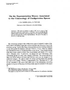
5 DISCUSSION In order to highlight the dependence of GRF on the response under consideration, Figure 1(a) shows the ratio of BGRFs for the top displacement ( '= 0=1.5 as an example) and the base shear to the BGRF for base bending moment. Figures 1(b) and (c) compare BGRFs for shear and bending moment at different elevations, respectively, normalized by the BGRF for base shear and base bending moment, respectively. Figure 2 shows the corresponding comparison results for the RGRFs. It is noted that the differences among the BGRFs for base bending moment, base shear and top displacement are marginal and are within 5%. Their influence on total peak responses will become less significant when the resonant components are included. However, the BGRFs for shear force and bending moment increase markedly with increasing elevation. This is due to the rapid increase in the equivalent loads for responses at higher elevations as compared to the mean load. It is obvious that using the BGRF based equivalent loading associated with either base bending moment, base shear or top displacement, which follows a distribution similar to the mean wind load, will significantly underestimate the background responses at higher elevations. On the other hand, as indicated in Figure 2(a), the RGRF for the base shear force is remarkably different from those for the base bending moment and the top displacement. As shown in Figures 2(b) and 2(c), the variations in RGRFs with elevation may be significant. This
is due to the fact that the actual equivalent load distribution in terms of the inertial load may significantly deviate from the mean load distribution. Again, using the RGRF based equivalent load associated with the base bending moment or base shear or top displacement will introduce noteworthy errors in predicting other resonant responses at different elevations.
=1.5
0
0.8
0.8
0.6
0.6
0
z /H
x
GbR(0)/GbM (0)
1.05
1
z0/H
1.1
1
1
0.4
0.95
0
H/Lz=2 x H/Lz=4 x H/Lz=6 x
0.2
2
4
H/Lz
6
=0.2 =1
0
=0.2 0.9
0.4
=0.2 =0
=0
0
8
10
0 0.8
0.2
1 1.2 1.4 GbF (z )/GbF (0)
x
x
(a)
0
0 H/Lz=2 x z H/L =4 x H/Lz=6 x
0 0.8
1.6
1 1.2 1.4 GbM (z )/GbM (0)
x
x
0
(b)
1.6
x
(c)
Figure 1. Comparison of the BGRFs, (a) base shear force, base bending moment and top displacement, (b) shear forces at different elevations, (c) bending moments at different elevations
0.8
0.6
0.6
0.9
0
z0/H
/G
0.8
=0 =0.2 =0 0
0.4
=0
0
0.8
0.2
1
1.5
0
2
1
0
0.2
1.5 GrF (z )/GrF (0) x
(a)
0
=0 =0.2 =1
0.4
=1.0 =1.2 =1.5
=0.2, =0 0.7 0.5
z /H
1
rR(0)
G
1
=1.5 0
x
rM (0)
1.1
1
0
2
=1.0 =1.2 =1.5 1
1.2 G
/G
rM (z )
x
x
0
(b)
1.4
1.6
rM (0) x
(c)
Figure 2. Comparison of the RGRFs, (a) base shear force, base bending moment and top displacement, (b) shear forces at different elevations, (c) bending moments at different elevations 1
1
0.8
0.8
0.8
(z/H)
0
=0 =1 0 =1.5
0.6
0.6 =0.2 H/Lzx=4 =0
0.4
0.2
0.5 1 FeR (z)/(gb P )H b
b
(a)
=0.2 H/Lz=4 x =1
0
0.4
z0/H=0 z0/H=0.4 z /H=0.8
0.2
0
1.5
0
0
0.5 F (z)/(g eR
b
1
b P
)H
b
(b)
0.6 =0.2 =1 z /H=0
0.4
0
0 z
z0/H=0 z0/H=0.4 z /H=0.8
0
0
0
(z/H)
(z/H) z/H
0.2
z/H
0.4
=0.2 z H/Lx=4 z0/H=0
0
0.8
(z/H)
z/H
0.6
1
z/H
1
H/Lx=1 z H/Lx=2 z H/Lx=4
0.2
0
1.5
0
0
0.5 F (z)/(g eR
b
1
b P
)H
b
(c)
1.5
0
0
F
0.5 (z)/(g
eR
b
1
b P
)H
b
(d)
Figure 3. BESWLs based on the LRC approach, (a) base shear force, base bending moment and top displacement, (b) shear forces at different elevations, (c) bending moments at different elevations, (d) base bending moment with different turbulence scales
1.5
Figure 3 presents BESWLs based on the LRC approach. Figure 3(a) provides BESWLs for base shear force (z0=0 and 0=0), base bending moment (z0=0 and 0=1) and top displacement (z0=0 and ' is chosen as '= 0=1.5 as an example). Figures 3(b) and 3(c) show those for shear force and bending moment at different elevations. The gust loading envelope is also shown that describes the envelope of the BESWL distribution. The variations in the background loads correspond to the reduction effects for different response components resulting from the loss of correlation in wind loads over the building height. As indicated by the load distributions for shear force and bending moment at z0=0.8H with z z0 in Figures 3(b) and 3(c), the background loads associated with highly correlated localized wind load effects are close to the gust loading envelope. As suggested by Figure 3(d), with an increase in wind load correlation that corresponds to the decrease in parameter H / Lzx , the BESWLs based on the LRC approach are close to the gust loading envelope. 1
1
0.8
0.8
0.8
(z/H)
0
=0 =1 0 =1.5 0
0.2
0
F
0.5 (z)/(g
eR
b
1
b P
)H
b
(a)
=0.2 z H/Lx=4 =0 0
0.4
z0/H=0 z0/H=0.4 z0/H=0.8
0.2
0
0
0.6
1.5
0
0
0.5 1 FeR (z)/(gb P )H b
b
(b)
0.6
0.4
z0/H=0 z0/H=0.4 z0/H=0.8
0.2
1.5
0
(z/H)
=0.2 H/Lz=4 x =1 1
z/H
z/H
=0.2 z H/Lx=4 z /H=0
0.4
0.8 (z/H)
(z/H)
z/H
0.6
1
0
0.5 1 FeR (z)/(gb P )H b
b
(c)
1.5
0.6
=0.2 =1 z /H=0
z/H
1
0
0
0.4
z
H/Lx=1 z H/Lx=2 z H/Lx=4
0.2
0
0
0.5 1 FeR (z)/(gb P )H b
1.5
b
(d)
Figure 4. BESWLs based on the GLE approach, (a) base shear force, base bending moment and top displacement, (b) shear forces at different elevations, (c) bending moments at different elevations, (d) base bending moment with different turbulence scales
As expected, while LRC approach based BESWLs provide a physically meaningful load distribution, the dependence of their spatial distribution on the response being considered may preclude this load description for possible adoption by a building code or standard. On the other hand, the load distributions based on the GLE approach proposed in this study are similar to the gust loading envelope for all response components which are scaled by the background factor as indicated in Figure 4. This is similar to the traditional GRF approach, but the load distribution depends on the external fluctuating load rather than the mean load. In addition, the background factor, Bz, has a clearer physical meaning than the BGRF, Gb. The advantage of expressing the RESWL in terms of the inertial loading is that it obviously leads to a single load distribution for all responses. However, significantly different GRFs and RESWLs are required for different response components when the traditional GRF approach is utilized with a load distribution similar to the mean load. The ESWL for the total peak response based on external wind loads and modal inertial loads is particularly suited for the acrosswind and torsional responses in which the mean wind loads and responses are generally small which renders the ESWL based on the traditional GRF approach less appropriate for practical applications. 6 CONCLUSIONS A framework for evaluating the equivalent static load for any peak response component of buildings with uncoupled responses in the three primary directions was presented. In this scheme,
the proposed background load based on the gust loading envelope offered a very simplified load description in comparison with the load-response-correlation approach whose spatial distribution exhibits a clear dependence on the response component of interest. It also provided a physically more meaningful and efficacious description of the loading as compared to the gust response factor approach. The gust response factors for various alongwind response components at various building elevations were presented in closed-form and compared to highlight the variations in the gust response factors for different response components. It was pointed out that using the equivalent static load associated with base bending moment, base shear or top displacement that followed a distribution similar to the mean wind load may introduce noteworthy errors in the estimation of other responses at different elevations. The proposed equivalent static load in terms of the external fluctuating wind load and the inertial load description provided a convenient and meaningful load description for potential applications to building codes and standards. 7 ACKNOWLEDGMENT The authors are grateful for the financial support provided in part by the National Science Foundation grant CMS 00-85109. 8 REFERENCES American Society of Civil Engineers (2002), ASCE 7-02, Minimum design loads for buildings and other structures, ASCE, New York. Chen, X. and Kareem, A. (2001). “Equivalent static wind loads for buffeting response of bridges.” J. of Struct. Eng., ASCE, 127(12), 1467-1475. Davenport, A. G. (1967). “Gust loading factors.” J. of Struct. Eng. Div., ASCE, 93, 11-34. Davenport, A. G. (1985). “The representation of the dynamic effects of turbulent wind by equivalent static wind loads.” AISC/CISC Int. Symp. on Struct. Steel, Chicago. C.E.N (European Committee for Standardization). (1994) Eurocode 1: basis of design and actions on structures. Part2-4: Wind actions, ENV-1991-2-4, C.E.N., Brussels, 1994. Holmes, J. D. (1994). “Along-wind response of lattice towers: Part I - Deviation of expression for gust response factors.” Eng. Struct., 16, 287-292. Holmes, J. D. (2002). “Effective static load distributions in wind engineering.” J. of Wind Eng. and Ind. Aerodyn., 90, 91-109. Holmes, J. D. (2002). “Gust loading factor to dynamic response factor (1967-2002).” Symposium Preprints, Engineering Symposium to Honor Alan G. Davenport for His 40 Year of Contributions, the University of Western Ontario, June 20-22, 2002, London, Ontario, Canada, A1-1-A1-8. Isyumov, N. (1999). “Overview of wind action on tall buildings and structures.” Proc. of the Tenth Int. Conf. on Wind Eng., Copenhagen, Denmark, 15-18. Kareem, A. and Zhou, Y. (2002). “Gust loading factors - past, present and future.” Symposium Preprints, Engineering Symposium to Honor Alan G. Davenport for His 40 Year of Contributions, the University of Western Ontario, June 20-22, 2002, London, Ontario, Canada, A2-1-A2-28. Kasperski, M. (1992). “Extreme wind load distributions for linear and nonlinear design.” Eng. Struct., 14, 27-34. Piccardo, G. and Solari, G. (1996). “A refined model for calculating 3-D equivalent static wind forces on structures.” J. of Wind Eng. and Ind. Aerody., 65, 21-30. Solari, G. and Repetto, M. P. (2002). “Equivalent static wind actions on structures.” Symposium Preprints, Engineering Symposium to Honor Alan G. Davenport for His 40 Year of Contributions, the University of Western Ontario, June 20-22, 2002, London, Ontario, Canada, A3-1-A3-20. Tamura, Y., Kikuchi, H. and Hibi, K. (2002). “Actual extreme pressure distributions and LRC formula.” J. of Wind Eng. and Ind. Aerodyn., 90, 1959-1971. Zhou, Y., Kareem, A. and Gu, M. (2000). “Equivalent static buffeting loads on structures.” J. of Struct. Eng., ASCE, 126(8), 989-992. Zhou, Y. and Kareem, A. (2001). “Gust loading factor: new model.” J. of Struct. Eng., ASCE, 127(2), 168-175.


![columbus - Notre Dame Campus Tour - University of Notre Dame [PDF]](https://m.moam.info/img/260x300/columbus-notre-dame-campus-tour-university-of-notr_6479c497098a9ef8668b4658.jpg)