Equivalent Voice-coil Models for Real-time Computation in Electromagnetic Actuation and Sensor Applications Kok-Meng Lee*, Fellow, IEEE and Hungsun Son
Abstract— This paper presents a method to derive equivalent models to characterize the magnetic field of a multi-layer (ML) voice coil. Two equivalent models are discussed. The first reduces the number of wire layers to a minimum. To offer some intuitive insights, a detailed derivation of an equivalent single layer (ESL) model is given in this paper. The second models the ML coil as an equivalent PM, the magnetic field of which has a closed-form solution. The equivalent models are validated by investigating the effects of coil geometry on the modeling errors, and by comparing the computed forces against published data. As illustrated with a number of examples in this paper, the field and force calculations which do not increase with the number of current loop-turns offer a number of advantages in real-time applications. Index Terms— Electromagnetic field modeling, Lorentz force, actuator design, spherical motor
I
I. INTRODUCTION
ron-less voice coils are commonly used in mechatronic devices (such as hard-disk drives and multi-DOF actuators) due to their linearity as they are free from iron saturation, and the wide availability of high-coercive rare-earth permanent magnets at low cost. The ability to calculate the magnetic fields and forces in real-time can offer a number of advantages. These include accounting for the effects of the self and mutual inductances of the voice coils and the back electromotive forces (emf) on the voltage controlled devices, as well as offering effective motion estimation for model-based control of electromagnetic actuators. Magnetic forces exerted on current-carry conductors in a magnetic field are often calculated by the use of Lorentz force equation, which does not involve the magnetic flux generated by the current loop as the current density vector is directly used in the calculation. However, the three-dimensional (3D) integral of the Lorentz force equation must account for each of the current-carrying conductors. For devices such as a spherical motor [1]-[5] where a large number of coils (with multi layers of wires in each) are used, the field and force calculations are often very time consuming for real time applications. A common approach to accurately compute the magnetic fields has been the use of numerical methods such as FEM. Numerical methods such as FEM offer a good prediction of the magnetic field for accurate computation of the magnetic torque. However, demanding computational time limits these numerical methods to off-line computation. Manuscript received on June 30, 2007. This work was jointly supported by the Georgia Agricultural Technology Research Program (ATRP) and the U. S. Poultry and Eggs Association. The authors are with the Woodruff School of Mechanical Engineering, Georgia Institute of Technology * Corresponding author:
[email protected]; tel: +1(404)894-7402; fax: +1(404)894-9342.
In [6], we introduce an alternative method, referred here as distributed multi-pole (DMP) modeling, to compute the magnetic fields of permanent magnets using a distributed set of dipoles enabling the magnetic flux density to be computed in closed form. The concept of a magnetic dipole is also commonly used to characterize the magnetic field of a single circular loop carrying current. However, unlike the magnetic dipole [7] derived on the basis of a vector potential for a single current loop, the equivalent models introduced here take into account the physical dimension of a multi-layer coil in modeling the magnetic fields. Yet, as in the case of a magnetic dipole the equivalent PM model of the coil offers the field solutions in closed form. Once the magnetic fields of both the permanent magnets and voice coils are obtained in closed form, they can be computed in real-time for motion estimation. In this paper, two equivalent models to reduce computation time for calculating the magnetic fields and forces involving multilayer (ML) voice coils are introduced; an equivalent single layer (ESL) model, and an equivalent permanent magnet (PM) model. The first method (or the ESL model) reduces the original ML voice coil to an equivalent model, which retains the shape of the original coil but with only a minimum number of wire layers. The second method models the original ML voice coil, as an equivalent PM which can then be characterized by a distributed set of magnetic dipoles or simply the DMP [6] model. The DMP model inherits many advantages of the dipole model originally conceptualized in the context of physics [8]-[12], but provides an effective means to account for the shape and magnetization of the physical magnet. As will be shown, the field and force calculations do not increase with the number of turns once the equivalent model is found. The remainder of this paper offers the following: 1) We formulate and derive two equivalent models for efficient computing the magnetic flux density of a voice coil. The key to this method is to find an effective radius and current density (or a magnetization vector for the case of an equivalent PM) such that the equivalent models closely approximates the magnetic flux density. 2) We validate the equivalent model by investigating the effects of coil geometry on the modeling errors, and by comparing the computed forces against published data. 3) We illustrate two applications of the equivalent PM model; a pole-shape design and field-based orientation sensing. Unlike numerical solutions such as finite element methods, the magnetic field solutions obtained using the equivalent PM model are in closed form and thus well suit for real-time computational applications.
1-4244-1264-1/07/$25.00 ©2007 IEEE Authorized licensed use limited to: IEEE Editors in Chief. Downloaded on February 5, 2010 at 15:21 from IEEE Xplore. Restrictions apply.
2
II. EQUIVALENT MODELS OF A MULTI-LAYER VOICE COIL The design of electromagnetic actuators and sensors involves calculation of magnetic fields and forces due to a current-carrying voice coil. For a thin wire with cross-section area S, the magnetic field density caused by the current I flowing along the wire can be determined by the Biot-Savart law: µ I ds × e R B s = ∫ dB s where dB s = o (1) 4π R − R ′ 2 where ds is an elemental length vector of the wire; e R is the unit vector from the source point R ′ to the field point R; I = ∫ JdS ; J is the current density; and µ0 is free space S
permeability. The Lorentz force exerted on the current-carry conductor due to the magnetic flux density Br can be calculated using (2): F = − ∫ Br × Idn where I = ∫∫ J i dS (2)
where dn is the normalized current direction vector. In (1) and (2), the integral must account for each of the current-carrying conductors. An effective method to reduce computation time is to replace the multilayer (ML) coil with an equivalent single-layer (ESL) model. In general, the ESL model retains the shape of the original ML coil but with only one layer of wires. For example, for a cylindrical coil the process involves finding an effective radius ae and current density Je. The unknown parameters are chosen such that the errors of the magnetic flux along the centroidal axis are minimized, and that the same magnetic flux density is generated at the end surface of the core. As will be shown, the field and force calculations of the ESL model do not increase with the number of turns.
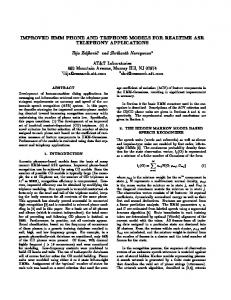
To find the switching radius, we consider the 2D magnetic flux density as shown in Fig. 1(a). For a single wire, B( y ', z ') =
µ0 2π r
( I × er ) where I = Iex and
I = ∫ JdS
.
(3)
S
The total magnetic flux densities at any point (distance vector R) can be calculated by integrating over the current-carrying conductor. For the original ML coil (with inner and outer radii, ai and ao, respectively) B ML ( y , z ) =
µ0 J 2π
∫
/2
− /2
a − ao 1 1 +∫ ∫a − ai R − R ′ i R − R′
dy′dz′eθ
(4a)
where eθ = − sin θ e y + cos θ e z and R − R′ = ( y − y ') 2 + ( z − z ') 2 . Similarly, for a single layer coil, B SL ( y , z ) =
µ0 J ed w / 2 1 1 dz′eθ + 2π ∫− / 2 R − R′+ R − R′−
(4b)
where R − R '± = ( y ∓ ae ) 2 + ( z − z ') 2 . As the magnetic flux is dominant along the centroidal axis, the unknown parameters (Je and ae) are determined to satisfy two conditions: Condition I: Minimize the difference between the two models defined by (5): ∞
E y = ∫ BMz ( y , z ) − BSz ( y, z ) z =
/2
dy
(5)
0
where BMz ( y , z ) = B ML ( y , z )ie z and BSz ( y , z ) = B SL ( y, z )ie z Note that cos θ = ( y − y ′ ) / R − R ′ , we have BMz ( y, / 2) = µ0 J / ( 2π )
(5a)
1 1 + χ i2− 1 + χ i2+ ln + χ i −ϑi − − χ o −ϑo − + χ i +ϑi + − χ o +ϑo + 2 1 + χ o2− 1 + χ o2+
BSz ( y, / 2) Jd = − e w ( cot −1 χ e − + cot −1 χ e + ) µ0 J / ( 2π ) J
(5b)
where χ ± = ( a ± y ) / ; ϑ = cot −1 χ ; and the subscripts i, o, and e denote inner, outer and effective radius respectively. Condition II: The effective current density Je is determined such that BML (0, ± / 2) = BSL (0, ± / 2) (a) Cross sectional view
(b) Magnetic flux on the wire
Fig. 1 Multilayer voice coil
Without loss of generality, we illustrate the modeling method with concentric coils as shown in Fig. 1(a), where some analytical solutions are available for model validation. However, the method can be extended to coils of other customized shape. A. Equivalent Single-layer (ESL) Model Consider a typical multilayer (axi-symmetrical) coil with a current density J, the sectional view of which is shown in Fig. 1(a). The current flowing in the wire towards the +x-axis generates a circular magnetic flux. As a result, the cumulative magnetic fluxes reverse its direction from y=0 to the location ai