ERASURE CORRECTING LDPC CODES FOR CHANNELS WITH PACKET LOSSES Sarah J. Johnson School of Electrical Engineering and Computer Science, The University of Newcastle Callaghan 2308, NSW Australia email:
[email protected]
ABSTRACT In this paper we design low-density parity-check (LDPC) codes for erasure channels with packet losses. Binary base matrices with good minimum stopping set size are designed and superposition is used with these matrices to construct LDPC codes which can correct losses of whole packets. By using superposition, rather than by using the more traditional codeword interleaving, LDPC codes are produced which are much more robust for packet loss channels also corrupted by random erasures. 1. INTRODUCTION A low-density parity-check (LDPC) code is a block code defined by a sparse parity-check matrix, H, and decoded iteratively with message passing decoding. LDPC codes are well known to provide excellent decoding performances on memoryless channels (see e.g. [1]), and recent interest has focussed on their performance on channels with memory [2, 3, 4, 5]. Channels with memory encompass many real-world communications systems including fading environments, packet based communications such as internet transmissions, and magnetic storage devices where the burst errors caused by thermal asperity and media defects are the dominant error type. For memoryless channels the simple binary erasure channel (BEC) has provided a useful framework to understand the performance of LDPC codes (see e.g. [6, 7]), and many of the observations made using the BEC can be usefully applied to more general memoryless channels. Similarly, in this paper we employ binary erasure channels with packet losses as a natural starting point for considering channels with memory. While our motivation in considering a packet loss channel is its simplicity, these erasure channels do occur in some important applications. Dropped packets in Internet transmissions can be modeled as packet losses, and forward error correction is becoming more attractive for these channels, particularly in real time or multicast applications were automatic repeat request schemes are less practical. Similarly, disk failures in disk array systems can be usefully modeled as lost packets. Further, any system where the receiver is able to distinguish deep fades, by employing training sequences for example, can treat the fading period as an erasure burst. In higher order modulation schemes the detection of faded symbols could be modeled as the loss of small binary packets. Here we are considering the design of LDPC codes directly for these channels rather than randomizing the channel This work was supported by the Australian Research Council under Discovery Project Grants DP0449627 and DP00665742.
by interleaving across several codewords. The idea is to design the code for the channel rather than to change the channel to fit the code. In this paper we consider a very simple packet erasure channel and include N p fixed length packets of length L p in each LDPC codeword and introduce Nb packet losses. The remaining received packets can be corrupted by random bit erasures with erasure probability p. A length-n rate-k/n binary error correction code is optimal on the BEC, and called maximum distance separable (MDS), if it can correct any pattern of n − k bit erasures [8]. For the packet loss channel we will say that an error correction code is MDS if it can correct packets of erasures with combined length of up to n − k bits. Although a code may be MDS when decoded with an alternative decoding algorithm, we say that an LDPC code parity-check matrix is MDS-MPA (message passing algorithm) when it can correct any n − k erasures using iterative message passing decoding. The iterative decoding of LDPC codes on erasure channels is particularly straightforward since a transmitted bit is either received correctly or completely erased (it is assumed that the receiver is able to detect an erasure and so deletions are not considered). If only one of the bits in any given code parity-check equation is erased the erased bit can be determined by choosing the value which satisfies the paritycheck equation. Conversely, if more than one bit in any given parity-check equation is erased, no correction can be made using that equation. Message passing iterative decoding of an LDPC code is thus a process of finding parity-check equations which check on only one erased bit. In a decode iteration all such parity-check equations are found and the erased bits corrected. After these bits have been corrected any new parity-check equations checking on only one erased bit are then corrected in the subsequent iteration. The process is repeated until all the erasures are corrected or all the remaining uncorrected parity-check equations check on two or more erased bits. The latter will occur if the erased bits include a set of code bits, S, which are a stopping set [7]: Definition 1 A stopping set, S, is a set of code bits with the property that every parity-check equation which checks on a bit in S checks on at least two bits in S. If all of the bits in a stopping set are erased none of them can be corrected. Thus the stopping set distribution of an LDPC code determines the erasure patterns for which the iterative decoding algorithm will fail on the BEC [7]: Definition 2 An LDPC code parity-check matrix with minimum stopping set size Smin can correct any set of Smin − 1 or fewer erasures using iterative decoding on the BEC. On a burst erasure channel the spacing between the stopping set bits, rather than just the size of the stopping sets,
is the important factor in determining the code performance. Using spacing measures, several authors have considered the burst erasure correcting capability of LDPC codes in the presence of a single erasure burst [3, 4, 5]. In this paper we extend this work to design LDPC codes which can correct multiple erasure bursts in the form of packet losses. The proposed LDPC codes are presented in Section 2 and their performance described in Section 3. 2. LDPC CODES FOR BURST ERASURE CORRECTION A binary LDPC code is represented by a sparse binary paritycheck matrix, H, and a bipartite graph, T , called a Tanner graph. Each bit in the codeword corresponds to a column of H and a bit vertex of T , and each parity-check equation satisfied by the codeword corresponds to a row of H and a check vertex of T . The ( j, i)-th entry of H is ‘1’, and an edge joins the i-th bit vertex and j-th check vertex of T , if the i-th codeword bit is included in the j-th parity-check equation. We design LDPC codes for packet erasure channels by using superposition, starting with a M × N base matrix Hbase , and replacing each non-zero entry in Hbase with v × v permutation matrices, and each zero entry with the v × v all zeros matrix, to create an m × n LDPC code parity-check matrix Hperms where m = Mv and n = Nv. The minimum stopping set size of the base matrix determines the packet erasure correction capability of the final code and the choice of permutation matrices determines its resilience to random erasures in the received packets. We explicitly design base matrices in Section 2.1 before considering the permutation matrices for the superposition in Section 2.2. 2.1 Base matrices for LDPC codes The base matrices we require are small binary matrices which have good minimum stopping set size, ideally which are MDS-MPA. From Lemma 1, this is equivalent to requiring base matrices with minimum stopping set size greater than N − K: Lemma 1 A length N rate K/N LDPC code parity-check matrix which is MDS-MPA will have Smin > N − K. Proof: Follows by definition. An MDS-MPA code must be able to correct any pattern of N − K erasures, however message passing decoding of an LDPC code will fail on a erasure of size Smin and the proof follows. Base matrices with Smin = 2 are straightforward since any stopping set requires two columns. We will use the matrices · ¸ 1 0 1 1 ... 1 Hbase = (1) 0 1 1 1 ... 1 in particular. For a base matrix with Smin = 2 which is MDSMPA we use only one parity-check equation and vary the number of columns to vary the rate: Hbase = [ 1 1
1
... 1 ].
(2)
MDS-MPA base matrices with Smin > 2 are possible by using the parity-check matrix of repetition codes. Length-N, rate1/N, LDPC code parity-check matrices are constructed with
one weight N − 1 column, N N − 1 rows: 1 1 1 0 1 0 Hbase = . .. 0 1 0
columns of weight-1, and M = 0 1 0
0 0 1
0 0 0 0
0 0 0 .. . 0
0 0 0 . 0 1
(3)
Note that not all parity-check matrices of MDS error correction codes will provide MDS-MPA LDPC codes. For example the extended Hamming code # " 1 1 0 0 H= 1 0 1 0 , 1 1 1 1 is not MDS-MPA as it contains a stopping set of size 3. However, the parity-check matrices as defined in (3) are MDSMPA as LDPC codes: Lemma 2 The LDPC codes described by parity-check matrices in the form of (3) are MDS-MPA when decoded with message passing decoding. Proof: Firstly, the weight-1 columns do not overlap and so any stopping set, S, will require the weight-M column. However, all M of the weight-1 columns are then required for S to ensure that every parity-check equation checks on two bits in S. Thus Smin = N and any so N − 1 erased bits can be corrected. Thus we have optimal base matrices for either high rate codes which correct one burst, or low rate codes which correct multiple bursts. Unfortunately, however, binary MDS codes with M > 1 and rate > 1/2 do not exist [9]. For higher rate LDPC codes which correct multiple bursts our strategy is to construct base matrices with maximum possible Smin . Firstly, a stopping set of size two can only occur if there are two identical columns in the code parity-check matrix. Thus we can construct base matrices with Smin = 3 by constructing Hbase with every possible column of every weight, i.e. by using the parity-check matrices of Hamming codes. To design base matrices with Smin ≥ 4 we consider matrices which are systematic, with an M × M identity matrix forming the last M columns. As we have every weight-1 column once in Hbase (in the last M columns) the remaining K columns must be weight Smin − 1 or greater to achieve a minimum stopping set size of Smin . Base matrices for LDPC codes with column weight γ are constructed by: Hbase = [Hγ , I],
(4)
where Hγ has columns of weight γ and is also 4-cycle free and I is an M × M identity matrix. A matrix, H, is 4-cycle free if no two columns of H contain non zero entries in the same two rows. Lemma 3 The matrix Hbase = [Hγ , I] has Smin = γ + 1 if Hγ is 4-cycle free. Proof: Firstly, the weight-1 columns do not overlap and so any stopping set S will require at least one weight-γ column. No other column in Hbase can be incident in more than one row in common with this weight-γ column since
this requires a 4-cycle, which, by definition, is not allowed in Hγ . The remaining columns of Hbase are weight-1 and so also cannot be incident in more than one row in common with this weight-γ column. Thus at least γ more columns are required for S to ensure that every parity-check equation which is incident on the bit corresponding to the weight-γ column is incident on two bits in S and we have Smin ≥ γ + 1. The minimum stopping set size is equal to γ + 1, since every column of Hγ is in a stopping set with the γ weight-1 columns incident on the same rows as it. Avoiding 4-cycles the in the Tanner graphs of LDPC codes can improve the decoding performance of iterative decoding and consequently LDPC matrices which are free of 4-cycles are very well studied with many useful constructions available (see e.g. [10], [11], [12], [13]). However, requiring 4-cycle free codes is a tighter constraint than is actually needed, and we can produce higher rate base matrices by allowing 4-cycles which do not add small stopping sets. For example, we can construct three burst erasure correcting codes by choosing a H3 with Smin ≥ 4. Lemma 4 The matrix Hbase = [H3 , I] has Smin = 4 if H3 has Smin ≥ 4. Proof: Firstly the weight-1 columns do not overlap and so any stopping set S will require at least one of the weight3 columns. If exactly one weight-3 column is included in S then S must be size four since three weight-1 columns are required to ensure that each of the three checks on the bit corresponding to the weight-3 column check on two bits in S. If exactly two weight-3 columns are included in a stopping set, it again must be size at least four since two weight-3 columns can overlap in at most two rows without forming a size two stopping set in H3 , leaving two parity-check equations checking on one bit in S and thus requiring two weight1 columns to complete S. If exactly three weight-3 columns are included in S, it again must be size at least four unless the stopping set is within H3 , violating our requirement that H3 has Smin ≥ 4. Thus any stopping sets of size less than four in Hbase is avoided by our constraint that H3 has Smin ≥ 4 while stopping sets of size four are guaranteed by the inclusion of every possible weight-1 column in Hbase . For example, the base matrix 1 0 0 1 1 1 0 0 0 0 1 1 0 0 1 0 1 0 0 0 Hbase = 1 1 1 0 0 0 0 1 0 0 (5) 0 1 1 1 0 0 0 0 1 0 0 0 1 1 1 0 0 0 0 1 has a minimum stopping set size of 4. Lastly, for a memoryless channel and regular LDPC codes it has been shown that parity-check matrices with columns of weight three are generally the best choice [1]. Thus we consider LDPC base matrices of weight three in our final construction. We propose to use the incidence matrices of 2-(p, 3, 2) designs [14] to form Hbase with Smin ≥ γ + 1. The 2-(p, 3, 2) designs have binary incidence matrices, N, with column weight 3 and every pair of rows of N are incident in two columns of N. The incidence matrices of designs from isomorphism classes without the configurations that lead to small stopping sets are used for Hbase .
2.2 LDPC codes constructed using superposition For a packet loss channel with packets of length L p LDPC codes are designed using superposition with size v = L p permutation matrices so that one packet corresponds to the columns in Hperms from one column of Hbase . Lemma 5 If Hbase has minimum stopping set size Smin then Hperms can be used to correct any Smin − 1 packet losses of size L p = v, if the remaining packets are erasure free. Proof: Since Hbase has a minimum stopping set size of Smin , and since each bit of the stopping set is in a different column of permutations in Hperms , we need to erase Smin packets to erase a stopping set. The case where every non-zero entry in Hbase is replaced with the same permutation matrix is equivalent to independently encoding v codewords using Hbase and then interleaving them. Interleaving codewords in this way is commonly used in bursty channels. However, for LDPC codes the resulting code is not very powerful since each copy of Hbase is a disjoint subgraph in the Tanner graph. By instead choosing different permutation matrices for some of the substitutions we can achieve much more powerful LDPC codes for channels which include random erasures while still providing equivalent packet erasure protection. Choosing different permutation matrices for some of the non-zero entries in Hbase will produce a connected Tanner graph resulting in LDPC codes more resilient to random erasures while still satisfying Lemma 5. Where the base matrices are systematic replacing the entries in the weight-1 columns of Hbase with the identity matrix will ensure a systematic Hperms which is easily encoded via back-substitution. Since the choice of base matrix fixes the packet erasure correction, we also have the flexibility to choose the permutation matrices to improve the code’s resilience to random erasures in the received packets. In particular, permutations for the non-zero entries in the columns of Hbase with weight greater than one can be chosen so as to avoid small cycles in Hperms . When the base matrix is not systematic circulant permutation matrices can be used for the superposition to ensure quasi-cyclic codes and thus ease of encoding (as in [15]). We denote by I i the cyclic shift by i columns left of the identity matrix I. A 4-cycle free Hperms can be constructed by choosing the values of i for each circulant so that the difference in shift values between the two entries of the 4-cycle in one column of Hbase is not the same as the difference in shift values chosen for the two entries of the 4-cycle in the other column of Hbase . Further, by using circulant permutations and swapping columns between packets we can design codes which can correct more packets than is guaranteed by Lemma 5. For example, using the base matrices from (1) the non zero entries in the first row and first two columns are replaced by the v × v identity matrix I and the second non-zero entry in the j-th column, for j > 2, is replaced by the v × v matrix I j−2 . Then the last j − 2 columns in the j-th circulant of Hperms , for j > 2, are swaped with columns from the first two circulants which share a common non-zero entry. The resulting codes are then able to correct up to Smin packet losses using message passing decoding.
0
3. SIMULATION RESULTS
10
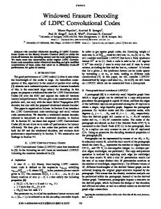
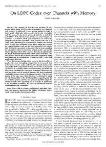
Figs. 1 to 4, show the performance of LDPC codes on packet loss channels with N p = N packets per codeword. Codes of rate-1/5, rate-1/4, rate-1/2, rate-2/3 and rate-5/6 are simulated. The rate-1/5, Np = 5 and rate-1/4, Np = 4 burst error correcting codes (shown in Figs. 1 and 2) are from the MDS-MPA base matrices in (3) and are guaranteed to correct Np −1 lost packets if the remainder are erasure free. The rate5/6, Np = 30 codes use a Hamming code as the base matrix and so are guaranteed to correct at least two lost packets if the remainder are erasure free. The rate-1/2, N p = 14 codes (shown in Figs. 1 and 2) use a 2-(7, 3, 2) design for the base matrix while the rate-1/2, N p = 10 codes (shown in Fig. 2) use the base matrix from (5) and so both are guaranteed to correct at least three lost packets if the remainder are erasure free. Finally, the rate-2/3, N p = 6 codes (shown in Fig. 4), and the rate-1/2, N p = 4 codes (shown in Fig. 3), use the base matrices given in (1). Three different burst error correcting codes are constructed from these base matrices, the first is traditional interleaving (by using identity matrices for the superposition), the second uses superposition with permutation matrices chosen to avoid small cycles and the third uses circulant matrices for the superposition combined with column swaps to increase the packet loss protection. Also shown in Figs. 1 to 4 is the performance of pseudorandomly constructed LDPC codes with the same rate and length, but with all columns weight 3, and constructed to avoid small cycles using the method from [16]. To choose a particular code the average monte-carlo performance of the ensemble has been found by pseudo-randomly generating a new parity-check matrix for each codeword transmitted. Then, by trial and error, using pseudo-randomly constructed codes and simulation, a particular parity-check matrix has been found which performs better than this average. It is this parity-check matrix which is used to simulate the pseudorandom performance in the figures. The maximum number of decoder iterations for all of the codes is set to the number of code parity-check equations. Figs. 1 and 2, show the performance of LDPC codes on noisy packet loss channels with N p = N packets per codeword and a fixed number of small, length L p = 10, packets lost. In every case the LDPC codes formed from the base matrices in Section 2 using superposition produce significantly better performances than the pseudo-random LDPC codes. The codes formed using permutation matrices for the superposition produce significantly better performances than the codes formed using identity matrices for the superposition in all but the MDS-MPA codes where they perform equivalently. Further, the codes constructed using superposition offer guaranteed burst erasure correction performance in a purely packet loss channel and have the advantage of straightforward encoding implementation, advantages not shared by the pseudo-randomly constructed LDPC codes. Figs. 3 and 4, show the performance of LDPC codes on packet loss channels with N p = N, length L p = 100, packets per codeword and a random packet loss probability. The LDPC codes formed using superposition outperform traditional pseudo-randomly constructed LDPC codes, with the codes formed using cyclic permutations for the superposition giving the best performances. The codes constructed using cyclic permutations offer a guaranteed packet correction performance and have the advantage of a straightfor-
10
−1
−2
10
−3
Bit Erasure Rate
10
−4
10
−5
10
−6
10
−7
10
rate−1/4 lngth−4pkts −8
10
rate−1/2 lngth−14pkts rate−5/6 lngth−30pkts
−9
10
−4
10
−3
−2
10 10 Erasure Probability in the Received Packets
−1
10
Figure 1: The performance of LDPC codes on a packet loss channel with 2 packets lost per codeword and varying random erasure rate in the received packets. Dashed curves show LDPC codes formed using superposition with an identity matrix, solid curves show LDPC codes formed using superposition with permutation matrices and dotted curves show the performance of column weight-3 regular LDPC codes with 4-cycles removed.
0
10
−2
10
−4
Bit Erasure Rate
10
−6
10
−8
10
rate−1/5 lngth−5pkts rate−1/2 lngth−10pkts
−10
10
rate−1/2 lngth−14pkts −4
10
−3
−2
10 10 Erasure Probability in the Received Packets
−1
10
Figure 2: The performance of LDPC codes on a packet loss channel with 3 packets lost per codeword and varying random erasure rate in the received packets. Dashed curves show superposition using an identity matrix, solid curves show superposition using permutation matrices and dotted curves show the performance of column weight-3 regular LDPC codes with 4-cycles removed.
ward quasi-cyclic encoding implementation, with only minimal additional complexity for the column swaps between packets.
0
REFERENCES
10
−1
10
−2
Packet Erasure Rate
10
−3
10
−4
10
psuedo−random H H
with identity matrices
H
with permutation matrices
base
−5
10
base
Hbase with circulant matrices −6
10
−2
−1
10
10 Packet Loss Probability
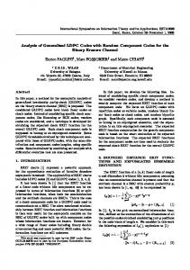
Figure 3: The performance of rate-1/2 LDPC codes with Np = 4 packets per codeword on a packet loss channel with varying packet loss probability. 0
10
−1
Packet Erasure Rate
10
−2
10
−3
10
psuedo−random H
−4
10
H
base
with identity matrices
Hbase with permutation matrices Hbase with circulant matrices
−5
10
−2
−1
10
10 Packet Loss Probability
Figure 4: The performance of rate-2/3 LDPC codes with Np = 6 packets per codeword on a packet loss channel with varying packet loss probability.
4. CONCLUSION In this paper we have designed LDPC codes for packet loss channels using superposition on carefully designed base matrices. The very simple implementation of message passing decoding, and the ease of encoding provided by the structured codes, suggests that LDPC codes constructed in this way represent a promising candidate for applications which suffer from both random and packet losses and face low complexity or high throughput constraints. Future work will extend the code designs considered here to more complex channels with error bursts.
[1] D. J. C. MacKay, “Good error-correcting codes based on very sparse matrices,” IEEE Trans. Inform. Theory, vol. 45, no. 2, pp. 399–431, March 1999. [2] M. Yang and W. E. Ryan, “Design of LDPC codes for two-state fading channel models,” in 5th Int. Symp. Wireless Personal Multimedia Communications, October 2002, pp. 193–197. [3] ——, “Performance of efficiently encodable lowdensity parity-check codes in noise bursts on the EPR4 channel,” IEEE Trans. Magn., vol. 40, no. 2, pp. 507– 512, March 2004. [4] H. Song and J. R. Cruz, “Reduced-complexity decoding of Q-ary LDPC codes for magnetic recording,” IEEE Trans. Magn., vol. 39, no. 2, pp. 1081–1087, March 2003. [5] S. J. Johnson and T. R. Pollock, “LDPC codes for the classic bursty channel,” in International Symposium of Information Theory and its Applications (ISITA’04), Parma, Italy, October 2004, pp. 184–189. [6] M. G. Luby, M. Mitzenmacher, M. A. Shokrollahi, and D. A. Spielman, “Improved low-density parity-check codes using irregular graphs,” IEEE Trans. Inform. Theory, vol. 47, no. 2, pp. 585–598, February 2001. [7] C. Di, D. Proietti, I. E. Telatar, T. J. Richardson, and R. L. Urbanke, “Finite-length analysis of low-density parity-check codes on the binary erasure channel,” IEEE Trans. Inform. Theory, vol. 48, no. 6, pp. 1570– 1579, June 2002. [8] F. J. MacWilliams and N. J. A. Sloane, The Theory of Error-Correcting Codes. Amsterdam: North-Holland, 1977. [9] W. C. Huffman and V. Pless, Fundamentals of ErrorCorrecting Codes. Cambridge University Press, 2003. [10] R. Lucas, M. P. C. Fossorier, Y. Kou, and S. Lin, “Iterative decoding of one-step majority logic decodable codes based on belief propagation,” IEEE Trans. Commun., vol. 48, no. 6, pp. 931–937, June 2000. [11] Y. Kou, S. Lin, and M. P. C. Fossorier, “Low-density parity-check codes based on finite geometries: A rediscovery and new results,” IEEE Trans. Inform. Theory, vol. 47, no. 7, pp. 2711–2736, November 2001. [12] S. J. Johnson and S. R. Weller, “Resolvable 2-designs for regular low-density parity-check codes,” IEEE Trans. Commun., vol. 51, no. 9, pp. 1413–1419, September 2003. [13] ——, “Codes for iterative decoding from partial geometries,” IEEE Trans. Comms, vol. 52, no. 2, pp. 236–243, February 2004. [14] C. J. Colbourn and J. Dinitz (Eds.), The CRC Handbook of Combinatorial Designs. Boca Raton: CRC Press, 1996. [15] Z. Li, L. Chen, L. Zeng, S. Lin, and W. Fong, “Efficient encoding of quasi-cyclic low-density parity-check codes,” IEEE Trans. Commun., vol. 53, no. 11, pp. 1973–1973, November 2005. [16] R. M. Neal, hwww.cs.toronto.edu/radford/homepage.htmli.