Available online at www.sciencedirect.com Available online at www.sciencedirect.com
Procedia Engineering
ProcediaProcedia Engineering 00 (2011) Engineering 29 000–000 (2012) 1142 – 1149 www.elsevier.com/locate/procedia
2012 International Workshop on Information and Electronics Engineering (IWIEE)
Error Feedback Controller for Autonomous Space Teleoperation HU Tianjiana*, HUANG Xuexianga, TAN Qiana, HUANG Jianyua a
Beijing Institute of Tracking and Telecommunications Technology, Beijing, 100094, P.R. China
Abstract As autonomous teleoperation control becomes the new hotspot for space teleoperation, interesting control challenges including large variant timedelay, model error and various disturbances are presented. Facing these practical challenges, the traditional model predictor fails to give a satisfactory solution. In order to make up this limitation, this work designs two kinds of error feedback controller: a linear classical one using error proportional-integral-derivative (PID) and a nonlinear one named active disturbance rejection controller (ADRC). These two approaches are compared via simulations, and higher efficiency of ADRC with new kind of differentiator and state observer added is proven by several simulation results.
© 2011 Published by Elsevier Ltd. Selection and/or peer-review under responsibility of Harbin University of Science and Technology Open access under CC BY-NC-ND license. Keywords: Timedelay; Space Teleoperation; Error Feedback; PID; ADRC
1.Introduction High capability of working in an unknown environment autonomously is a new trend of space teleoperation. In order to fit this new trend, the teleoperation controller should ensure operating stability under large timedelay, and improve tracking performance and capability of disturbance rejection. As shown by literatures [1]-[2], control design of space teleoperation is now a very challenging field of research. This paper proposes two error feedback control techniques for autonomous teleoperation. The first one is a classical kind of linear control technique, proportional-integral-derivative (PID) controller,
* Corresponding author. Tel.: +86-10-6636-1262; fax: +86-10-6636-1034. E-mail address:
[email protected].
1877-7058 © 2011 Published by Elsevier Ltd. Open access under CC BY-NC-ND license. doi:10.1016/j.proeng.2012.01.102
1143
HUAuthor Tianjian et al./ Procedia / ProcediaEngineering Engineering0029(2011) (2012)000–000 1142 – 1149 name
2
and the second robust one is a nonlinear kind, active disturbance rejection controller (ADRC), using arranging transient dynamics, smith predictor and nonlinear extended state observer. In section II, a model of a single DOF telemanipulator is represented, and the limitation of the modelbased predictor method is shown by an example simulation. In section III, two kinds of error feedback controller: PID and ADRC is designed for space teleoperation, and some brief stability analyses for both controllers have been given following method presented by [3]-[6] in section IV. In order to prove the efficiency of the control designs, some simulations have been conducted in Matlab language, and results are presented and analyzed in section V. Conclusions are drawn in section VI. 2.Problem Formulation This section presents the model of the telerobot with timedelay. To put our emphases on the control design, in this work we choose a single DOF telerobot outside gravity field as the object studied. Then the Laplace Transform of the telerobot is obtained: 1C K = s ( Js C + 1) s (Ts + 1)
= G(s)
(1)
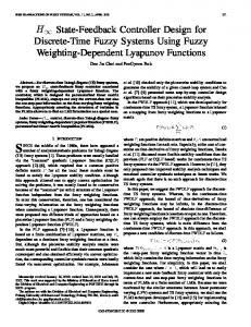
with manipulator inertia J, the damp coefficient C, and naturalization coefficient K & T (this paper supposes K=20, T=0.02). In traditional space teleoperation with operator, error feedback controller is mainly built in the human brain of the operator in most situations. However, due to the lack of operator’s direct participation, limitations of model predictor rise up then. Suppose telerobot is controlled by model predictor alone. Since model error unavoidably exists in any mathematical model, and this error sometimes even grows incredibly in practical situation, the joint angle will absolutely not copy the uplink command just with uplink timedelay, and output error will not decrease with model predictor controlled alone, shown as Fig. 1. Although in computer program, error feedback controller is still a necessary and significant part of autonomous space teleoperation and an introduction to the control design is given subsequently.
1
转角(rad)
0.8
0.6
0.4
0.2
0
0
2
4
6
8
时间( s)
Fig. 1. Joint angle with model predictor alone
3.Error Feedback Controller Design 3.1.Optimal PID controller
10
12
1144
HU Tianjian et al. / Procedia Engineering 29 000–000 (2012) 1142 – 1149 Author name / Procedia Engineering 00 (2011)
3
The proportional-integral-derivative (PID) controller has already been successfully applied in bilateral teleoperation in ETS-VII, and its application in autonomous teleoperation is presented as follows. The PID controller can be written as: C f ( s ) =K p + K i s + K d s
(2)
where weight factorsKp, Ki and Kd are the key to the PID controller design. As the timedelay exp( −τ s ) owns infinite poles and zeros, a new synthesis method based on Generic Algorithms is proposed, shown as Fig. 2. Details of the Generic Algorithms application in controller design can be found in [7]-[8], here we only give a brief explanation to two special parts in our teleoperation control design: z Weight Factor Stable Region Shown in formula (12), the timedelay system owns a special PID weight factor stable region, which gives the range for Gene Encoding. As a close region it is, the weight factor stable region permits that any continuous function will reach both maximum and minimum when independent variables change in the region. That permits an optimal value for the Fitness Function if only it’s continuous. z Fitness Function The optimization of PID weight factors is a multi-object problem, and an integral time absolute error (ITAE) criterion is proposed: ∞
J=
∫τ ( w
1
e(t ) + w2u 2 (t ) + w4 e(t ) ) dt + w3tu
(3)
where e(t ) is the feedback error, u (t ) is the control, tu is the rising time and wi(i=1,2,3,4) is the corresponding weight parameters. Here we suppose w4=0 when e(t ) > 0 as well as w4>>w1 when e(t ) < 0 so that overshoot will be punished by the fitness function. Besides, for timedelay system, the integral should begin from time τ (RTT) but time 0. Other relative parameters are set as: Initial population: 50 and binary encoding. Active crossover probability: [0.5, 0.9]. Active mutation probability: [0.005, 0.05]. Fitness weight parameters: w1=1, w2=0.001, w3=20, w4=200. and optimization results can be seen in Table 1 as RTT changes.
Fig. 2. PID weight factors optimization process
3.2.Active Disturbance Rejection Control(ADRC) First presented in Han [4], a nonlinear error feedback controller, Active Disturbance Rejection Controller (ADRC) is proposed using Tracking-Differentiator (TD) to arrange system transient dynamics
1145
HUAuthor Tianjian et al./ Procedia / ProcediaEngineering Engineering0029(2011) (2012)000–000 1142 – 1149 name
4
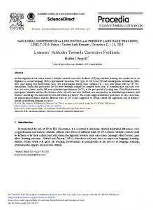
and Extended State Observer (ESO) to feedback estimated disturbances. For teleoperation system with timedelay, a Smith Predictor which is a unique part from most situations is built into tradition ADRC framework so that when controller designed, the teleoperation system could be treated as a plant without timedelay. Besides, uncertainties such as model error, random city of timedelay and so on are considered as unknown disturbances estimated by ESO and fed back to compensate the control actively. The framework of ADRC for space teleoperation is shown in Fig. 3. First, the state space of teleoperation system shown as equation (1) is derived as: ⎧ X& (= t ) AX (t ) + Bu (t − τ ) + Dw(t ) ⎨ Y (t ) = LX (t ) ⎩
(4)
with state variable X=[x1,x2]T=[ θ , θ& ]T, control torque u= τ c, disturbance torque w= τ d, output y=x1= θ and matrix A=[0,1;0,-C/J],B=[0,1]T,D=[0,1]T and L=[1,0]T.And then the Tracking-Differentiator (TD) for discrete signal is given as:
⎧ fh = fhan( x1 ( k ), x2 ( k ), r , h) ⎪ = x1 (k ) + hx2 ( k ) ⎨ x1 (k + 1) ⎪ x (k += 1) x2 (k ) + h ⋅ fh ⎩ 2
(5)
where fhan(x1,x2,r,h) is
⎧ d= rh2, a0 = hx2, y = x1 +a0, a1 =d ( d +8 y ) ⎪ ⎪ a2 = a0 +sign(y)(a1 −d) 2 ⎪⎪ = fsg ( y , d ) (sign(y +d) −sign(y −d)) 2 ⎨ ⎪ a =(a0 + y) fsg(y, d) +a2(1− fsg(y, d)) ⎪ ⎪ fhan =−r(a) fsg(a, d) −r ⋅ sign(a)(1− fsg(a, d)) ⎪⎩ d
(6)
The Extended State Observer (ESO) is designed as: z1 − y0, fe = fal(e,0.5, h), fe1 = fal(e,0.25, h) ⎧e = ⎪ z1(k +1)= z1(k) +h(z2(k) −β01e) ⎪ ⎨ + ( z k ⎪ 2 1)= z2(k) +h(z3(k) −β02 ⋅ fe +u(k)) ⎪⎩ z3(k +1)= z3(k) +h(−β03 ⋅ fe1)
(7)
in which fal (e, λ , h) is
⎧⎪ e λ sign(e) fal (e, λ , h) = ⎨ −λ ⎪⎩ e ⋅ h
e >h e ≤h
(8)
And the Smith Predictor is realized using TD: = ⎧ f y fhan ( y1 ( k ) − y ( k ), y2 ( k ), r1 , h ) ⎪ y1 ( k + 1) = y1 ( k ) + hy 2 ( k ) ⎪ ⎨ y ( k 1) y 2 ( k ) + h ⋅ f y + = 2 ⎪ ⎪⎩ y= y1 ( k ) + α y y2 ( k ) 0 (k )
(9)
1146
HU Tianjian et al. / Procedia Engineering 29 000–000 (2012) 1142 – 1149 Author name / Procedia Engineering 00 (2011)
v1
v
v2
+ −
e1
u0 −
+ − e2
+
u
Ke −τ us s (Ts + 1)
1 b0
z2 z1
w
y
e −τ ds
b0 z3
+
5
y1
u y0
Fig. 3. ADRC for space teleoperation
4.Stability Analysis
In this section, the stability of the two above controllers is discussed by the proper polynomial theory presented in Li [3] and t Self Stable Region (SSR) theory and Lyapunov method [6]. 4.1.Stable region for PID controller Referred to formula (1), we can get the close-loop transfer function and proper polynomial of the system:
Gcl ( s ) =
C f ( s )G ( s ) exp(−τ u s )
(10)
1 + C f ( s )G ( s ) exp( −τ s )
(
)
Λ ( s ) = Ts 3 + s 2 + K K d s 2 + K p s + K i exp( −τ s )
(11)
Substituting with Euler’s formula exp( −iτω= ) cos(τω ) − i sin(τω ) into formula (11), the boundary of the stable region can be obtained when proper polynomial Λ (iω ) = 0 : = Kp Ki = Kd =
ω
( sin(τω ) + T ω cos(τω ) ) K nω 2 ( cos(τω ) − T ω sin (τω ) )
(12)
K (n −ω2 )
ω 2 ( cos(τω ) − T ω sin (τω ) ) K (n − ω2 )
with additive formula Ki=nKd. Planes Ki=0, Kd=0as well as the formula (12) together determine a 3D stable region, which is a combination of two crossed columns. That’s the stable region for PID controller of teleoperation. The significance for the stable region is not only the guarantee to the control stability, but also a limited range for Generic Encoding, as presented in section III. 4.2.Stability analysis on ADRC
1147
HUAuthor Tianjian et al./ Procedia / ProcediaEngineering Engineering0029(2011) (2012)000–000 1142 – 1149 name
6
In Huang & Han [6], the stability of a second order ESO has been proven applying Self Stable Region (SSR) theory and Lyapunov function method. Though the stable problem of ADRC containing a third order ESO should be solved here, similar method could be adopted after a few transforms. First a formula related to estimated error state z3 is derived from formula (7) when parameter β 03=1/3h:
z3 (k + 1) − z3 (k ) =fe1 3
(13)
And it is obvious that z3 will vanish as e finally since the derivative of z3 seizes opposite sign to error e , and then a second order state error formula can be derived from formulas (7) and (9):
ε 2 − β 01ε1 ⎧ ε&= 1 ⎨& − β 02 ⋅ fe − f y ⎩ε 2 =
(14)
where ε 1=z1-y1, ε 2=z2-y2. Given an arbitrary continuous positive function g1(e1) and a constant k, where g1(0)=0 and k>1, the following formula (15) will lead to the Self Stable Region which is shown as formula (16) for the formula (14).
h2 (e1 , e2 ) = e2 − β 01e1 + kg1 (e1 ) sign(e1 )
(15)
{(e , e ) | h (e , e ) ≤ g (e )}
(16)
= G2
1
2
2
1
2
1
1
The Self Stable Region G2 means once stayed in it, the system locus would asymptotically converge to zero. This can be proved in Lyapunov method with a Lyapunov function V1=0.5e1^2. And all system loci across the region outside G2 will come into G2 in infinite time and stay in it forever if only β 01^2> β 02* h-0.5 with a Lyapunov function V2=0.5(h2(e1,e2)^2-g1(e1)^2) as its proof. 5. Simulation Results
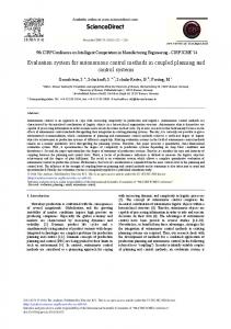
In this section, some simulations are conducted in Matlab language to illustrate the performance and robustness of proposed control laws including PID and ADRC to autonomous space teleoperation with different timedelay, model error and various disturbances. Simulation conditions are: z Teleoperation System shown as Fig. 1 and formula (1) is considered with K=20, T=0.02. z Expected Joint Angle i.e. Input: 1 rad, Control Frequency: 100Hz. z Optimal PID Weight Factors for different Round Trip Timedelay(RTT). z Parameters of ADRC r0=1,r1=1,r=3,h=0.01, α y=0.05, β 01=1/3h, β 03=3 β 02, β 1= β 2=70,b0=7380. And system step response is shown in Fig. 5. Obviously, steady-state error is eliminated once state error is fed back, and anxiety on model predictor doesn’t exist any longer. In Fig. 4(a) and (b), the basic performance of PID and ADRC with different RTT is obtained and summarized in Table. 2. Though better in tracking velocity, the PID controller seems much weaker in control stability, compared to ADRC. Robustness is studied in Fig. 5(a), (b) and (c), in which 20% model error is added, and system stability is assured by both of PID and ADRC. However, tracking performance is kept much better by ADRC. And in Fig. 5(d), a good capability of disturbance rejection is shown, when two kinds for disturbance torque (w=0.1Nm, w=0.1sign (sin (t))Nm) and random RTT, which follows the Gauss distribution with the mean of 6s and the variance of 0.3s^2, is considered.
1148
HU Tianjian et al. / Procedia Engineering 29 000–000 (2012) 1142 – 1149 Author name / Procedia Engineering 00 (2011)
7
1
Joint Angle(rad)
0.8
0.6
0.4
0.2
0
0
5
10
15 Time( sec)
20
25
30
Fig. 4. (a) Step response with PID controller; (b) Step response with ADRC
T 20% K 20%
1
K 20%
K ,T unchanged 0.8
T 20%
Joint Angle( rad)
K 20%
T 20%
K 20%
0.6
T 20%
0.4
K ,T unchanged
0.2
0
0
5
10
15
20
25
Time(s)
T 20%
K ,T unchanged
K 20% 1
T 20%
Joint Angle(rad)
0.8
K 20%
0.6
0.4
0.2
0
0
5
10
15 Time(s)
20
25
Fig. 5. (a) Step response with model error(PID, RTT=2s); (b) Step response with model error(ADRC, RTT=6s); (c) Step response with model error(PID, RTT=6s); (d) Step response with disturbances(ADRC, RTT=6s)
30
1149
HUAuthor Tianjian et al./ Procedia / ProcediaEngineering Engineering0029(2011) (2012)000–000 1142 – 1149 name
8
Table 1. Optimal PID weight factors for different timedelay Optimal PID weight factors
RTT(sec) Kp
Ki
Kd
2
0.2293
0.8323
0.0350
6
0.1382
0.4394
0.0117
8
0.1736
0.1153
0.0275
Table 2. Performance of PID and ADRC Optimal PID
RTT(sec)
ADRC
Rising time(sec)
Peak time(sec)
Percent overshoot(%)
Settling time*(sec)
Rising time(sec)
Peak time(sec)
Percent overshoot(%)
Settling time*(sec)
2
15
15
0
9.5
28
28
0
12.5
6
5.9
8
20
11
18
18
0
17.5
8
6
9
58
57
9.5
12
10
16.5
*Settling time: the time for
±5%
error of desired angle
6. Conclusions
We presented here two kinds of error feedback controller for autonomous space teleoperation. Though weaker in tracking velocity, ADRC seems a better stability, robustness and capability of disturbance rejection to PID as simulation results show. And it’s quite reasonable for higher efficiency of ADRC due to its inherent nonlinear structure including Transient Dynamics Arrangement which sets the desired input trajectory changing gradually and ESO which feeds estimated error back to compensate the control torque actively. Therefore, in most situations ADRC seems a better choice, and ground experimental results are expected in the coming months using ADRC on a 3DOF manipulator. References [1] Thomas B.Sheridan. Space Teleoperation Through Timedelay: Review and Prognosis. IEEE Trans. On Robotics And Automation, VOL. 9. NO. 5. October 1993;592-606. [2]CHEN Junjie. A Survey on Control Method of Teleoperation with Timedelay. Measure and Control Technology, 2007 VOL. 26(2); 1-5. [3] Jihong Li, Pingkang Li. Stability Regions Analysis of PID Controllers for Time-delay Systems. Proceedings of the 6th World Congress on Intelligent Control and Automation, June 21-23, 2006, Dalian, China;2219-2223. [4] Han Jingqing. Active Disturbance Rejection Control Technique . Beijing: National Defense Industry Press; 2009. [5] W.Xue, Y.Huang. Stability analysis of ADRC for nonlinear systems with unknown dynamics and disturbance. Theory and Applications of Complex Systems, 2010. [6] Huang Y, Han J Q. Analysis and design for nonlinear continuous extended state observer. Chin. Sci. Bull., 2000; 45: 13731379. [7] Xiangzhong Meng, Baoye Song. Fast Genetic Algorithms Used for PID Parameter Optimization. Proceedings of the IEEE Intl. Conf. on Automation and Logistics. August 18-21, 2007, Jinan, China; 2144-2148. [8] Guohan Lin, Guofan Liu. Tuning PID Controller Using Adaptive Genetic Algorithms. The 5th Intl. Conf. on Computer Science & Education. August 24-27, 2010, Hefei, China; 519-523.