Nov 4, 2013 - which have a relatively simple relation to Kraus opera- ...... Justin Dressel, Andrzej Veitia, Jay Gambetta, Michael. Geller, and John Martinis for ...
Error matrices in quantum process tomography Alexander N. Korotkov
arXiv:1309.6405v2 [quant-ph] 4 Nov 2013
Department of Electrical Engineering, University of California, Riverside, California 92521 (Dated: November 6, 2013) We discuss characterization of experimental quantum gates by the error matrix, which is similar to the standard process matrix χ in the Pauli basis, except the desired unitary operation is factored out, by formally placing it either before or after the error process. The error matrix has only one large element, which is equal to the process fidelity, while other elements are small and indicate imperfections. The imaginary parts of the elements along the left column and/or top row directly indicate the unitary imperfection and can be used to find the needed correction. We discuss a relatively simple way to calculate the error matrix for a composition of quantum gates. Similarly, it is rather straightforward to find the first-order contribution to the error matrix due to the Lindbladform decoherence. We also discuss a way to identify and subtract the tomography procedure errors due to imperfect state preparation and measurement. In appendices we consider several simple examples of the process tomography and also discuss an intuitive physical interpretation of the Lindblad-form decoherence. PACS numbers: 03.65.Wj, 03.65.Yz, 03.67.-a, 85.25.Cp
I.
INTRODUCTION
Quantum process tomography (QPT) [1–9] is a way to completely characterize a quantum process. It is the main tool for experimental characterization of quantum gates, being developed for potential use in a quantum computer. QPT has been realized in numerous experiments, practically in all types of qubit systems, including, e.g., NMR [10, 11], linear optics [6, 12, 13], ion traps [14, 15], and superconducting qubits [16–21]. In this paper we mainly focus on QPT with superconducting qubits, even though our discussion is applicable to other systems as well. Unfortunately, QPT requires resources, which scale exponentially with the number of qubits. For N (superconducting) qubits the number of initial states is usually 4N (or sometimes 6N ), and the number of “measurement directions” (state tomography “rotations”) for each initial state is typically 3N (or 6N ). Each such setup typically requires a few hundred or a few thousand experimental runs. From this scaling it is easy to estimate that the QPT of a 1-qubit or a 2-qubit quantum gate requires a manageable number of experimental runs, while a 3-qubit QPT is rather difficult to realize, and the full QPT with 4 and more qubits seems to be impractical. The problem of exponential scaling of QPT resources with the number of qubits can be mitigated if we do not need full information about a quantum gate operation, but instead need only some information. Thus a partial characterization of a multi-qubit operation is an important area of theoretical research [22–28]. This includes randomized benchmarking [22, 29, 30], which typically provides only one number: the gate fidelity. Randomized benchmarking becomes increasingly preferable for superconducting qubits [31–33]. Another promising way to solve or a least alleviate the problem of exponential scaling is to use a compressed-sensing implementation of QPT [35–37].
One more problem with QPT is its sensitivity to state preparation and measurement errors (SPAM in the terminology of Ref. [31]). Randomized benchmarking does not suffer from SPAM-errors, so this is another reason why this technique is increasingly popular. However, the obvious drawback of randomized benchmarking is that it gives only the total (average) error and does not give any information about particular kinds of error. Hence, it does not tell us about the origin of a quantum gate imperfection. In this paper we consider standard QPT, which gives full information about the quantum process. Because of the scaling problem, we are essentially talking about quantum gates with less than 4 qubits, for which full QPT is a very useful tool. The standard way of representing QPT results is via the process matrix χ [1] in the Pauli basis (see the next section). Unfortunately, this matrix is a rather inconvenient object to work with. Even though in principle it contains full information about the process, it does not show useful information in a straightforward way. Thus the important problem of converting experimental QPT data into a useful characterization of particular decoherence processes [8, 24, 26, 38–40] is not quite simple. Besides the standard matrix χ, there are other ways to represent QPT results. For example, they can be represented via the so-called Pauli transfer matrix R [34]. The advantage of using R is that it contains only real elements, from R it is simple to see whether the quantum operation is trace preserving, also simple to see whether the process is unital, and for any Clifford operation there is exactly one non-zero element in each row and column of R with unit magnitude. In this paper we discuss one more way of representing the experimental QPT results [41]. It is essentially the standard χ-matrix representation in the Pauli basis, with the only difference being that we factor out the desired unitary operation U , so that the error matrix χerr de-
2 scribes only the imperfections of the experimental quantum gate. There are two natural ways to define such an error matrix (χerr and χ ˜err ): we can assume that the U operation is either before of after the error process (see Fig. 1 below). Even though in theoretical analyses it is rather usual to separate the error channel and unitary operation, we are not aware of any detailed discussion of the QPT representation by the error matrices. As discussed in this paper, the error matrix χerr (as well as χ ˜err ) has a number of convenient properties. In particular, its main element is equal to the process fidelity Fχ , while other non-zero elements correspond to imperfections. Unitary imperfections are directly given by the imaginary parts of the elements along the left column and/or top row. Decoherence produces other elements, which have a relatively simple relation to Kraus operators characterizing decoherence (which are the operators in the Lindblad equation). Since the elements of the error matrix are small, most calculations can be approximated to first order, thus making them relatively simple. This includes a relatively simple rule for the composition of quantum operations and accumulation of the errormatrix elements due to the Lindblad-form decoherence. The error-matrix representation has already been used in the experimental QPT [21]. Our paper is organized in the following way. In Sec. II we briefly review some properties of the standard process matrix χ. In Sec. III we introduce the error matrices χerr and χ ˜err , and then in Sec. IV some of their properties are discussed, including physical interpretation. In Sec. V we consider composition of the error processes. Then in Sec. VI we discuss the use of the error matrix to find the necessary unitary correction to an experimental quantum gate. In Sec. VII we consider the contribution to the error matrix from decoherence described by the Lindblad-form master equation. A possible identification of SPAM errors and their subtraction from the error matrix are discussed in Sec. VIII. Finally, Sec. IX is the conclusion. Two appendices discuss topics that are somewhat different from the main text. In Appendix A we consider several simple examples of the χ-matrix calculation, and in Appendix B we discuss an intuitive interpretation of decoherence described by the Lindbladform master equation, unraveling the quantum dynamics into the “jump” and “no jump” scenarios.
II.
STANDARD PROCESS MATRIX χ
A linear quantum operation ρin → ρfin (transforming initial density matrix ρin into the final state ρfin ) is usually described via the process matrix χ (which is Hermitian, with non-negative eigenvalues), defined as [1] X ρfin = χmn Em ρin En† , (1) m,n
where the matrices En form a basis in the space of complex d×d matrices, which are the linear operators in the
d-dimensional Hilbert space of the problem. For example, for N qubits d = 2N ; therefore there are (2N )2 = 4N matrices En , and the matrix χ has dimensions 4N × 4N . (Note that En are operators in the space of wavefunctions, and these operators have the same dimension as density matrices.) Even though in principle any basis {En } (not necessarily orthogonal [42]) can be used in Eq. (1), the most usual choice for a system of qubits is the use of Pauli matrices. In this case for one qubit the basis {En } consists of 4 matrices: I ≡ 11, X ≡ σx , Y ≡ σy , Z ≡ σz ,
(2)
and for several qubits the Kronecker product of these matrices is used; for example for two qubits {En } = {II, IX, IY, IZ, XI, ..., ZZ}. Note that sometimes a different definition for Y is used: Y ≡ −iσy . Also note that the basis of Pauli matrices is orthogonal (under the Hilbert-Schmidt inner product) but not normalized [42], so that † hEm |En i ≡ Tr(Em En ) = δmn d, d = 2N ;
(3)
this is why normalization by d in often needed in the QPT. In this paper we will always assume the Pauli basis {En } and use Y ≡ σy . Therefore En† = En , but for clarity we will still write En† in formulas when appropriate. It is simple to find the matrix χ for a multi-qubit unitary operation U . We firstPneed to find its represention in the Pauli basis, U = n un En , and then compare U ρin U † with Eq. (1), which gives χmn = um u∗n , un =
1 Tr(U En† ), d
(4)
where the star notation means complex conjugation and the expression for un follows from the orthogonality property (3). Calculation of the matrix χ for a quantum process with decoherence is usually significantly more cumbersome. Some examples are considered in Appendix A (see also, e.g., [8]). A process is called “trace-preserving” if the transformation (1) preserves the trace of the density matrix, i.e. if Tr(ρfin ) = 1 when Tr(ρin ) =P 1. In this case the matrix χ should satisfy the condition m,n χmn En† Em = 11 (which gives 4N real equations), and therefore χ is characterized by 16N − 4N real parameters instead of 16N parameters in the general (non-trace-preserving) case. In this paper we always assume a trace-preserving operation. The fidelity of a trace-preserving quantum operation compared with a desired unitary operation is usually defined as Fχ = Tr(χdes χ),
(5)
des
where χ is for the desired unitary operation and χ is for the actual operation (it is easy to show that 0 ≤ Fχ ≤ 1). This definition has direct relation [43, 44] 1 − Fχ = (1 − Fav )
d+1 d
(6)
3 F
=
U
Ferr
=
~ err F
U
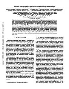
FIG. 1: Quantum circuit diagrams, which define the error processes characterized by error matrices χerr and χ ˜err via their relation to χ and the desired unitary operation U . The time runs from left to right.
to the average state fidelity Fav = Tr(ρfin ρdes fin ), which assumes uniform averaging over all pure initial states. Sometimes [30] Fav is called “gate fidelity” while Fχ is called “process fidelity”. Characterization by Fav is usually used in randomized benchmarking [22, 29–32]; it is easy to see that 1/(d + 1) ≤ Fav ≤ 1. Note that the fidelity definition (5) requires unitary desired operation and trace-preserving actual operation. For a general (non-unitary) desired operation (still assuming trace-preserving operations) it should be replaced with the “Uhlmann fidelity” Fχ =
�
�2 �2 � qp q p √ des √ Tr , χχ χ χdes χ χdes = Tr
(7) which is essentially the same definition as for the fidelity between two density matrices [1].
III.
ERROR MATRICES χerr AND χ ˜err
The process matrix χ for a non-trivial unitary operation typically has many non-zero elements (e.g., 16 elements √ for the two-qubit controlled-Z, controlled-NOT, and iSWAP operations), and it is nice-looking on the standard bar (“cityscape”) chart used for visualization. However, a large number of non-zero elements (we will call them “peaks”) creates a problem in visual comparison between the desired and experimental χ-matrices, especially for high-fidelity experiments. A natural way to make it easier to compare between the actual and desired operations is to show the difference between them, i.e., to show the error. For example, it is possible to calculate and display the difference χ − χdes in the Pauli basis. However, such element-by-element difference does not make much sense mathematically. Instead, let us represent the actual quantum process as a composition of the desired unitary U and the error process (Fig. 1), and find the process matrix χerr for this error operation. This essentially reduces the comparison between χ and desired U (we use a loose language here) to the comparison between χerr and the memory (identity) operation. So, the general idea is to convert the desired unitary U into the memory operation, and this converts χ into the error process matrix χerr . There are two ways of defining such error matrix: we can place the error process either before or after the desired unitary U (Fig. 1). Thus, we define two error matrices: χerr and χ ˜err using the
relations [see Eq. (1)] X † † ρfin = χerr mn Em U ρin U En , m,n X † † ρfin = χ ˜err mn U Em ρin En U . m,n
(8) (9)
From Fig. 1 it is obvious that the process χerr can be represented as the composition of the inverse ideal unitary (U −1 = U † ) and the actual process χ after that. Similarly, χ ˜err is the composition of χ and inverse unitary U † after that. Hence, χerr and χ ˜err represent legitimate quantum processes and therefore they satisfy all the properties of the usual matrix χ (see the previous section); in particular, χerr and χ ˜err are positive Hermitian matrices. We will use the standard Pauli basis for the error matrices χerr and χ ˜err . Using the composition relation, the error matrices can be calculated from χ as [8] † χerr = V χV † , Vmn = Tr(Em En U † )/d, † χ ˜err = V˜ χV˜ † , V˜mn = Tr(Em U † En )/d.
(10) (11)
In an experiment the error process matrices can be calculated either from χ using these equations or by directly applying the definitions (8) and (9) to the experimental data. For example, to find χ ˜err the measured final density matrices can be transformed numerically as ρfin → U † ρfin U and then the usual procedure of χ calculation can be applied. Note that the matrix χerr can be thought of as the χ-matrix in the rotated basis {En U } instead of {En }; similarly, χ ˜err is formally the χ-matrix in the basis {U En }; however, we will not use this language to avoid possible confusion. In the ideal (desired) case both error processes χerr and err χ ˜ are equal to the perfect memory (identity) operation, χerr = χ ˜err = χI , for which χImn = δm0 δn0 ,
(12)
where with index 0 we denote the left column and/or the top row, which correspond to the unity basis element (in the usual notation 0 = I for one qubit, 0 = II for two qubits, etc.); the process matrix (12) is given by Eq. (4) with un = δn0 . So, in the ideal case the error matrices have only one non-zero element at the top left corner: χerr ˜err 00 = χ 00 = 1. Therefore, any other non-zero element err in χ (or χ ˜err ) indicates an imperfection of the quantum operation. This is the main advantage in working with χerr or χ ˜err instead of the usual matrix χ. There are also some other advantages discussed below. The standard process fidelity (5) for a trace-preserving operation has a very simple form for the error matrices. Since χ, χerr , and χ ˜err are essentially the same operator in different bases, we have Tr(χdes χ) = Tr(χI χerr ) = Tr(χI χ ˜err ). Therefore Fχ = χerr ˜err 00 = χ 00 ,
(13)
i.e. the process fidelity is just the height of the main (top left) element of the error matrix χerr or χ ˜err .
4 A systematic unitary error can be easily detected (to first order) in the error matrix χerr or χ ˜err because it appears at a special location: it produces non-zero imaginary elements along the top row and left column of err the matrix, i.e. the elements Im(χerr 0n ) = −Im(χn0 ) with n 6= 0 (similarly for χ ˜err ). To see this fact, let us assume that instead of the desired unitary operation U , the quantum gate actually realizes a slightly imperfect unitary U actual . Then χerr corresponds to the unitary U err = U actual U †P , which can be expanded in the Pauli err err basis as U err = ≈ 11, we have n un En . Since U err err u0 ≈ 1 and |un6=0 | ≪ 1. Note that uerr can al0 ways be chosen real because U err is defined up to an overall phase. Now let us show that to first order all uerr n6=0 are purely imaginary. This follows from the firstorder expansion P of the equation U err U err † = 11, which 2 err err ∗ gives |uerr | 1 1 + )En = 11. Hence, 0 n6=0 (un + un err err ∗ un + un = 0 for n 6= 0 (purely imaginary uerr n6=0 ), and the difference uerr 0 − 1 is only of second order (for a real err uerr 0 ). Another way of showing that in the first order un6=0 err iHerr are imaginary is by using representation U = e (neglecting the overall phase) with aPHermitian matrix Herr , so that the expansion Herr = n herr n En contains err all real coefficients, while to first order uerr n6=0 = ihn6=0 and = 1. uerr 0 Now using Eq. (4) we see that to first order the only non-zero elements (except χerr 00 ) are
we will discuss the general way to calculate the first-order pattern for a particular decoherence mechanism; for a practical quantum gate this pattern may contain many elements. A special role is played by the real elements along the top row and left column of χerr (or χ ˜err ): they correspond to the gradual non-unitary (“Bayesian”) evolution in the absence of the “jumps” due to decoherence (in contrast to the imaginary elements, which correspond to the unitary imperfection) – see discussion later. Note that the diagonal matrix elements of χerr are the error probabilities in the so-called Pauli twirling approximation [22, 45–47]. Therefore these elements can be used in simulation codes, which use the Pauli twirling approximation for the analysis of quantum algorithms in multi-qubit systems. Concluding this section, we emphasize that the error matrix χerr (and/or χ ˜err ) is just a minor modification of the standard χ matrix; they are related by a linear transformation and therefore equivalent to each other. However, in the error matrix only one peak (at the top left corner) corresponds to the desired operation, while other peaks indicate imperfections. This makes the error matrix more convenient to work with, when we analyze deviations of an experimental quantum operation from a desired unitary and try to extract information about the main decoherence mechanisms.
err err Im(χerr n0 ) = −Im(χ0n ) ≈ −iun , n 6= 0.
IV. SOME PROPERTIES OF THE ERROR MATRICES AND INTERPRETATION
(14)
Note that the diagonal elements χerr nn (as well as the change of χerr 00 ) in this case are of second order. In particular, in this approximation Fχ ≈ 1. As discussed later, if decoherence causes a significant decrease of the fidelity Fχ , then a better approximation of the systematic unitary error effect is Eq. (14) multiplied by the fidelity, err Im(χerr n0 ) ≈ −iFχ un .
(15)
Using this equation it is possible to find uerr n from an experimental matrix χerr and therefore estimate the systematic unitary error U err in the experiment. The same property (14) [and its version (15) corrected for Fχ ] can be shown for χ ˜err using the similar deriva˜ err = U † U actual ≈ 11. tion for the unitary imperfection U err The elements Im(χ ˜n0 ) ≈ −iFχ u ˜err n are different compared with the matrix elements of χerr ; they are related ˜ err = U † U err U or equivalent equation via the equation U err † err ˜ − 11 = U (U − 11)U . U Decoherence produces additional small peaks in the error matrix χerr (and/or χ ˜err ). As discussed later, to first order these peaks are linear in the decoherence strength and simply additive for different decoherence mechanisms. Therefore, to first order we have a weighted sum of different patterns in χerr for different mechanisms. If these patterns for the most common decoherence mechanisms are relatively simple, then there is a rather straightforward way of extracting information on decoherence from experimental χerr matrix. In Sec. VII
In this paper we always assume high-fidelity operations, 1 − Fχ ≪ 1,
(16)
so that the first-order approximation of imperfections is quite accurate. Since the error matrix χerr is positive, its off-diagonal elements have the upper bound p err |χerr χerr (17) mn | ≤ mm χnn .
(The same is true for χ ˜err , but for brevity we discuss here err only χ .) Therefore for a high-fidelity operation (16) only the elements in the left column top row can be √ errand p err relatively large, |χerr χnn ≤ 1 − Fχ , while 0n | = |χn0 | ≤ other off-diagonal element have a smaller upper bound, |χerr mn | ≤ (1 − Fχ )/2, because all diagonal elements except χerr 00 are small. Actually, it is possible to show (see below) err that Re(χerr 0n ) are also small, |Re(χ0n )| ≤ (1 − Fχ )/2, so err only Im(χ0n ) can be relatively large. err The elements Im(χerr 0n ) and Im(χn0 ) play a special role because a unitary imperfection produce them in the first order, while other elements are of second order [see Eq. (4) and discussion in the previous section]. It is√easy to err err see that Im(χerr 0n ) and Im(χn0 ) can approach ± χnn if the error is dominated by the unitary imperfection. The physical intuition in analyzing the error of a quantum gate is that the (small) infidelity 1 − Fχ comes from
5 small unitary imperfections and from rare but “strong” decoherence processes, which cause “jumps” that significantly change the state. As discussed later, this picture should also be complemented by small non-unitary state change in the case when no jump occurred (this change is essentially the quantum Bayesian update [48–50] due to the information that there was no jump). It is not easy to formalize this intuition mathematically; however, there is a closely related procedure. Let us diagonalize the error matrix χerr , so that χerr = T DT −1,
(18)
where T is a unitary d2 × d2 matrix and D = diag(λ0 , λ1 , . . . ) is the diagonal matrix containing d2 real eigenvalues of χerr . These eigenvalues are non-negative, and we can always choose T so that in D they are ordered as λ0 ≥ λ1 ≥ · · · ≥ λd2 −1 . The sum of the eigenvalues is equal 1 (since we consider trace-preserving operations) and the largest eigenvalue λ0 is close to 1 because Fχ ≤ λ0 ≤ 1. [Here λ0 ≥ χerr 00 because any diagonal element of a Hermitian matrix should be in between the largest and smallest eigenvalues, as follows from expanding the corresponding basis vector inP the eigenbasis.] All other eigenvalues are small because k>0 λk ≤ 1 − Fχ . The diagonalization (18) directly gives the evolution representation via the Kraus operators [51], ρf in =
2 dX −1
λk Ak (U ρin U † )A†k ,
k=0
Ak =
X
X
λk A†k Ak = 11, (19)
k
a(k) n En ,
a(k) n
= Tnk ,
(20)
n
in which the operators Ak form an orthogonal basis, hAm |An i = δmn d [see Eq. (3)] because T is unitary. Recall that U is the desired unitary gate – see Eq. (8). The main term in the Kraus-operator representation (19) is the term with λ0 ≈ 1; let us show that A0 ≈ 11 (up to an overall phase, which can always be eliminated); this (0) (0) means a0 ≈ 1 and |an | ≪ 1 for n 6= 0 [note that P (0) 2 n |an | = 1 because T is unitary; therefore it is suf(0) ficient to show that a0 ≈ 1]. This can be done in the following way. Since X (k) ∗ χerr λk a(k) (21) mn = m (an ) , k
the fidelity is Fχ =
X
k
(k)
λk |a0 |2 .
(22)
The contribution of the terms with k 6= 0 to the fidelity is at least smaller than 1 − Fχ because this is the bound P (k) for k>0 λk and |a0 | = |T0k | < 1 for a unitary T (this contribution is actually even much smaller, as discussed (0) (0) below). Therefore λ0 |a0 |2 > 2Fχ − 1, and so |a0 |2 > (0) (0) 1 − 2(1 − Fχ ). Choosing real a0 , we obtain a0 ≈ 1, and therefore A0 ≈ E0 = 11.
Since A0 is close to E0 and other Ak are orthog(k) onal to A0 , the components a0 are small for k 6= P (0) (k) (0) (k) 0. Using the relation (a0 )∗ a0 + n>0 (an )∗ an = (k)
0 (since T is q unitary), we find the bound |a0 | < q P (0) 2 P (k) 2 (0) (0) n>0 |an | n>0 |an | /|a0 |. Now using |a0 | ≈ P P (0) (k) 1, n>0 |an |2 ≤ 1, and n>0 |an |2 < 2(1 − Fχ ) (see (k) the previous paragraph), we obtain |a0 |2 < 2(1 − Fχ ), neglecting the terms of the order (1 − Fχ )3 . This means that the contribution to the fidelity (22) from the Kraus operators with k > 0 is limited at least by 2(1 − Fχ )2 [neglecting the order (1 − Fχ )4 ], and therefore a good approximation for the fidelity is (0)
(0)
Fχ ≈ λ0 |a0 |2 , 1 − Fχ ≈ (1 − |a0 |2 ) + (1 − λ0 ), (23) which corresponds to the intuitive separation of the infi(0) delity 1 − Fχ into the “coherent” error 1 − |a0 |2 and the error 1 − λ0 due to rare but strong decoherence “jumps”. Thus the Kraus-operator representation (19) can be crudely interpreted in the following way. After the desired unitary U , we apply the Kraus operator A0 ≈ 11 with the probability λ0 ≈ 1, while with small remaining probabilities λk we apply very different (orthogonal to A0 ) Kraus operators Ak . Imperfection of A0 (compared (0) with 11) leads to the “coherent” error 1 − |a0 |2 with (0) a0 = Tr(A0 )/d. Other Kraus operators are practically orthogonal to E0 = 11, so they correspond to “strong decoherence” and practically always lead P to an error, which happens with the total probability k λk = 1 − λ0 , thus explaining Eq. (23). While this interpretation seems to be quite intuitive, there are two caveats. First, it is incorrect to say that Ak is applied with the probability λk . Instead, we should say [1, 51] that the evolution scenario |ψin i →
Ak U ρin U † A†k Ak U |ψin i , ρin → Norm Norm
(24)
occurs with the probability Pk = λk Tr(A†k Ak U ρin U † ), which depends on the initial state and is equal to λk only on average, Pk = λk , after averaging over pure initial states. [This can be proven by using ρin = 11/d and Tr(A†k Ak ) = d.] Note that the operators Ak can violate the inequality A†k Ak ≤ 11, even though λk A†k Ak ≤ 11 is always satisfied. The second caveat is that A0 is not necessarily unitary, as would be naively expected for the separation into a coherent operation and decoherence. The non-unitary part of A0 can be interpreted as due to the absence of jumps Ak>0 , similar to the null-result evolution [48, 50] (see below and also discussions in Sec. VII and Appendix B). We may include both contributions (imperfect unitary part and non-unitary part of A0 ) into what we call the “coherent error”, so it is characterized by the difference between A0 and 11 (probably it is better to call it the “gradual error”). With understanding of these two caveats, the discussed above interpretation of the Kraus representation (19) can be useful for gaining some intuition.
6 Note that the contribution to χerr [see Eq. (21)] from the imperfection of the main Kraus operator A0 mainly (0) err ∗ causes the elements χerr n0 = (χ0n ) ≈ λ0 an in the top row and left column of the error matrix (other elements are of the second order in the imperfection). In contrast, other (“decoherence jump”) operators Ak mainly err produce other elements of χ√ ; their contribution to √ err χ0n is limited by 2(1 − Fχ ) χerr nn , as follows from the P (k) (k) ∗ positivity of χdec ≡ (an ) , which gives λ a m k k>0 p mn dec dec dec χ00 χnn , and the derived above inequality |χ0n | ≤ 2 χdec 00 ≤ 2(1 − Fχ ) . Significant contributions to the diagonal elements of χerr may come from both A0 and Ak>0 . Therefore, we can apply the following approximate procedure to crudely separate the error matrix, (0) (0) ∗ χerr = χcoh + χdec , χcoh mn = λ0 am (an ) , (0)
(25) (0)
into the “coherent” (or “gradual”) part λ0 am (an )∗ and “strong decoherence” χdec [see Eq. (21)]. We first estimate the “coherent probability” λ0 as � � X 2 λ0 ≈ Fχ / 1 − |χerr | , (26) 0n n>0
(0)
and then use this λ0 in the estimation an>0 ≈ χerr n0 /λ0 . (0) coh Using λ0 and an we can construct χ , while the remaining part of χerr is χdec . The diagonal elements χerr nn with n 6= 0 (error probabilities) are thus separated into (0) the contributions λ0 |an |2 from the “coherent imperfec(0) 2 tion” and χerr nn − λ0 |an | due to “strong decoherence”. A further simplification of this procedure is to approximate err err ∗ the coherent part as χcoh mn ≈ χm0 (χ0n ) for m 6= 0, n 6= 0, coh coh ∗ err and χm0 = (χ0m ) ≈ χm0 . One more useful approach for the intuitive understanding of χerr elements along the left column and top row is the following. Using the completeness relation (19) we can write the main (“coherent”) Kraus operator in the polar decomposition representation as r X p err λ0 A0 = U 11 − λk A†k Ak (27) k>0 � � 1X λk A†k Ak , (28) ≈ U err 11 − k>0 2 where U err ≈ 11 is some unitary, which corresponds to the unitary imperfection [since the overall phase is arbitrary, we can choose Im(Tr(U err )) = 0]. Then let us expand the operators in the Pauli basis, X X 1 2 U err ≈ (1 − EU )E0 + uerr |uerr n En , EU ≡ n | , (29) 2 n>0 n>0 X X † λk Ak Ak = ED E0 + gn En , ED ≡ 1 − λ0 , (30) k>0
n>0
where uerr n and gn are the expansion components, and we introduced the naturally defined unitary error EU and decoherence error ED (average probability of “jumps”).
Now using Eq. (23) and neglecting the second-order products uerr m gn , we find the intuitively expected formula for fidelity, Fχ ≈ 1 − EU − ED .
(31)
Similarly, taking into account only the contribution from err∗ the main Kraus operator, for the elements χerr n0 = χ0n with n 6= 0 we find 1 1 gn err χerr . (32) n0 ≈ (1 − EU − ED ) un + (1 − EU − ED ) 2 2 2 Here uerr n are purely imaginary (in the first order) because U err is unitary, while gn are real because Eq. (30) is the expansion of a Hermitian operator. Therefore, we see that the imaginary parts of the elements χerr n0 are due to unitary imperfection, while their real parts come from the absence of “jumps” (described by Kraus operators with k via Eq. (27). It is easy to see that the evolution q> 0)P † 11 − k>0 λk Ak Ak is essentially the Bayesian update of the quantum state [48–50] due the absence of jumps. In experiments with superconducting qubits the quantum gate infidelity is usually dominated by decoherence, ED ≫ EU , unless the unitary part is very inaccurate. We will often assume this situation implicitly. In this case case Fχ ≈ 1 − ED , and from Eq. (32) we obtain Eq. (15). Using Eqs. (30) and (32) we can show the bound |Re(χerr n0 )| ≤ (1 − λ0 )/2 ≤ (1 − Fχ )/2. The starting point is to see that all components of A†k Ak in the Pauli basis are not larger than 1, i.e. |Tr(En† A†k Ak )/d| ≤ 1 for P (k) ∗ † (k) any n. This is because A†k Ak = m,l (am ) Em al El and the product of two Pauli operators is a Pauli operator (with a phase factor); therefore a particular (say, nth) component is essentially a sum of pairwise prod(k) ucts of the “vector coordinates” (am )∗ and the same (k) coordinates al in a different order (also, with phase factors). Therefore, the sum of products is limited by the norms of the two vectors, which is 1 for both vectors P (k) ( m |an |2 = 1). Since the Pauli-basis components of A†k Ak are limited by 1, the sum of kth P contributions to gn in Eq. (30) is limited by |gn | ≤ k>0 λk = 1 − λ0 . This gives |Re(χerr n0 )| ≤ (1 − λ0 )/2 via Eq. (32). Since the elements Re(χerr n0 ) are small, so that their second-order contributions to the diagonal elements are 2 2 practically negligible, [Re(χerr n0 )] ≤ (1 − Fχ ) /4, it does not matter much whether we include the evolution due to the “no-jump” Bayesian update into the “coherent part” (25) or not. Note that this Bayesian evolution does not produce an additional error since Tr[E0† (1 − † 1 P 1 P k>0 λk Ak Ak )]/d = 1 − 2 k>0 λk = 1 − (1 − λ0 )/2 2 (0) and therefore from Eq. (27) we see that a0 ≈ 1 − P 1 err 2 k>0 |uk | , i.e. the “no-jump” scenario brings only 2 the unitary error. In this section we discussed only the error matrix χerr ; however, the same analysis can be also applied to χ ˜err .
7
U1
=
Ferr 1
Ferr 2
U2
F
U2U1
=
U1
U2
Ferr 1(U2)
Ferr 2
err
FIG. 2: Quantum circuit diagram for the composition of two quantum operations. The arrow illustrates “jumping” the error process χerr 1 over the unitary U2 .
The relation between the error matrices is [8] † † χerr = W(U) χ ˜err W(U) , χ ˜err = W(U) χerr W(U) ,
(33)
where the unitary matrix W(U) corresponds to the effective change of the basis {En } due to U , † W(U),mn = Tr(Em U En U † )/d.
(34)
† W(U)
Note that = W(U † ) . It is convenient to think that the W -transformation (33) is due to the error matrix “jumping over” the unitary U (see Fig. 1). It is easy to see from Eq. (34) that W0n = δ0n ; therefore for an ideal memory W χI W † = χI and Eq. (33) essentially transforms only the difference from the ideal memory. The W † -transformation χerr → χ ˜err (33) obviously corresponds to the unitary transformation of Kraus operators Ak , “jumping over” U to the left (Fig. 1), A˜k = U † Ak U.
(35)
These A˜k form the Kraus-operator representation of χ ˜err with the same “probabilities” λk . V.
COMPOSITION OF ERROR PROCESSES
Let us calculate the error matrix χerr for the composition of two quantum operations: desired unitary U1 and after that the desired uniwith error process χerr 1 tary U2 with error χerr 2 (Fig. 2). It is obvious that the resulting desired unitary is U2 U1 (note that the matrix multiplication is from right to left, while on the quantum circuit diagrams the time runs from left to right). We assume sufficiently high fidelity of both operations, F1 ≃ 1, F2 ≃ 1 [for brevity we omit the subscript χ in the notation (13) for fidelity]. Let us start with the simple case when there are no unitaries, U1 = U2 = 11. Then the relation between the initial state ρin and the final state ρfin is X err † † ρfin = χerr (36) 1,mn χ2,pq Ep Em ρin En Eq , m,n,p,q
which leads to the usual lengthy expression for the composition of two operations: X † ∗ err 1 † χerr χerr ab = 1,mn χ2,pq 2 Tr(Ep Em Ea )Tr(Eq En Eb ) , d m,n,p,q (37)
where we used relation X1 Ep Em = Tr(Ep Em Ea† )Ea d a
(38)
(actually there is only one non-zero term in this relation, but there is no simple way to write it). Equation (37) is valid for any two operations (not necessarily error processes) and is very inconvenient to use. Fortunately, it is greatly simplified for the error processes, since χerr 1 and χerr 2 contain only one large (close to one) element, err χerr 1,00 = F1 and χ2,00 = F2 , while all other elements are small. Therefore we can use the first order approximation of Eq. (37), which gives the simple additive relation err err χerr mn ≈ F2 χ1,mn + F1 χ2,mn err err ≈ χ1,mn + χ2,mn
(39) (40)
for all elements except the main element χerr 00 . The approximation (40) can also be written as err I χerr ≈ χerr 1 + χ2 − χ .
(41)
Obviously, it is much easier to deal with the composition of error processes than with the composition of general quantum processes. Note that Eq. (39) can also be naturally understood using the Kraus-operator representation (19) in the case when infidelity is dominated by decoherence. The approximation (39) neglects the second-order corrections due to possibly significant coherent errors. While this is good enough for the off-diagonal elements of χerr , let us use a better approximation for the more important diagonal elements (except χerr 00 ), explicitly taking into acerr count the top rows and left columns of χerr 1 and χ2 in Eq. (37), err err err err χerr nn ≈ F2 χ1,nn + F1 χ2,nn + 2 Im(χ1,0n ) Im(χ2,0n ), (42) err where the formally similar term 2 Re(χerr 1,0n ) Re(χ2,0n ) is err neglected, because the elements Re(χ0n ) cannot be relatively large, in contrast to Im(χerr 0n ). For the fidelity the exact and approximate results are X err Fχ = χerr χerr (43) 00 = 1,mn χ2,mn m,n
≈ F1 F2 − 2
X
n6=0
err Im(χerr 1,0n ) Im(χ2,0n ),
(44)
P err where the similar term −2 n6=0 Re(χerr 1,0n ) Re(χ2,0n ) is err neglected again. Note that Tr(χ ) calculated using approximations (42) and (44) is slightly smaller than 1, but the difference is of second order in infidelity. The reason for taking a special care of the elements err Im(χerr 1,0n ) and Im(χ2,0n ) becomes clear if we consider the composition of small unitaries U1err and U2err . Then the approximate addition (40) is valid for the firstorder off-diagonal elements of χerr (which are in the left column and top row); however, the diagonal elements are of second order, and for them the errors
8 add up “coherently”, generating the “interference” term err 2 Im(χerr Note that the ne1,0n ) Im(χ2,0n ) in Eq. (42). err glected terms 2 Re(χerr 1,0n ) Re(χ2,0n ) have a somewhat similar origin, considering the “coherent” composition of the main (“no-jump”) Kraus operators in the representation (19). We emphasize that Eqs. (39)–(44) do not change if we exchange the sequence of χerr and χerr 1 2 . So in this approximation small imperfections of quantum “memory” operations commute with each other, as intuitively expected. Note that for the fidelity (43) this result is exact: commutation of arbitrary error processes does not change Fχ . So far we assumed U1 = U2 = 11. Now let us consider arbitrary desired unitaries U1 and U2 . Then χerr for the composition can be calculated in two steps (see Fig. 2): we first exchange the sequence of χerr 1 and U2 , thus producing the effective error process χerr 1(U2 ) , and then use the discussed above rule for the composition of two “memerr ory” operations χerr 1(U2 ) and χ2 . The transformation of χerr 1 when it “jumps over” U2 (Fig. 2) is essentially the same as the transformation between χ ˜err and χerr [see Fig. 1] and is given by the equation χerr 1(U2 )
=
† W(U2 ) χerr 1 W(U2 ) ,
(45)
where W(U2 ) is given by Eq. (34). This transformation can also be written as † I err I χerr 1(U2 ) = χ + W(U2 ) (χ1 − χ )W(U2 ) ,
(46)
so that only the small difference from the ideal memory operation χI is being transformed. Note that this transerr formation does not change fidelity, χerr 1(U2 ),00 = χ1,00 = F1 . Thus we have a relatively simple procedure to find χerr for the composition of two quantum operations: we first apply the transformation (45) to move the two error processes together (Fig. 2) and then apply approximate rules err (39)–(44) to the matrices χerr 1(U2 ) and χ2 . The similar procedure can be used to calculate χ ˜err for the composition of two quantum operations. We should first move χ ˜err 2 to the left by jumping it over U1 , † ˜err χ ˜err 2 W(U1 ) , 2(U1 ) = W(U1 ) χ
(47)
and then use the approximate composition rules (39)– err (44) for the error matrices χerr 1 and χ2 (U1 ). For the composition of several quantum operations χerr i , the error processes should be first moved to the end of the sequence by jumping them over the desired unitaries (or moved to the beginning if we consider the language of χ ˜err ) and then we use the composition rules (39)–(44). The procedure further simplifies if we can neglect “coherent” errors and use the simple rule P additive err χ ). (40) for all elements (except χerr nn 00 = 1 − n6=0
VI.
UNITARY CORRECTIONS
In experiments it is often useful to check how large the inaccuracy is of the unitary part of a realized quantum gate and find the necessary unitary corrections to improve fidelity of the gate. The error matrix χerr (or χ ˜err ) gives us a simple way to do this, because small unitary imperfections directly show up as the imaginary parts of err the elements χerr 0n and χn0 . Let us assume we apply a small unitary correcP that corr tion U corr = n un En ≈ 11 after an operation characterized by the desired U and error matrix χerr with corr corr∗ fidelity Fχ . Then the process matrix χcorr mn = um un for the correction operation mainly consists of the element χcorr ≈ 1 and the imaginary first-order elements 00 corr∗ χcorr ≈ ucorr [see Eq. (14)], while all other eln0 ≈ χ0n n ements are of second order. Using Eq. (42) we see that after the correction the elements in the left column of the error matrix approximately change as err corr χerr n0 → χn0 + Fχ un ,
(48)
so to correct the unitary imperfection we need to choose ucorr ≈ −iIm(χerr n n0 )/Fχ ,
(49)
which cancels the imaginary part of the left-column elements (here the factor Fχ−1 needs an implicit assumption that the infidelity is dominated by decoherence). The increase of the gate fidelity ∆Fχ due to this correction procedure can be estimated using Eq. (44), ∆Fχ ≈
X
n6=0
2 (Im χerr n0 ) /Fχ .
(50)
In this derivation the factor of 2 in the second term of Eq. (44) is compensated by the fidelity decrease due to the first term. The result (50) in the case Fχ ≈ 1 coincides with what we would expect from the unitary correction in absence of decoherence. The factor Fχ−1 in Eq. (50) implicitly assumes that the infidelity is dominated by decoherence. Note that the fidelity increase ∆Fχ is of second order, so in an experiment we should not expect a significant improvement of fidelity due to unitary correction, unless the unitary imperfection is quite big. Also note that in an experiment it may be easy to apply a unitary correction only in some “directions”, for example, by applying single-qubit pulses, while other corrections may be very difficult. In this case only some of the elements Im(χerr n0 ) can be compensated, and then the fidelity improvement is given by Eq. (50), in which summation is only over the elements, compensated by the correction procedure. The above analysis of the compensation procedure assumes a small compensation. If the unitary error is large, then to find the optimal correction U corr we can use an iterative procedure, in which we first estimate the correction via Eq. (49), then use the exact composition relation (37), and then again adjust the correction via Eq. (49).
9 Our analysis of the unitary compensation procedure assumed application of U corr after the quantum gate. If the compensation is applied before the quantum gate, then it is more natural to use the language of χ ˜err (see Fig. 1); in this case Eqs. (48)–(50) remain valid, with χerr replaced by χ ˜err . Applying corrections both before and after the gate may in some cases increase the number of correctable “directions” in the space of unitary operators. To illustrate analysis of the unitary corrections, let us consider the two-qubit controlled-Z (CZ) gate in the “quantum von Neumann architecture” [52–54], in which single-qubit Z-rotations are realizable very easily (without an additional cost), and so such corrections can be easily applied. Application of Z-rotation over the small angle ϕ1 to the first qubit and Z-rotation over the small angle ϕ2 to the second qubit produces the correction unitary U corr = diag(1, eiϕ1 , eiϕ2 , eiϕ3 ) in the basis {|00i, |10i, |01i, |11i}. Here ϕ3 = ϕ1 + ϕ2 , but if we can also introduce correction ϕCZ of the CZ angle, then it will be ϕ3 = ϕ1 + ϕ2 + ϕCZ . Expansion of U corr in the Pauli basis gives four non-zero elements: 1 1 Tr(U corr × II) = (1 + eiϕ1 + eiϕ2 + eiϕ3 ) d 4 ≈ 1 + i(ϕ1 + ϕ2 + ϕ3 )/4, (51) 1 1 = Tr(U corr × IZ) = (1 − eiϕ1 + eiϕ2 − eiϕ3 ) d 4 ≈ i(−ϕ1 + ϕ2 − ϕ3 )/4, (52) i 1 (53) = Tr(U corr × ZI) ≈ (ϕ1 − ϕ2 − ϕ3 ), d 4 1 i = Tr(U corr × ZZ) ≈ (−ϕ1 − ϕ2 + ϕ3 ), (54) d 4
ucorr II = ucorr IZ ucorr ZI ucorr ZZ
where we used the standard notation for the two-qubit operator basis {II, IX, IY, IZ, XI, . . . ZZ}; note that the index 0 in the notations of our paper corresponds to II. It is important to emphasize that this expansion of U corr is not exactly what we used in Eqs. (48) and (49) because we assumed real ucorr ≈ 1, while ucorr 0 II in Eq. (51) is not real. We therefore need to adjust the overall phase of U corr to make ucorr real. This can be easily done by II replacing U corr with U corr e−i(ϕ1 +ϕ2 +ϕ3 )/4 . However, for small angles ϕi this would produce only a small change in Eqs. (52)–(54). The left column of χcorr therefore contains the same non-zero elements, χcorr IZ,II ≈ i(−ϕ1 + ϕ2 − ϕ3 )/4 = i(−2ϕ1 − ϕCZ )/4, (55) χcorr (56) ZI,II ≈ i(ϕ1 − ϕ2 − ϕ3 )/4 = i(−2ϕ2 − ϕCZ )/4, corr χZZ,II ≈ i(−ϕ1 − ϕ2 + ϕ3 )/4 = iϕCZ /4. (57) If we correct only ϕ1 and ϕ2 (so that ϕCZ = 0), then we should choose them [see Eq. (49)] as err ϕ1 ≈ 2 Im(χerr IZ,II )/Fχ , ϕ2 ≈ 2 Im(χZI,II )/Fχ ,
(58)
where χerr and Fχ = χerr II,II are measured experimentally. This will cancel the left-column elements
err Im(χerr IZ,II ) and Im(χZI,II ) in the corrected quantum gate 2 and produce fidelity improvement ∆Fχ ≈ [(Imχerr IZ,II ) + 2 (Imχerr ZI,II ) ]/Fχ . If we can also correct ϕCZ , then we should choose corrections err ϕ1 ≈ 2 Im(χerr IZ,II + χZZ,II )/Fχ , err ϕ2 ≈ 2 Im(χZI,II + χerr ZZ,II )/Fχ , err ϕCZ ≈ −4 Im(χZZ,II )/Fχ .
(59) (60) (61)
This will cancel the left-column elements Im(χerr IZ,II ), err Im(χerr ZI,II ), and Im(χZZ,II ) in the corrected quantum gate and produce fidelity improvement ∆Fχ ≈ 2 err 2 err 2 [(Imχerr IZ,II ) + (ImχZI,II ) + (ImχZZ,II ) ]/Fχ . corr Note that U commutes with the CZ gate, U CZ = diag(1, 1, 1, −1), so it does not matter if the single-qubit corrections are applied before or after the gate (the ϕCZ correction is obviously a correction of the gate itself). Similarly, it does not matter if we use χerr or χ ˜err in this correction procedure.
VII. ERROR MATRIX FROM THE LINDBLAD-FORM DECOHERENCE
Let us consider a quantum evolution described by the Lindblad-form master equation X i 1 1 ρ˙ = − [H, ρ] + Γj (Bj ρBj† − Bj† Bj ρ − ρBj† Bj ), ¯h 2 2 j (62) where H(t) is the Hamiltonian (which has a significant time dependence for a multi-stage quantum gate) and jth decoherence mechanism is described by the Kraus operator Bj and the rate Γj (t). Mathematically it is p natural to work with the combination Γj Bj ; however, we prefer to keep Γj and Bj separate because they both have clear physical meanings (see Appendix B). The imperfection of a quantum gate comes from imperfect control of the Hamiltonian H(t) and from decoherence. If both imperfections are small, we can consider them separately. So, in this section we assume perfect H(t) and analyze the process error matrix due to decoherence only. Moreover, we will consider only one decoherence mechanism, since summation over them is simple and can be done later. Therefore we will drop the index j in Eq. (62) and characterize the decoherence process by B and Γ(t). To find the error matrix χerr (or χ ˜err ) of such operation, we can divide the total gate duration tG into small timesteps ∆t, for each of them representing the evolution as the desired unitary exp[−iH(t) ∆t] and the error process χerr (t, ∆t). Then using the same idea as in section V, we can jump the error processes over the unitaries, moving them to the very end (for χerr ) or to the very beginning of the gate (for χ ˜err ). Finally, we can add up the error processes for all ∆t using approximations (39)–(44).
10 For small ∆t the error matrix χerr (t, ∆t) can be found † by expanding B and P B B in the Pauli basis, B = P † n cn En , and then comparing the n bn En , B B = decoherence terms in Eq. (62) with Eq. (1), I χerr mn (t, ∆t) = χmn + Γ∆t Bmn , 1 Bmn = bm b∗n − (cm δn0 + c∗n δm0 ), 2 1 † bn = Tr(BEn ), d 1 1 X ∗ cn = Tr(B † BEn† ) = b bq Tr(Ep† Eq En† ). d d p,q p
c∗n
(63) (64) (65) (66)
χerr ≈ χI +
Z
tG
0
Wrem,mn (t) =
† Γ Wrem (t) B Wrem (t) dt,
(70)
1 † Tr[Em U (tG )U † (t)En U (t)U † (tG )]. (71) d
Note that the Wrem -transformation of B in Eq. (70), † B(t) ≡ Wrem (t) B Wrem (t), is equivalent to the Uremtransformation of the Kraus operator B, which relates it to the end of the gate, † B(t) = Urem(t)BUrem (t).
En†
It is easy to see that cn = since = En for the Pauli basis, so the left-column and top-row contributions due to the c-terms in Eq. (64) are real. Note that we can always use the transformation B → B − b0 11 in the Lindblad equation, which compensates (zeroes) the component b0 but changes the Hamiltonian, H → H + Ha with Ha = i¯h(Γ/2)(b∗0 B − b0 B † ) (there is no change, Ha = 0, if B is Hermitian). Therefore we can use b0 = 0 in Eq. (64), and then the left-column and top-row elements come only from the c-terms, which correspond to the the terms −(B † Bρ − ρB † B)/2 of the Lindblad equation and so correspond to the “no-jump” evolution (see Appendix B). Thus we have a clear physical picture of where the components of χerr (t, ∆t) − χI come from: the imaginary parts of the left-column and top-row elements come from the unitary imperfection (which may also be related to the decoherence-induced change of the Hamiltonian), the real parts of the left-column and top-row elements come from the “no-jump” evolution (see Appendix B), and other elements come from the decoherence “jumps”, which “strongly” change the state (recall that B have only components orthogonal to 11). A similar interpretation has been used in Sec. IV. Note that χ ˜err (t, ∆t) = χerr (t, ∆) for small ∆t because there is practically no unitary evolution. Now let us use the language of χ ˜err , which relates the error process to the beginning of the gate (t = 0). We can find χ ˜err by moving the error processes χ ˜err (t, ∆t) to the start of the gate using the transformation relation (47) and then summing up the error contributions using the approximate additive rule (41). In this way we obtain Z tG err I Γ W † (t) B W (t) dt, (67) χ ˜ ≈χ + 0
1 † Wmn (t) = Tr[Em U (t)En U † (t)], d Z −i t U (t) = exp[ H(t) dt], h 0 ¯
them over the remaining unitary Urem(t) = U (tG )U † (t),
(68) (69)
where B is given by Eq. (64), U (t) is the unitary evolution occurring within the interval (0, t), and Eq. (69) assumes the time-ordering of operators. Similar procedure can be used to find χerr ; then we should move the errors to the end of the gate, by jumping
(72)
Therefore instead of Eq. (70) we can use Z χerr ≈ χI + ΓB(t) dt,
(73)
in which B(t) is given by Eqs. (64)–(66) using B(t) instead of B. Similarly, instead of Eq. (67) we can use Z ˜ dt, χ ˜err ≈ χI + ΓB(t) (74) ˜ is given by Eqs. (64)–(66) with in which B(t) ˜ ≡ U † (t)BU (t) B(t)
(75)
instead of B. Note that if B is orthogonal to 11 (b0 = 0, ˜ are also orthogsee discussion above), then B(t) and B(t) onal to 11, so they still describe “strong” errorPjumps. Since the element B00 = |b0 |2 − c0 = − n6=0 |bn |2 † does not change in the transformation Wrem BWrem , in the approximation (70) the fidelity is Fχ ≈ 1 −
Z
tG
Γ
0
X
n6=0
|bn |2 dt,
(76)
so that P if Γ does not depend on time, then Fχ ≈ 1 − tG Γ n6=0 |bn |2 decays linearly with the gate time tG . (As discussed above, the element b0 is equivalent to a unitary imperfection, and therefore brings infidelity, which scales quadratically with time.) An interesting observation is that in this approximation the fidelity does not depend on the desired unitary evolution U (t). Therefore, for example, for any two-qubit gate (which does not involve higher physical levels in the qubits) the contribution to the infidelity due to the energy relaxation and (Markovian non-correlated) pure dephasing of the qubits is 1 − Fχ =
tG (a) 2T1
+
tG (b) 2T1
+
tG (a) 2Tϕ
+
tG (b)
2Tϕ
,
(77)
where T1 is the energy relaxation time, Tϕ is the pure dephasing time, and the qubits are labeled by superscripts (a) and (b) (see Appendix A). The independence of the fidelity (76) on the unitary evolution can be understood
11 in the following way. The process fidelity Fχ is related to the state fidelity, uniformly averaged over all pure initial states. A unitary evolution does not change the uniform distribution of pure states; therefore, the average rate of rare “decoherence jumps” does not depend on the unitary part. The approximation (67)–(76) neglects the second-order corrections. In the case of significant coherent errors (which is not typical when only Lindblad-equation decoherence is discussed), the natural second-order correcerr ∗ err tion is to add χerr m0 (χ0n ) to the elements χmn with m 6= 0 and n 6= 0 (we assume 1 − Fχ ≪ 1). Since this correction is small, it may be important only for the diagoerr nal elements because it affects the resulting fidelity P χnn , err Fχ = 1 − n6=0 χnn . This will introduce correction into Eq. (76), which scales quadratically with the gate time ∗ tG . The similar second-order correction χ ˜err ˜err m0 (χ 0n ) can err be introduced to the elements of χ ˜mn . Note that in Eqs. (70) and (73) the elements of χerr are linear in the decoherence rate Γ. Therefore the “pattern” of χerr elements is determined by the decoherence mechanism characterized by the operator B and its transformation Wrem (t), and this pattern is multiplied by the decoherence rate Γ. (The experimental χerr may need subtraction of the discussed above second-order correction to become linear in Γ.) If there are several decoherence mechanisms in Eq. (62), then in the first order their contributions to χerr simply add up. Therefore, if the patterns for the different decoherence mechanisms Bj are sufficiently simple and distinguishable from each other, then the decoherence rates Γj can be found directly from the experimentally measured χerr (again, subtraction of the secondorder correction may be useful in the case of significant coherent errors).
VIII.
SPAM IDENTIFICATION
A very important difficulty in experimental implementation of the QPT is due to SPAM errors: imperfect preparation of the initial states and state tomography errors, which include imperfect tomographic single-qubit rotations and imperfect measurement of qubits. In this section we discuss a way, which may help solving this problem. First, let us assume that the imperfect state preparation can be represented as an error channel, which acts on the ideal initial state. If we use 4N initial states of N qubits, then the transformation between 4N ideal and real density matrices of the initial states can always be described by a linear transformation, characterized by 16N parameters. So by the number of parameters it seems that the representation of the preparation error by an error channel is always possible. The problem, however, is that this transformation may happen to be non-positive. Also, if more than 4N initial states are used in an experiment, then an error-channel representation
Fprep
U
Ferr
Fmeas
=
U
Ferr,exp
FIG. 3: Representation of the SPAM errors by the error processes χprep and χprep .
may be impossible by the number of parameters. Nevertheless, we will use this representation, arguing that it can somehow be introduced phenomenologically. Similarly, we assume that the imperfections of the tomographic single-qubit rotations and measurement can also be represented as an error channel. Using these two assumptions, we describe the preparation errors by the error matrix χprep (which is close to the ideal memory χI ), and the tomography/measurement errors are described by χmeas (also close to χI ) – see Fig. 3. Thus the experimentally measured error matrix χerr,exp is due to χprep, χerr (which we need to find) and χmeas . The general idea is to measure χprep and χmeas by doing the process tomography without the gate (doing the tomography immediately on the initial states) and then subtract this SPAM error from χerr,exp to obtain χerr . So, the procedure which first comes to mind is to use χerr ≈ χerr,exp − (χerr,I − χI ), where χerr,I is the experimentally measured χ without the gate. However, in general this would be wrong. The reason is that without the gate we measure the simple sum of the SPAM-error components [see Eq. (41)], χerr,I ≈ χprep + χmeas − χI ,
(78)
but in the presence of the gate U the preparation error χprep changes because it is “jumped over” U [see Sec. V and Eq. (45)], so that † + (χmeas − χI ), χerr,exp ≈ χerr + W(U) (χprep − χI )W(U) (79) where W(U) is given by Eq. (34). Therefore to find the actual error matrix χerr from the experimental χerr,exp , it is insufficient to know χerr,I . We can still find χerr from Eq. (79), but we need to know χprep and χmeas separately. The idea how to find both χprep and χmeas is to do a calibration QPT with a set of gates with very high fidelity, for which the error is negligible, and then use Eq. (79) to separate the changing contribution from χprep and non-changing contribution from χmeas . For example, in experiments with superconducting qubits the one-qubit π and π/2 rotations about X and Y axes usually have much better fidelity than two-qubit or multi-qubit gates. Therefore, for the QPT of a two-qubit or multi-qubit gate we can rely on the SPAM-error identification using these one-qubit gates. Let us start with considering a single qubit and dis† prep cussing the change χprep → χprep W(U) (U) = W(U) χ of the preparation error contribution, when we apply a high-fidelity X gate, U = X. By using Eq. (79) by simply comparing the in the equation P terms P orprep prep mn χmn XEm ρin En X, mn χ(X),mn Em Xρin XEn =
12 it is easy to find that this transformation flips the signs of the off-diagonal elements IY , IZ, XY , and XZ of χprep (the same for the symmetric, complex-conjugate elements), while the off-diagonal elements IX and Y Z (and symmetric elements) do not change. The diagonal elements do not change, as expected for a Pauli twirling. Similarly, if we apply the high-fidelity Y gate, then the off-diagonal elements IX, IZ, XY , and Y Z flip the sign, while the elements IY and XZ do not change. Recall that the contribution from χmeas does not change. Therefore, by comparing χerr,exp for the gates X, Y , and I (no gate), we can find separately all the off-diagonal elements of χprep and χmeas . To find diagonal elements of χprep and χmeas , we can √ use √ high-fidelity gates X (π/2 rotation over √ X axis) and Y (π/2 rotation over Y axis). The gate X exchanges diagonal elements Y Y and ZZ of χprep (it also exchanges and flips signs of some off-diagonal elements, but for simplicity we focus √on the diagonal elements only). Similarly, the operation Y exchanges the elements XX and ZZ of χprep . Since the elements of χmeas do not change, we can find the diagonal elements of χprep and χmeas separately. Actually, this cannot be done in the unique way, because the contributions proportional to 11 in χprep − χI and in χmeas − χI are indistinguishable from each other (these are the depolarization-channel contributions). However, this non-uniqueness is not important because any choice gives the same SPAM-error contribution to χerr,exp .√ X, Y , X, √ In this way, by doing QPT of the gates Y and I for a single qubit, we can find χprep and χmeas (assuming that these gate are nearly perfect in comparison with preparation and measurement errors). For two or more qubits we can do the similar procedure, applying the combinations of these 5 single-qubit gates, and thus identifying all the elements of the multi-qubit matrices χprep and χmeas . In fact, the system of equations for this identification is overdetermined, so we can either use an ad-hoc way of calculating the elements or use the numerically efficient least-square method (via the pseudoinverse). Note that the described procedure has an obvious relation to the Pauli and Clifford twirling, but for us it is sufficient to use only a small subset of operations, and we do not average the result. The described procedure of the SPAM-error identification [which is then subtracted from χerr,exp using Eq. (79)] is surely very cumbersome. However, this is at least some way to deal with the SPAM problem, which does not seem to have a simple solution. Moreover, there are several ways to make experimental procedure less cumbersome, which are discussed next. The situation is greatly simplified if the SPAM-error is dominated by only one component: either χprep or χmeas . If χprep is negligible, then from Eq. (79) we see that the error matrix of the analyzed multi-qubit gate U can be estimated as χerr ≈ χerr,exp − (χerr,I − χI ),
(80)
so besides the standard QPT of the U gate we only need
the QPT of no operation (I gate). In the opposite limit when χmeas is negligible, it is easier to use the language of χ ˜err , because we can neglect the change of χmeas when it is jumped over U to the left. In this case χ ˜err ≈ χ ˜err,exp − (χerr,I − χI );
(81)
recall that χ ˜err,I = χerr,I . When both χprep and χmeas are significant in the SPAM-error, it is still possible to simplify the described above procedure by using the idea of compressed-sensing QPT [35–37]. In contrast to the usual application of the compressed-sensing idea to the QPT of the gate U , we can apply it to find χprep and χmeas by using a small random subset of 5N combinations of single-qubit gates in the procedure. It is also possible to combine the random choice of the gates with the random choice of initial states and measurement directions, thus further reducing the amount of experimental work. It is important to emphasize that we do not need to know the matrices χprep and χmeas very precisely, so their compressed-sensing estimate should be sufficient. One more idea, which may be practically useful, is to measure χerr,I and select only few significant peaks in it. For each of these peaks we identify which contribution to it comes from χprem and from χmeas by applying just one or a few single-qubit rotations, which change this particular peak. It is beneficial to choose the rotations, which affect more than one significant peak of χerr,I . In this way a relatively small number of QPTs is sufficient to find the significant peaks of χprep and χmeas . Then by using Eq. (79) we estimate the SPAM contribution for the multi-qubit gate U and subtract it from the experimental error matrix χerr,exp to find “actual” χerr . Note that we do not need a complicated procedure to find the “actual” process fidelity Fχ of the gate U . If the SPAM errors can be represented by the error channels (Fig. 3) and if there are no significant coherent SPAM errors, then Fχ ≈ Fχexp /FχI ,
(82)
where Fχexp = χerr,exp and FχI = χerr,I are the experi00 00 mentally measured fidelities for the gate U and no gate, respectively [see Eq. (44)]. IX.
CONCLUSION
In this paper we have discussed representation of quantum operations via the error matrices. Instead of characterizing an operation by the standard process matrix χ, we separate the desired unitary operation U and the error process, which is placed either after or before U (Fig. 1). This defines two error matrices: χerr and χ ˜err [Eqs. (8) and (9)]. We use the standard Pauli basis {En } for all process matrices. The error matrices χerr and χ ˜err are related to χ via unitary transformations [Eqs. (10) and (11)], as well as to each other [Eqs. (33) and (34)].
13 Therefore the error matrices are equivalent to χ; however, they are more convenient to use than χ. The error matrices have only one large element, which is located at the top left corner and is equal to the process fidelity Fχ . Any other non-zero element corresponds to an imperfection of the quantum gate. Therefore, the bar chart of χerr (or χ ˜err ) is a visually convenient way of representing the imperfections of an experimental quantum gate. The elements of χerr (or χ ˜err ) have more intuitive physical meaning related to the operation imperfection, than the elements of χ (even though the meaning of most of the elements is still not as intuitive as we would wish). It is important that since the error-matrix elements are small for a high-fidelity gate, the first-order approximation is typically sufficient. The imaginary parts of the elements in the left column and top P row correspond to the unitary imperfection, U err ≈ 11 + n>0 i Im(χerr n0 )En /Fχ , where the correction factor 1/Fχ can be taken seriously only if most of infidelity comes from decoherence. The real parts of the elements in the left column and top row correspond to the small non-unitary change of the quantum state in the case when no “jumps” due to decoherence occur (this change is due to the Bayesian update, see Appendix B). It is natural to combine this non-unitary change with the unitary imperfection into a “coherent” (or “gradual”) state change, which happens in absence of “jumps”. Finally, other elements of χerr mn , with m 6= 0 and n 6= 0, correspond to the strong “jumps” of the quantum state due to decoherence. These jumps are characterized by Kraus operators practically orthogonal to 11 and therefore always bring an error (see discussions in Secs. IV and VII). The diagonal elements χerr nn with n 6= 0 (probabilities of En -type errors in the Pauli twirling approximation [46, 47]) have contributions from both the “coherent” imperfection and decoherence “jump” processes; however, the “coherent” contribution to χerr nn is of second order 2 err 2 (crudely, |χerr n0 | or |χn0 | /Fχ ), so typically the main contribution is expected to be from decoherence, unless the unitary part is very inaccurate. We mainly discuss χerr , but everything is practically the same in the language of χ ˜err . The composition of two error processes in the absence of desired unitary operations can be represented in the first order as a simple addition of the corresponding error matrices [Eqs. (39)–(41)]. However, if for M sequential error processes the “coherent” elements Im(χerr n0 ) add up with the same phases and thus the sum grows linearly with M , then the second-order contribution (in partic2 ular, to the diagonal elements χerr nn ) grows as M , and for large M it can become significant in comparison with the first-order decoherence contribution, which grows linearly with M . For a composition of two quantum gates with non-trivial desired unitaries we need first to “jump” the error process over the unitary (see Fig. 2), that is described by the transformation (45), and then add the error matrices. Essentially the same procedure can be done to calculate the error matrix contribution due to the Lindblad-
form decoherence in a quantum gate, which has finite duration and non-trivial evolution in time. For each short time step ∆t the decoherence produces a contribution to χerr [Eq. (63)], but this contribution should be “jumped over” the unitary evolution to the beginning or the end of the gate before being summed up [Eqs. (67) and (70)]. The equivalent language is to “jump” the decoherence Kraus operators over the desired unitaries, before the summation of error matrices [Eqs. (72)–(75)]. It is interesting that in the leading order the contribution to the infidelity 1 − Fχ from the decoherence (if it occurs within the same Hilbert space) does not depend on the desired unitary evolution [Eqs. (76) and (77)]. Since the elements Im(χerr n0 ) directly tell us about the unitary imperfection, it is easy to find the needed unitary correction [Eq. (49)] and the corresponding fidelity improvement [Eq. (50)]. However, the fidelity improvement is of second order and therefore is typically not expected to be significant. We have considered a particular example of correcting a CZ gate using single-qubit Z-rotations and CZ-phase corrections [Eqs. (58)–(61)]. The QPT suffers from errors in preparing the initial states and tomography measurement (SPAM errors). While this problem does not seem to have a simple solution, in Sec. VIII we have discussed a way, which may be helpful in alleviating this problem. A natural idea is to measure the error matrix χerr,I in the absence of the gate and then subtract it from the measured error matrix χerr,exp of the characterized gate U . However, this idea works only if the SPAM is dominated by one type of error: either at the preparation or at the tomography measurement. In general we need to know the contributions χprep and χmeas from both errors separately because their addition depends on the gate U [Eq. (79)]. This can be done if some high-fidelity single-qubit gates are available; then analyzing the change of χerr,exp with application of different high-fidelity gates, we can separate the contributions from χprep and χmeas . Note that this method assumes that the SPAM-errors can be represented as error processes at the preparation and tomography stages; the accuracy of this assumption is questionable. One of the ways to check this assumption is to check one of its predictions: Eq. (82) says that the “actual” fidelity of a quantum gate is the ratio of its QPT-measured fidelity and fidelity of the no-gate operation. The gate fidelity calculated in this way can then be compared with the fidelity obtained from the randomized benchmarking. The appendices of this paper are to a significant extent separated from the main text. In Appendix A we consider several simple examples of χ-matrices for unitary evolution and decoherence, including the energy relaxation and pure dephasing (Markovian and non-Markovian). In Appendix B we discuss unraveling of the Lindbladform evolution into the “jump” and “no-jump” scenarios, which can bring useful intuition in the analysis of decoherence; several examples are considered to illustrate the technique. Reiterating the main point of this paper, we think that
14 characterization of quantum gates by error matrices in the Pauli basis is a convenient way of presenting experimental QPT results.
where the unimportant overall phase factor eiϕ/2 does not affect the density matrix evolution, so that ϕ ϕ ϕ ϕ )I − i(sin )Z]ρin [(cos )I + i(sin )Z] 2 2 2 2 (A5) (note that the Pauli matrices are Herimitian, so we do not need to conjugate them). Now by comparing Eq. (A5) with Eq. (A1) we immediately find ρfin = [(cos
Acknowledgments
The author thanks Yuri Bogdanov, Abraham Kofman, Justin Dressel, Andrzej Veitia, Jay Gambetta, Michael Geller, and John Martinis for useful discussions. The research was funded by the Office of the Director of National Intelligence (ODNI), Intelligence Advanced Research Projects Activity (IARPA), through the Army Research Office Grant No. W911NF-10-1-0334. All statements of fact, opinion, or conclusions contained herein are those of the authors and should not be construed as representing the official views or policies of IARPA, the ODNI, or the U.S. Government. We also acknowledge support from the ARO MURI Grant No. W911NF-11-10268. Appendix A: Simple examples of QPT
In this Appendix we consider several simple examples of the quantum processes, for which we calculate the standard process matrix χ of the QPT. The matrix χ is defined via Eq. (1), which is copied here for convenience, X ρfin = χmn Em ρin En† . (A1) m,n
For the operator basis {En } we use the Pauli basis, so that for one qubit it consists of four Pauli matrices, � � � � 0 1 1 0 , (A2) , X = σx = I= 1 0 0 1 � � � � 1 0 0 −i , (A3) , Z = σz = Y = σy = 0 −1 i 0 while for several qubits the Kronecker (direct, outer, tensor) product of these matrices is � We use the nota� used. α . tion [1] in which α|0i + β|1i = β 1.
Matrix χ for unitary operations One-qubit rotations
As a very simple example, let us calculate the matrix χ for a Z-rotation of a qubit over the angle ϕ. This realizes the unitary operator U , which acts as U (α|0i + β|1i) = α|0i + βeiϕ |1i (we use the sign convention of Ref. [1]). Then since |ψihψ| → U |ψihψ|U † , we have in general ρfin = U ρin U † . Let us represent U in the Pauli basis, � � � ϕ ϕ � 1 0 = eiϕ/2 (cos ) I − i(sin ) Z , (A4) U= iϕ 0 e 2 2
ϕ ϕ , χZZ = sin2 , 2 2 ϕ ϕ = i cos sin , χZI = −χIZ , 2 2
χII = cos2
(A6)
χIZ
(A7)
other elements are zero. It is easy to see that the method of finding χ by comparing Eq. (A5) with Eq. (A1) is equivalent to using Eq. (4). In a similar way we can calculate the matrix χ for a one-qubit X-rotation over angle ϕ. The result is obviously the same as Eqs. (A6)–(A7), with index Z replaced by X: χII = cos2 (ϕ/2), χXX = sin2 (ϕ/2), χIX = −χXI = i(cos ϕ)/2. Similarly, for Y -rotations we replace Z in Eqs. (A6)–(A7) with Y . A qubit rotation about an axis ~n on the Bloch sphere over an angle ϕ corresponds to the unitary operator [1] ϕ ϕ ϕ U = exp[−i (~n~σ )] = (cos ) I − i(sin ) (~n~σ ), 2 2 2
(A8)
where ~n~σ ≡ nx σx + ny σy + nz σz . Note that this formula neglects the overall phase factor (which does not exist in the Bloch-sphere space), as seen by comparing it with Eq. (A4). Using Eq. (4) or, alternatively, comparing equation ρfin = U ρin U † with the definition (A1), we still can easily find the elements of the χ-matrix; now all 16 elements are in general non-zero, though they are determined by only 3 real parameters. Two-qubit unitaries
Let us start with the case when the first qubit is Z-rotated over the angle ϕ, while the second qubit is “idling”. Then the unitary operator is U = [(cos ϕ2 ) I − i(sin ϕ2 ) Z] ⊗ I, and Eq. (A5) becomes ρfin = [(cos I − i sin Z) ⊗ I]ρin [(cos I + i sin Z) ⊗ I], (A9) where for brevity we omit the argument ϕ/2 of sines and cosines. Comparing this equation with (A1), we have to use double-letter combinations for both indices m and n; however, we see that the second-qubit letter is always I, so we essentially obtain the single-qubit result (A6)–(A7) with added index I for the second qubit: χII,II = cos2 (ϕ/2), χZI,ZI = sin2 (ϕ/2), (A10) χII,ZI = −χZI,II = i cos(ϕ/2) sin(ϕ/2). (A11) As another example, let us consider the controlledphase operation (note that our use of the name
15 “controlled-phase” is different from the terminology of Ref. [1]), U = diag(1, 1, 1, eiθ ) = b(−ZZ + IZ + ZI) + cII, (A12) b = (1 − eiθ )/4, c = (3 + eiθ )/4, (A13) where in this (rather sloppy) notation we omit the Kronecker product sign “⊗”. By comparing U ρin U † with (A1) we obtain 16 non-zero elements: χII,II = |c|2 , χZZ,ZZ = χIZ,IZ = χZI,ZI = |b|2 , (A14)
χIZ,ZI = χZI,IZ = |b|2 , (A15) χIZ,II = χZI,II = bc∗ , χII,IZ = χII,ZI = b∗ c, (A16) χZZ,IZ = χZZ,ZI = χIZ,ZZ = χZI,ZZ = −|b|2 , (A17) χZZ,II = −bc∗ , χII,ZZ = −b∗ c. (A18) The controlled-phase gate becomes the CZ gate at θ = π. Then b = c = 1/2, and all 16 elements of χ in Eqs. (A14)–(A18) become ±1/4. Note that if in an experimental realization the phase θ fluctuates symmetrically around π with a small variance h(δθ)2 i, then the element χII,II increases by (3/16)h(δθ)2 i, while other 15 elements decrease in absolute value by (1/16)h(δθ)2 i. For the perfect CNOT gate (with the first qubit being the control) the unitary can be represented as U=
I −Z I +Z ⊗I + ⊗ X, 2 2
(A19)
where we used the relations (I + Z)/2 = |0ih0| and (I − Z)/2 = |1ih1| (here we again use the notation “⊗” for more clarity). Then non-zero elements of χ are χII,II = χIX,IX = χZI,ZI = χZX,ZX = 1/4, (A20) χII,IX = χII,ZI = χIX,II = χZI,II = 1/4, (A21) χII,ZX = χZX,II = −1/4, χIX,ZI = χZI,IX = 1/4,(A22) χIX,ZX = χZI,ZX = χZX,IX = χZX,ZI = −1/4, (A23) as directly follows from the combinations of 4 terms in Eq. (A19). √ For the perfect iSWAP gate the unitary is U = |00ih00| + |11ih11| − i(|01ih10| + |10ih01|) (A24) √ √ √ 2+ 2 2− 2 i 2 = II + ZZ − (XX + Y Y ),(A25) 4 4 4 so the non-zero elements of the matrix χ are given by the pairwise products of these 4 terms, √ √ χII,II = (3 + 2 2)/8, χZZ,ZZ = (3 − 2 2)/8, (A26) χXX,XX = χY Y,Y Y = 1/8, (A27) χXX,Y Y = χY Y,XX = χII,ZZ = χZZ,II = 1/8, (A28) χII,XX = χII,Y Y = −χXX,II = −χY Y,II √ = i( 2 + 1)/8, (A29) χZZ,XX = χZZ,Y Y = −χXX,ZZ = −χY Y,ZZ √ (A30) = i( 2 − 1)/8.
2.
One-qubit decoherence
Pure dephasing (exponential and non-exponential)
It is very easy to find the matrix χ for one qubit with pure dephasing (assuming no other evolution). After waiting for time t, the qubit is Z-rotated over a random angle ϕ. From the definition (A1) we see that for a random evolution we simply need to average the χ-matrix over the possible evolution realizations. Therefore the χ-matrix for pure dephasing is given by averaging Eqs. (A6)–(A7): ϕ 1 − hcos ϕi i= , χII = 1 − χZZ , (A31) 2 2 = −χZI = ihsin ϕi/2, (A32)
χZZ = hsin2 χIZ
where h...i denotes averaging over realizations. For a symmetric probability density distribution of ϕ we get hsin ϕi = 0 and therefore χIZ = χZI = 0, so the only non-zero elements are χII and χZZ . It is important to emphasize that the result (A31) does not assume exponential dephasing; it remains valid for an “inhomogeneous” contribution to the dephasing (slightly different qubit frequencies in different experimental runs) and/or the “1/f” contribution (when the qubit frequency fluctuation has a broad range of timescales). It is also important that the value hcos φi which determines χZZ can be directly obtained from the Ramsey-fringes data. Let us consider the Ramsey protocol: start with |0i, apply π/2 X-rotation, wait time t, apply the second π/2 rotation about the axis, which is shifted from X by an angle φR in the equatorial plane of the Bloch sphere, and finally measure the probability P (|1i) of the state |1i. It is easy to find that for a pure dephasing (including non-exponential case) P (|1i) =
1 hcos ϕi cos φR 1 hcos(φR + ϕ)i + = + , (A33) 2 2 2 2
where for the second equation we assumed hsin ϕi = 0. In the case of exponential dephasing characterized by the dephasing time Tϕ , we have hcos ϕi = exp(−t/Tϕ). In the general case the time dependence of hcos ϕi is arbitrary; however, it can be found experimentally from the amplitude of the Ramsey oscillations and then can be used in Eq. (A31) to obtain χZZ . It is important to mention that experimentally Tϕ is often defined as the time at which hcos ϕi = e−1 . If the qubit dephasing is due to fast (“white noise”) fluctuations of the qubit energy, then hcos ϕi = e−t/Tϕ and correspondingly χZZ = (1 − e−t/Tϕ )/2, so that at short time, t ≪ Tϕ , there is a linear dependence, χZZ ≈ t/2Tϕ .
(A34)
However, if the pure dephasing is dominated by the very slow fluctuations of the qubit energy, then hcos ϕi = exp[−(t/Tϕ)2 ] and the Ramsey-fringes dependence has
16 a Gaussian shape. In this case at t ≪ Tϕ the dephasing error is quadratic in time, χZZ ≈ t2 /2Tϕ2.
(A35)
(A36)
this formula can also be used as an approximation in the case of a broad range of the fluctuation timesclales. The corresponding χZZ is still given by Eq. (A31). Note that in the presence of energy relaxation (discussed later) the value of hcos ϕi can still be directly extracted from the Ramsey-fringes data – see Eq. (A59) below. Energy relaxation
Now let us calculate the matrix χ taking into account the qubit energy relaxation, but assuming the absence of pure dephasing. Let us start with the zero-temperature case (relaxation to the state |0i only). Using “unraveling” of the energy relaxation in the same way as in Refs. [55] and [56] (see also Appendix B), we may think about two probabilistic scenarios: 2 −t/T1 ) |0i with prob. Pr = |β| (1 − e −t/2T1 |1i α|0i + βe α|0i + β|1i → with prob. 1 − Pr p 2 |α| + |β|2 e−t/T1 (A37) (in the case of no relaxation the state evolves due to the Bayesian update). This corresponds to the technique of Kraus operators and for the density matrix gives ρin → Ar ρin A†r + Ano ρin A†no ,
(A38)
where the Kraus operators Ar (for the scenario with relaxation) and Ano (for the scenario with no relaxation) are � √ � � � 1 0 0 1 − e−t/T1 Ar = . , Ano = 0 e−t/2T1 0 0 (A39) Note that A†r Ar + A†no Ano = 11 (the completeness relation). Here we use the standard Kraus-operator representation [1, 51], in contrast to the somewhat modified representation (19). To find the χ-matrix, we expand the Kraus operators in the Pauli basis, p X + iY 1 − e−t/T1 , 2 1 + e−t/2T1 1 − e−t/2T1 = I+ Z. 2 2
χXX = χY Y = (1 − e−t/T1 )/4, χXY = −χY X = −i(1 − e
In the presence of both mechanisms hcos ϕi = exp(−t/Tϕ,fast ) exp[−(t/Tϕ,slow )2 ];
elements involving X and Y , while the no-relaxation term brings elements with I and Z):
Ar =
(A40)
Ano
(A41)
Now comparing evolution (A38) with the form (A1), we collect the χ-matrix elements (the relaxation term brings
χII = (1 + e
−t/T1
(A42) )/4,
−t/2T1 2
) /4, χZZ = (1 − e
χIZ = χZI = (1 − e
−t/T1
(A43) −t/2T1 2
) /4, (A44)
)/4.
(A45)
Note that at small t/T1 the element χZZ is quadratic in time (very small), while other elements (except χII ) are linear in time (in this case χZZ ≈ |χIZ |2 , as expected from the discussion in Sec. IV). Also note that the nonzero elements in the left column and top row (χIZ and χZI ) are real and come from the no-relaxation scenario (see Sec. IV). For a non-zero temperature there are two kinds of the relaxation processes (up and down) with the rates Γ↑ and Γ↓ satisfying the standard relations Γ↑ + Γ↓ = 1/T1 and Γ↑ /Γ↓ = exp(−E/T ), where T is temperature and E = E1 − E0 is the energy difference between the qubit ±E/T states; this gives Γ−1 ). Correspondingly, ↑,↓ = T1 (1 + e there are three scenarios with the Kraus operators � √ � � � 0 0 0 1 − e−Γ↓ t Ar↓ = , Ar↑ = √ (A46) 0 0 1 − e−Γ↑ t 0 � � −Γ t/2 e ↑ 0 . (A47) Ano = 0 e−Γ↓ t/2 Then in a similar way as above we find the χ-matrix elements: χXX = χY Y = (1 − e−Γ↓ t )/4 + (1 − e−Γ↑ t )/4, (A48) χXY = −χY X = −i(e−Γ↑ t − e−Γ↓ t )/4, (A49) χII = (e−Γ↑ t/2 + e−Γ↓ t/2 )2 /4, −Γ↑ t/2
−Γ↓ t/2 2
χZZ = (e −e ) /4, −Γ↑ t −Γ↓ t χIZ = χZI = (e −e )/4.
(A50)
(A51) (A52)
Pure dephasing combined with energy relaxation
Phase evolution commutes with the energy relaxation, therefore we may apply Z-rotation over a random angle ϕ after the energy relaxation. The Z-rotation does not affect scenario(s) with relaxation, so we need to change only the Kraus operator for the no-relaxation scenario: Ano → (I cos ϕ2 − iZ sin ϕ2 )Ano , then calculate the corresponding elements of the χ-matrix in the same way as above and average over ϕ. Therefore, the elements χXX , χY Y , χXY , χY X due to energy relaxation will not be affected by the pure dephasing (since they come from the relaxation scenario). The calculation shows that the elements χIZ and χZI are also not affected when hsin ϕ cos ϕi = 0 (satisfied for a symmetric noise), so the only affected elements are χZZ and χII , which are nonzero for both decoherence mechanisms. Using again the
17 condition hsin ϕ cos ϕi = 0, it is easy to find rel rel deph χZZ = χdeph ZZ χII + χZZ χII ,
χII =
rel χdeph II χII
+
rel χdeph ZZ χZZ ,
Appendix B: Interpretation of the Lindblad-form master equation
(A53) (A54)
where χdeph and χrel correspond to pure dephasing and energy relaxation, and were calculated above [Eqs. (A31) and (A48)–(A52)]. For completeness let us also show the unaffected elements: rel χXX = χY Y = χrel XX , χXY = −χY X = χXY , (A55) χIZ = χZI = χrel (A56) IZ .
Another way of deriving Eqs. (A53)–(A56) is the following. Let us apply pure dephasing after energy relaxation and write the composition of quantum operations as XX deph † † ρfin = χrel (A57) mn χm′ n′ Em′ Em ρin En En′ . m,n m′ n′
Even though a product of Pauli matrices is a Pauli matrix (possibly with a phase factor) and therefore χ-matrix of a composition of operations can in principle be calculated in a straightforward way, usually this is a very cumbersome procedure. However, in our case the matrix χdeph and χdeph has only two non-zero elements (χdeph ZZ ), so II the calculation is not very long and leads to Eqs. (A53)– (A56). Now when we have explicit formulas for the χ-matrix elements, which depend on t/T1 , temperature, and hcos ϕi, let us discuss again how to extract hcos ϕi from the Ramsey-fringes data. In the presence of energy relaxation (at arbitrary temperature) the Ramsey oscillations are 1 e−(Γ↓ +Γ↑ )t/2 + hcos(φR + ϕ)i 2 2 1 1 = + e−t/2T1 hcos ϕi cos φR . 2 2
P (|1i) =
(A58)
In this Appendix we discuss the technique of Kraus operators applied to the evolution described by the standard Lindblad-form master equation. We show that each Lindblad term describes two evolutions: a “jump” process with some rate and a continuous evolution between the jumps caused by the absence of jumps. Such interpretation can be useful in intuitive analysis of decoherence processes. A Markovian evolution of a quantum system is usually described by the Lindblad-form master equation [for convenience we copy Eq. (62) here] X i 1 1 ρ˙ = − [H, ρ] + Γn (Bn ρBn† − Bn† Bn ρ − ρBn† Bn ), ¯h 2 2 n (B1) where the first term describes the unitary evolution due to the Hamiltonian H, while the nth decoherence mechanism is described by the “rate” Γn (real number with dimension s−1 ) and dimensionless operator Bn . Note that mathematically Γn can be absorbed by redefining √ ˜n = Γn Bn ; however, we do not do this because Γn B and Bn have separate physical meanings. Our goal here is to discuss a simple physical interpretation of the decoherence terms in the Lindblad equation. For simplicity let us neglect the unitary evolution (H = 0) and consider first only one decoherence mechanism; then we can omit the index n (summation over n is simple). It is easy to check that the term ΓBρB † corresponds to the abrupt change (“jump”) of the state BρB † BρB † = , Norm Tr(BρB † ) (B2) which occurs with the rate (jump probability per second) |ψi →
B|ψi B|ψi = , Norm ||B|ψi||
ρ→
(A59)
Therefore, if the energy relaxation time T1 is measured separately, the Ramsey data give the value of hcos ϕi at any time t. This value can be used to calculate the χmatrix even in the case of arbitrary non-exponential dephasing. Now let us discuss the χ-matrix at a relatively short time t and neglect the terms quadratic in time. Then we obtain χXX = χY Y = t/4T1 , χZZ = (1 − hcos ϕi)/2, (A60) χII = 1 − t/2T1 − (1 − hcos ϕi)/2, (A61) χXY = −χY X = −i(t/4T1) tanh(E/2T ), (A62) χIZ = χZI = (t/4T1 ) tanh(E/2T ). (A63) In the case of exponential pure dephasing hcos ϕi = exp(−t/Tϕ ), and then χZZ = t/2Tϕ , where Tϕ−1 = T2−1 − (2T1 )−1 and T2 is the dephasing time.
dP dP = Γ ||B|ψi||2 , = Γ Tr(BρB † ) = Γ Tr(B † Bρ). dt dt (B3) (Here we show the formulas in both the wavefunction and density matrix languages; the wavefunction language is usually more convenient to use.) Note a possible confusion in terminology: both Γ and dP/dt are rates; to distinguish them let us call Γ the “process rate” or just “rate”, while dP/dt will be called “jump rate”. The remaining term −(Γ/2)(B † Bρ + ρB † B) in the Lindblad form corresponds to the jump process (B2) not happening. The physical reason of this evolution “when nothing happens” is the same as the partial collapse in the null-result measurement [48, 50]: this is essentially the Bayesian update [49], which accounts for the information that the jump did not happen. Therefore, the physical meaning of the Lindblad form is the description of two scenarios: the jump process either happening or not happening.
18 To see this mathematically, let us use the technique of Kraus operators [1, 51], in which the evolution ρin → ρfin is unraveled into the probabilistic mixture of “scenarios” described by Kraus operators Ak , |ψin i →
Ak ρin A†k Ak |ψin i , ρin → , Norm Norm
(B4)
with probabilities Pk = Tr(A†k Ak ρin ) [in the wavefunction language Pk = ||Ak |ψin i||2 = Tr(A†k Ak |ψin ihψin |)]. The sum of the probabilities should be equal to 1, which leads to the completeness relation X † Ak Ak = 11. (B5) k
Note the change of notations compared with Eq. (19). During a short time ∆t the evolution (B1) can be described by two scenarios: the jump either occurs or not, with the corresponding Kraus operators Ajump and Ano . For the jump scenario √ (B6) Ajump = Γ∆t B, Ajump ρA†jump
11 −
† n (An,jump An,jump )
P
1 † n ( 2 Γn ∆t Bn Bn ), −(Γn /2)(Bn† Bn ρ+ρBn† Bn )
≈ 11 −
P
which contributes to all terms in Eq. (B1). Note that Eq. (B7) and its generalization for several processes is not the unique form for Ano , which follows from the completeness relation (B5). It is formally possible to q add an arbitrary unitary rotation U , so that P Ano = U 11 − n (A†n,jump An,jump ), which does not affect A†no Ano . Using a natural assumption that U → 11 at ∆t → 0, we can expand U in the linear order as U = 11 − iHa ∆t, where Ha should be a Hermitian matrix. Then Ano ρA†no acquires the extra term −i[Ha , ρ]∆t, from which we see that Ha is essentially an addition to the Hamiltonian H. So the formalism permits a change of the Hamiltonian due to decoherence, and therefore H in Eq. (B1) should be considered as the effective Hamiltonian (which may include the “Lamb shift” mechanism). Now let us consider several examples of decoherence processes in the language of “jumps”. 1.
Energy relaxation of a qubit
†
so that = (Γ∆t)BρB gives the same contribution to ∆ρ = ρ(t + ∆t) − ρ(t) as the term ΓBρB † in Eq. (B1). The no-jump Kraus operator Ano should satisfy the completeness relation (B5), A†jump Ajump + A†no Ano = 11. Using the Bayesian-update approach [49] in which A†no = Ano , we find q 1 Ano = 11 − A†jump Ajump ≈ 11 − A†jump Ajump (B7) 2 1 = 11 − Γ∆t B † B. (B8) 2 Note that A†jump Ajump is a positive Hermitian operator and 11−A†jump Ajump is also a positive operator. A square root of a positive operator is defined via taking square roots of its eigenvalues in the diagonalizing basis. This is why in Eq. (B7) we deal with operators essentially as with numbers. Using Eq. (B8) for Ano , we find in the linear order Ano ρA†no ≈ ρ −
q
1 1 Γ∆t B † B ρ − Γ∆t ρB † B, 2 2
For a qubit relaxation from the excited state |1i to the ground state�|0i with � the rate Γ = 1/T1 , the jump 0 1 , where the ground state correoperator is B = 0 0 sponds to the upper � line,�so that B|1i = |0i, B|0i = 0. In 0 0 † , so that the no-jump evolution this case B B = 0 1 during time ∆t changes the qubit state as ∆t )|1i α|0i + β(1 − 2T α|0i + βe−∆t/2T1 |1i 1 ≈ , Norm Norm (B10) while in the case of jump obviously α|0i + β|1i → |0i (the jump rate is Γ|β|2 ). These two evolutions give correct density matrix, which also follows from the Lindblad equation solution (see Sec. IIA of Ref. [56] for more detailed discussion). The excitation processes |0i → |1i can be taken into account in the similar way using an additional Lindbladform term.
α|0i+β|1i →
(B9)
with this linear-order approximation becoming exact at ∆t → 0. It is easy to see that Eq. (B9) gives the evolution described by the term −(Γ/2)(B † Bρ + ρB † B) in the Lindblad form (B1). Thus we have shown that the Lindblad-form master equation (B1) with one decoherence term describes a jump process B [see Eq. (B2)] occurring with the jump rate (probability per second) Γ Tr(BρB † ). In the case of several decoherence mechanisms there are sev√ eral Kraus operators An,jump = Γn ∆t Bn describing the jumps |ψi → Bn |ψi/Norm during a short duration ∆t. The no-jump Kraus operator in this case is Ano =
2.
Pure dephasing of a qubit
The physical mechanism of the Markovian pure dephasing in superconducting qubits is the fast (“white noise”) fluctuations of the qubit energy, which leads to random fluctuations of the qubit phase ϕ = arg(α∗ β) = arg(ρ01 ), so that the random phase shift ∆ϕ accumulated during a short time ∆t has the Gaussian probability distribution with zero mean and variance (∆ϕ)2 = 2∆t/Tϕ, where Tϕ is the dephasing time. It is easy to check that the correct evolution due to pure dephasing [ρ01 (t) = ρ01 (0) e−t/Tϕ , ρ00 (t) = ρ00 (0),
19 ρ11 (t) = ρ11 (0)] can be reproduced using � � the Lindblad 1 0 . This equation (B1) with Γ = 1/2Tϕ and B = 0 −1 means that instead of the physically correct picture of continuous change of ϕ, we may use a completely different picture: random jumps of the phase ϕ by π, α|0i + β|1i → α|0i − β|1i,
(B11)
occuring with the jump rate [see Eq. (B3)] Γ Tr(B † Bρ) = 1/2Tϕ, which in this case is independent of the qubit state and equal to Γ. Note that B † B = 11, so in this case there is no no-jump evolution. Since both pictures lead to the same evolution of ρ(t), we can use any of them, depending on convenience in a particular problem. One more picture which can be used for pure dephasing is � the “random measurement of � 1 0 and Γ = 2/Tϕ. It is state |0i”, for which B = 0 0 easy to see that it leads to the same Lindblad equation, but has different jump process and non-trivial � � no-jump 0 0 and evolution. Obviously, we can also use B = 0 1 Γ = 2/Tϕ for the same master equation (see the brief discussion in Sec. VII of the transformation B → B − b11 in the Lindblad equation).
3.
Resonator state decay
a|ψi , Norm
It is easy to see that this Bayesian update coincides with the jump process (B12), and therefore the Lindblad-form evolution can be interpreted as being due to an outside measurement with a single-photon detector. [Note that the Lindblad-form master equation describes the ensemble-averaged evolution; this is why we are free to choose any measurement model, in contrast to the case of individual (selective) evolution, which depends on what is actually measured.] 4.
The decay of a resonator state is usually characterized by the energy decay rate κ, so that in the qubit terminology κ = 1/T1 . The standard Lindblad form (B1) in this case has Γ = κ and √ B = a, where a is the annihilation operator, a|ni = n |n − 1i. The jump evolution is then |ψi →
the jump does not change the state and therefore it is essentially a one-scenario (no-jump) evolution. The standard Lindblad-form evolution for the resonator with Γ = κ and B = a can be understood in the following way. Let us assume that κ is the coupling with the outside modes, and let us imagine (gedankenexperiment) that we use an ideal photon detector, which clicks every time when a photon escapes from the resonator. When the detector clicks, we know that there is one photon less in the resonator. However, all transitions |ni → |n − 1i are indistinguishable (because the energy levels are equidistant), and therefore the Bayesian update of the quantum state [49] involves only the rates, which are proportional to n, √ αn κ n |n − 1i αn |ni → . (B14) Norm
(B12)
with the jump rate [see Eq. (B3)] κ Tr(a† aρ) = κ n, where n is the average number of photons. The no-jump evolution during time ∆t is then P P −nκ∆t/2 X (1 − n κ2 ∆t)αn |ni αn |ni ne ≈ n , αn |ni → Norm Norm n (B13) which is similar to the no-jump evolution (B10) for the qubit. Note that the probability of the no-jump evolution is given by the squared norm, Norm2 ≈ 1−κ n∆t, so that the sum of the jump and no-jump probabilities is 1. It is interesting to analyze the special case: evolution √ P 2 of a coherent state, |λi ≡ e−|λ| /2 n (λn / n!)|ni. Since it is the eigenstate of the operator a, the jump evolution (B12) does not change the state, while the continuous no-jump evolution essentially changes the parameter λ in time, λ(∆t) = e−κ∆t/2 λ(0). Therefore the energy decay is due to the no-jump evolution only. In this (very unusual) case a pure initial state remains pure because
Energy relaxation in a 3-level qubit
The energy relaxation (at zero temperature) in a slightly ahnarmonic superconducting 3-level qubit is sometimes described by essentially the same Lindblad equation as for the √ resonator, with Γ = 1/T1 and B = a, so that B|2i = 2 |1i, B|1i = |0i, B|0i = 0. This is actually incorrect. The reason is that the qubit is anharmonic, and therefore in the described above gedankenexperiment it is in principle possible to distinguish transitions |2i → |1i and |1i → |0i. Therefore the energy relaxation should be described by two Lindblad terms, with 0 1 0 1 Γ1→0 = , B1→0 = 0 0 0 , (B15) T1 0 0 0 0 0 0 2 Γ2→1 ≈ , B2→1 = 0 0 1 , (B16) T1 0 0 0 where the top row corresponds to the state |0i and the bottom row corresponds to |2i. The formula Γ2→1 ≈ 2/T1 is not exact because of anharmonicity. If for more accuracy we want to take into account direct transitions |2i → |0i (which may become allowed because of anharmonicity), we can introduce the third term in the similar way. Compared with the two-process description (B15)– (B16), the (incorrect) one-process description (with B =
20 √ a) adds the extra term ( 2 /T1 )ρ12 into ρ˙ 01 , while other terms in these two approaches coincide. Concluding this Appendix, we emphasize that unraveling of the Lindblad-form evolution into the “jump” and
[1] M. A. Nielsen and I. L. Chuang, Quantum computation and quantum information (Cambridge University Press, Cambridge, England, 2000). [2] J. F. Poyatos, J. I. Cirac, and P. Zoller, Phys. Rev. Lett. 78, 390 (1997). [3] I. L. Chuang and M. A. Nielsen, J. Mod. Opt. 44, 2455 (1997). [4] D. W. Leung, Ph.D. thesis, Stanford University, 2000; J. Math. Phys. 44, 528, (2003). [5] G. M. D’Ariano and P. Lo Presti, Phys. Rev. Lett. 86, 4195 (2001). [6] J. B. Altepeter, D. Branning, E. Jeffrey, T. C. Wei, P. G. Kwiat, R. T. Thew, J. L. O’Brien, M. A. Nielsen, and A. G. White, Phys. Rev. Lett. 90, 193601 (2003). [7] M. Mohseni and D. A. Lidar, Phys. Rev. Lett. 97, 170501 (2006); M. Mohseni, A. T. Rezakhani, and D. A. Lidar, Phys. Rev. A 77, 032322 (2008). [8] A. G. Kofman and A. N. Korotkov, Phys. Rev. A 80, 042103 (2009). [9] New J. Phys., focus issue on quantum tomography (20122013). [10] A. M. Childs, I. L. Chuang, and D. W. Leung, Phys. Rev. A 64, 012314 (2001). [11] Y. S. Weinstein, T. F. Havel, J. Emerson, N. Boulant, M. Saraceno, S. Lloyd, and D. G. Cory, J. Chem. Phys. 121, 6117 (2004). [12] M. W. Mitchell, C. W. Ellenor, S. Schneider, and A. M. Steinberg, Phys. Rev. Lett. 91, 120402 (2003). [13] J. L. O’Brien, G. J. Pryde, A. Gilchrist, D. F. V. James, N. K. Langford, T. C. Ralph, and A. G. White, Phys. Rev. Lett. 93, 080502 (2004). [14] M. Riebe, K. Kim, P. Schindler, T. Monz, P. O. Schmidt, T. K. Korber, W. Hansel, H. Haffner, C. F. Roos, and R. Blatt, Phys. Rev. Lett. 97, 220407 (2006). [15] D. Hanneke, J. P. Home, J. D. Jost, J. M. Amini, D. Leibfried, and D. J. Wineland, Nature Phys. 6, 13 (2010). [16] M. Neeley, M. Ansmann, R. C. Bialczak, M. Hofheinz, N. Katz, E. Lucero, A. O’Connell, H. Wang, A. N. Cleland, and J. M. Martinis, Nature Phys. 4, 523 (2008). [17] J. M. Chow, J. M. Gambetta, L. Tornberg, J. Koch, L. S. Bishop, A. A. Houck, B. R. Johnson, L. Frunzio, S. M. Girvin, and R. J. Schoelkopf, Phys. Rev. Lett 102, 090502 (2009). [18] R. C. Bialczak, M. Ansmann, M. Hofheinz, E. Lucero, M. Neeley, A. D. O’Connell, D. Sank, H. Wang, J. Wenner, M. Steffen, A. N. Cleland, and J. M. Martinis, Nature Phys. 6, 409 (2010). [19] T. Yamamoto, M. Neeley, E. Lucero, R. C. Bialczak, J. Kelly, M. Lenander, M. Mariantoni, A. D. O’Connell, D. Sank, H. Wang, M. Weides, J. Wenner, Y. Yin, A. N. Cleland, and J. M. Martinis, Phys. Rev. B 82, 184515 (2010). [20] J. M. Chow, A. D. Corcoles, J. M. Gambetta, C. Rigetti, B. R. Johnson, J. A. Smolin, J. R. Rozen, G. A. Keefe, M. B. Rothwell, M. B. Ketchen, and M. Steffen, Phys.
“no-jump” processes is often useful for gaining intuition in the analysis of decoherence, and it may also be useful in analytical and numerical calculations.
Rev. Lett. 107, 080502 (2011). [21] A. Dewes, F. R. Ong, V. Schmitt, R. Lauro, N. Boulant, P. Bertet, D. Vion, and D. Esteve, Phys. Rev. Lett. 108, 057002 (2012). [22] J. Emerson, R. Alicki, and K. Zyczkowski, J. Opt. B 7, S347 (2005). [23] C. Dankert, R. Cleve, J. Emerson, and E. Livine, Phys. Rev. A 80, 012304 (2009). [24] J. Emerson, M. Silva, O. Moussa, C. Ryan, M. Laforest, J. Baugh, D. G. Cory, and R. Laflamme, Science, 317, 1893 (2007). [25] B. Levi, C. C. Lopez, J. Emerson, and D. G. Cory, Phys. Rev. A 75, 022314 (2007). [26] A. Bendersky, F. Pastawski, and J. P. Paz, Phys. Rev. Lett. 100, 190403 (2008). [27] M. P. da Silva, O. Landon-Cardinal, and D. Poulin, Phys. Rev. Lett. 107, 210404 (2011). [28] S. T. Flammia and Y.-K. Liu, Phys. Rev. Lett. 106, 230501 (2011). [29] E. Knill, D. Leibfried, R. Reichle, J. Britton, R. B. Blakestad, J. D. Jost, C. Langer, R. Ozeri, S. Seidelin, and D. J. Wineland , Phys. Rev. A 77, 012307 (2008). [30] E. Magesan, J. M. Gambetta, and J. Emerson, Phys. Rev. Lett. 106, 180504 (2011). [31] E. Magesan, J. M. Gambetta, B. R. Johnson, C. A. Ryan, J. M. Chow, S. T. Merkel, M. P. da Silva, G. A. Keefe, M. B. Rothwell, T. A. Ohki, M. B. Ketchen, and M. Steffen, Phys. Rev. Lett. 109, 080505 (2012). [32] A. D. Corcoles, J. M. Gambetta, J. M. Chow, J. A. Smolin, M. Ware, J. Strand, B. L. T. Plourde, and M. Steffen, Phys. Rev. A 87, 030301 (2013). [33] J. Kelly, R. Barends, J. Bochmann, B. Campbell, Y. Chen, B. Chiaro, E. Jeffrey, M. Mariantoni, A. Megrant, J. Mutus, C. Neill, P. O’Malley, S. Ohya, P. Roushan, D. Sank, A. Vainsencher, J. Wenner, T. White, A. N. Cleland, and J. M. Martinis, Bull. Am. Phys. Soc. 58, G26.00005 (2013). [34] J. M. Chow, J. M. Gambetta, A. D. Corcoles, S. T. Merkel, J. A. Smolin, C. Rigetti, S. Poletto, G. A. Keefe, M. B. Rothwell, J. R. Rozen, M. B. Ketchen, and M. Steffen, Phys. Rev. Lett. 109, 060501 (2012). [35] S. T. Flammia, D. Gross, Y.-K. Liu, and J. Eisert, New J. Phys. 14, 095022 (2012). [36] A. Shabani, R. L. Kosut, M. Mohseni, H. Rabitz, M. A. Broome, M. P. Almeida, A. Fedrizzi, and A. G. White, Phys. Rev. Lett. 106, 100401 (2011). [37] A. Rodionov, A. N. Korotkov, R. L. Kosut, M. Mariantoni, D. Sank, J. Wenner, and J. M. Martinis, Bull. Am. Phys. Soc. 58, G26.00003 (2013). [38] N. Boulant, T. F. Havel, M. A. Pravia, and D. G. Cory, Phys. Rev. A 67, 042322 (2003). [39] M. M. Wolf, J. Eisert, T. S. Cubitt, and J. I. Cirac, Phys. Rev. Lett. 101, 150402 (2008). [40] M. Mohseni, A. T. Rezakhani, and A. Aspuru-Guzik, Phys. Rev. A 77, 042320 (2008); M. Mohseni and A.
21 T. Rezakhani, Phys. Rev. A 80, 010101 (2009). [41] A. N. Korotkov, “Short notes on χ-matrix ˜ for quantum process tomography” (2010, unpublished). [42] To discuss orthogonality and normalization of matrices, we need to define the inner product of matrices A and B of equal size. This can be done by direct generalization of the innner product of two vectors: the matrices are treated as vectors, and the inner P product is defined element-by-element as hA|Bi ≡ i,j A∗ij Bij . This is called Frobenius or Hilbert-Schmidt inner product; we use the notation similar to the notation for vectors in quantum mechanics, while in mathematics notations B : A orP hB, Ai are often used. It is easy to see that hA|Bi = i,j (A† )ji Bij = Tr(A† B). This definition leads to the Frobenius (Hilbert-Schmidt) norm for a matrix: qP p 2. ||A|| = Tr(A† A) = |A | ij i,j
[43] M. A. Nielsen, Phys. Lett. A 303, 249 (2002). [44] M. Horodecki, P. Horodecki, and R. Horodecki, Phys. Rev. A 60, 1888 (1999). [45] C. C. Lopez, A. Bendersky, J. P. Paz, and D. G. Cory, Phys. Rev. A 81, 062113 (2010). [46] J. Ghosh, A. G. Fowler, and M. R. Geller, Phys. Rev. A 86, 062318 (2012). [47] M. R. Geller and Z. Zhou, Phys. Rev. A 88, 012314 (2013). [48] J. Dalibard, Y. Castin, and K. Mølmer, Phys. Rev. Lett.
68, 580 (1992). [49] A. N. Korotkov, Phys. Rev. B 63, 115403 (2001); arXiv:1111.4016. [50] N. Katz, M. Ansmann, R. C. Bialczak, E. Lucero, R. McDermott, M. Neeley, M. Steffen, E. M. Weig, A. N. Cleland, J. M. Martinis, and A. N. Korotkov, Science 312, 1498 (2006). [51] K. Kraus, States, effects, and operations: fundamental notions of Quantum Theory (Springer, Berlin, 1983). [52] M. Mariantoni, H. Wang, T. Yamamoto, M. Neeley, R.C. Bialczak, Y. Chen, M. Lenander, E. Lucero, A.D. O’Connell, D. Sank, M. Weides, J. Wenner, Y. Yin, J. Zhao, A.N. Korotkov, A.N. Cleland, and J.M. Martinis, Science 334, 61 (2011). [53] E. Lucero, R. Barends, Y. Chen, J. Kelly, M. Mariantoni, A. Megrant, P. O’Malley, D. Sank, A. Vainsencher, J.Wenner, T. White, Y. Yin, A. N. Cleland and J. M. Martinis, Nature Phys. 8, 719 (2012). [54] A. Galiautdinov, A. N. Korotkov, and J. M. Martinis, Phys. Rev. A 85, 042321 (2012); J. Ghosh, A. Galiautdinov, Z. Zhou, A. N. Korotkov, J. M. Martinis, and M. R. Geller, Phys. Rev. A 87, 022309 (2013). [55] A. N. Korotkov and K. Keane, Phys. Rev. A 81, 040103(R) (2010). [56] K. Keane and A. N. Korotkov, Phys. Rev. A 86, 012333 (2012).