NASA/TM-2003-212398
Estimation of Complex Permittivity of Composite Multilayer Material at Microwave Frequency Using Waveguide Measurements Manohar D. Deshpande and Kenneth Dudley Langley Research Center, Hampton, Virginia
May 2003
The NASA STI Program Office . . . in Profile
Since its founding, NASA has been dedicated to the advancement of aeronautics and space science. The NASA Scientific and Technical Information (STI) Program Office plays a key part in helping NASA maintain this important role. The NASA STI Program Office is operated by Langley Research Center, the lead center for NASA’s scientific and technical information. The NASA STI Program Office provides access to the NASA STI Database, the largest collection of aeronautical and space science STI in the world. The Program Office is also NASA’s institutional mechanism for disseminating the results of its research and development activities. These results are published by NASA in the NASA STI Report Series, which includes the following report types: •
•
•
TECHNICAL PUBLICATION. Reports of completed research or a major significant phase of research that present the results of NASA programs and include extensive data or theoretical analysis. Includes compilations of significant scientific and technical data and information deemed to be of continuing reference value. NASA counterpart of peerreviewed formal professional papers, but having less stringent limitations on manuscript length and extent of graphic presentations. TECHNICAL MEMORANDUM. Scientific and technical findings that are preliminary or of specialized interest, e.g., quick release reports, working papers, and bibliographies that contain minimal annotation. Does not contain extensive analysis. CONTRACTOR REPORT. Scientific and technical findings by NASA-sponsored contractors and grantees.
•
CONFERENCE PUBLICATION. Collected papers from scientific and technical conferences, symposia, seminars, or other meetings sponsored or co-sponsored by NASA.
•
SPECIAL PUBLICATION. Scientific, technical, or historical information from NASA programs, projects, and missions, often concerned with subjects having substantial public interest.
•
TECHNICAL TRANSLATION. Englishlanguage translations of foreign scientific and technical material pertinent to NASA’s mission.
Specialized services that complement the STI Program Office’s diverse offerings include creating custom thesauri, building customized databases, organizing and publishing research results ... even providing videos. For more information about the NASA STI Program Office, see the following: •
Access the NASA STI Program Home Page at http://www.sti.nasa.gov
•
E-mail your question via the Internet to
[email protected]
•
Fax your question to the NASA STI Help Desk at (301) 621-0134
•
Phone the NASA STI Help Desk at (301) 621-0390
•
Write to: NASA STI Help Desk NASA Center for AeroSpace Information 7121 Standard Drive Hanover, MD 21076-1320
NASA/TM-2003-212398
Estimation of Complex Permittivity of Composite Multilayer Material at Microwave Frequency Using Waveguide Measurements Manohar D. Deshpande and Kenneth Dudley Langley Research Center, Hampton, Virginia
National Aeronautics and Space Administration Langley Research Center Hampton, Virginia 23681-2199
May 2003
The use of trademarks or names of manufacturers in the report is for accurate reporting and does not constitute an official endorsement, either expressed or implied, of such products or manufacturers by the National Aeronautics and Space Administration.
Available from: NASA Center for AeroSpace Information (CASI) 7121 Standard Drive Hanover, MD 21076-1320 (301) 621-0390
National Technical Information Service (NTIS) 5285 Port Royal Road Springfield, VA 22161-2171 (703) 605-6000
Contents List of Figures
iv
Symbols
viii
Abstract
1
I Introduction
1
II Theory A. S11 and S 21 Parameters
3 4
B. S 22 and S12 Parameters
9
III
Numerical Results
10
Estimation of S-Parameters( Direct/Forward Problem) Single Layer Composite Material Two Layer Composite Material Three Layer Composite Material Estimation of Dielectric Constants(Inverse Problem) Single Layer Composite Material Examples: For Known Sample Thickness Examples: For Unknown Sample Thickness Two Layer Composite Material Examples: For Known Sample Thickness Three Layer Composite Material Examples: For Known Sample Thickness
IV Conclusion
10 10 11 15 17 17 17 25 34 35 46 46 50
Acknowledgement
51
References
51
Appendix A: MatLab Code for Direct Problem Appendix B: MatLab Code for Inverse Problem
52 60
iii
List of Figures Figure 1 Figure 2 Figure 3
Figure 4 Figure 5
Geometry of rectangular waveguide loaded with multilayer composite material Geometry of rectangular waveguide loaded with acomposite material for estimation of S 22 and S12 Measured and estimated S -parameters of single Garlock slab. Thickness ∆ 1 = 0.17cm , ε r = 7.5 − j 0.001 , µ r = 1.0 − j 0.0 Measured and estimated S -parameters of single teflon slab. Thickness ∆ 1 = 0.635cm , ε r = 2.03 − j 0.001 , µ r = 1.0 − j 0.0 Measured and estimated S -parameters of two layers composite material (Bakelite-Teflon). Bakelite: ∆ 1 = 0.33cm , z 0 = 0 , z1 = 0.33cm ,
ε r = 3.76 − j 0.001, µ r = 1.0 , Teflon: ∆ 2 = 0.635cm , z1 = 0.33cm , z 2 = 0.965cm , ε r = 2.03 − j 0.001, µ r = 1 Figure 6 Figure 7
Figure 8 Figure 9
Figure 10
Figure 11 Figure 12
Figure 13 Figure 14 Figure 15 Figure 16
Measured and estimated values of S 22 and S12 for composite slab (parameters as described in figure 5) Measured and estimated S -parameters of two layers composite material (Garlock-Nomex). Garlock: ∆ 1 = 0.17cm , z 0 = 0 , z1 = 0.17cm , ε r = 7.5 − j 0.001, µ r = 1.0 , Nomex ∆ 2 = 0.33cm , z1 = 0.17cm , z 2 = 0.50cm , ε r = 1.2 − j 0.001, µ r = 1 Measured and estimated S -parameters of two layers composite material (Garlock-Nomex) with dimensions as shown in figure 7. Measured and estimated S11 and S 21 parameters of composite slab consisting of Nano-Material#0, Garlock, and Garlock(Dimensions as described in text) Measured and estimated S 22 and S12 parameters of composite slab consisting of Nano-Material#0, Garlock, and Garlock(Dimensions as described in text) Relative dielectric constant (real and imaginary) of Garlock material estimated using measured and ideal S-parameters. Differences between computed and measured values of S-parameters. Calculated S-parameters are determined using estimated dielectric constant Relative dielectric constant (real and imaginary) of Nano material #0 estimated using measured and ideal S-parameters (thickness = 0.3099 cm) Relative dielectric constant (real and imaginary) of Teflon material estimated using measured and ideal S-parameters (thickness = 0.9398 ) Relative dielectric constant (real and imaginary) of Cork material estimated using measured and ideal S-parameters (thickness = 0.3048cm) Relative dielectric constant (real and imaginary) of Ceramic material estimated using measured and ideal S-parameters (thickness = 0.2845 cm) iv
Figure 17 Figure 18 Figure 19 Figure 20 Figure 21
Figure 22
Figure 23
Figure 24
Figure 25
Figure 26
Figure 27
Figure 28
Figure 29
Figure 30
Figure 31
Relative dielectric constant (real and imaginary) of Nomex Felt material estimated using measured and ideal S-parameters (thickness = 0.33cm) Relative dielectric constant (real and imaginary) of Rubylith material estimated using measured and ideal S-parameters (thickness = 0.3683 cm) Relative dielectric constant (real and imaginary) of Bakelite material estimated using measured and ideal S-parameters (thickness = 0.33cm Relative dielectric constant (real and imaginary) of Fiber Glass material estimated using measured and ideal S-parameters (thickness = 0.0533cm Relative dielectric constant (real and imaginary) of Woven Composite B material estimated using measured and ideal S-parameters (thickness = 0.1625cm Relative dielectric constant (real and imaginary) of low density Foam material estimated using measured and ideal S-parameters (thickness = 0.2921cm) Relative dielectric constant (real and imaginary) of Woven Composite G material estimated using measured and ideal S-parameters (thickness = 0.2083 cm) Relative dielectric constant (real and imaginary) of Garlock material estimated assuming thickness unknown. Symbols indicate estimated values of dielectric constant using thickness = 0.17 cm. Thin solid line indicate estimated value of sample thickness. Differences between computed and measured values of S-parameters. Calculated S-parameters are determined using estimated dielectric constant and thickness of the slab Relative dielectric constant (real and imaginary) of Nano material #0 estimated assuming thickness unknown. Symbols indicate estimated values of dielectric constant using thickness = 0.301 cm. Thin solid line indicate estimated value of sample thickness. Relative dielectric constant (real and imaginary) of Cork material estimated assuming thickness unknown. Symbols indicate estimated values of dielectric constant using thickness = 0.3048 cm. Thin solid line indicate estimated value of sample thickness Relative dielectric constant (real and imaginary) of Ceramic material estimated assuming thickness unknown. Symbols indicate estimated values of dielectric constant using thickness = 0.2845 cm. Thin solid line indicate estimated value of sample thickness. Relative dielectric constant (real and imaginary) of Nomex Felt material estimated assuming thickness unknown. Symbols indicate estimated values of dielectric constant using thickness = 0.3302 cm. Thin solid line indicate estimated value of sample thickness. Relative dielectric constant (real and imaginary) of Rubylith material estimated assuming thickness unknown. Symbols indicate estimated values of dielectric constant using thickness = 0.3683 cm. Thin solid line indicate estimated value of sample thickness. Relative dielectric constant (real and imaginary) of Bakelite material
v
Figure 32
Figure 33
Figure 34
Figure 35
Figure 36
Figure 37
Figure 38
Figure 39
Figure 40
Figure 41:
Figure 42:
Figure 43:
estimated assuming thickness unknown. Symbols indicate estimated values of dielectric constant using thickness = 0.3302 cm. Thin solid line indicate estimated value of sample thickness. Relative dielectric constant (real and imaginary) of Teflon material estimated assuming thickness unknown. Symbols indicate estimated values of dielectric constant using thickness = 0.9398 cm. Thin solid line indicate estimated value of sample thickness. Relative dielectric constant (real and imaginary) of Fiber Glass material estimated assuming thickness unknown. Symbols indicate estimated values of dielectric constant using thickness = 0.0533 cm. Thin solid line indicate estimated value of sample thickness. Relative dielectric constant (real and imaginary) of Foam material estimated assuming thickness unknown. Symbols indicate estimated values of dielectric constant using thickness = 0.2921 cm. Thin solid line indicate estimated value of sample thickness. Relative dielectric constant (real and imaginary) of Woven Composite B material estimated assuming thickness unknown. Symbols indicate estimated values of dielectric constant using thickness = 0.1626 cm. Thin solid line indicate estimated value of sample thickness. Relative dielectric constant (real and imaginary) of Woven Composite G material estimated assuming thickness unknown. Symbols indicate estimated values of dielectric constant using thickness = 0.2083 cm. Thin solid line indicate estimated value of sample thickness. Measured and computed S-parameters for Fiber Glass Material. Computed S-parameters are determined using estimated values of dielectric constant and thickness of Fiber Glass. Relative dielectric constant (real and imaginary) of Bakelite-Teflon Composite material estimated using measured S-parameters (assuming thickness known Relative dielectric constant (real and imaginary) of Bakelite-Teflon Composite material estimated using ideal S-parameters (assuming thickness known) Value of error function given in (19) in estimating the dielectic constants of Bakelite-Teflon Composite using both measured and ideal Sparameters. Relative dielectric constant (real and imaginary) of Garlock-Nomex Felt Composite material estimated using measured S-parameters (assuming thickness known) Relative dielectric constant (real and imaginary) of Garlock – Nomex Felt Composite material estimated using ideal S-parameters (assuming thickness known) Value of error function given in (19) in estimating the dielectic constants of Garlock –Nomex Felt Composite using both measured and ideal Sparameters.
vi
Figure 44:
Figure 45:
Figure 46:
Figure 47:
Figure 48:
Figure 49:
Figure 50:
Figure 51
Figure 52
Figure 53
Figure 54
Figure 55
Figure 56
Figure 57 Figure 58
Figure 59
Relative dielectric constant (real and imaginary) of Garlock-Ceramic Composite material estimated using measured S-parameters (assuming thickness known) Relative dielectric constant (real and imaginary) of Garlock – Ceramic Composite material estimated using ideal S-parameters (assuming thickness known) Value of error function given in (19) in estimating the dielectric constants of Garlock –Ceramic Composite using both measured and ideal Sparameters. Relative dielectric constant (real and imaginary) of Garlock-Nano Material #0 Composite material estimated using measured S-parameters (assuming thickness known) Relative dielectric constant (real and imaginary) of Garlock – Nano Material #0 Composite material estimated using ideal S-parameters (assuming thickness known) Value of error function given in (19) in estimating the dielectic constants of Garlock –Nano Material #0 Composite using both measured and ideal S-parameters. Relative dielectric constant (real and imaginary) of Garlock-Woven Composite G material estimated using measured S-parameters (assuming thickness known) Relative dielectric constant (real and imaginary) of Garlock Woven Composite G material estimated using ideal S-parameters (assuming thickness known) Value of error function given in (19) in estimating the dielectic constants of Garlock –Woven Composite G material using both measured and ideal S-parameters. Relative dielectric constant (real and imaginary) of Garlock-Bakelite Composite material estimated using measured S-parameters (assuming thickness known) Relative dielectric constant (real and imaginary) of Garlock – Bakelite Composite material estimated using ideal S-parameters (assuming thickness known) Value of error function given in (19) in estimating the dielectic constants of Garlock –Bakelite Composite material using both measured and ideal S-parameters. Estimated values of dielectric constants of individual layers from measured values of S-parameters of three layer composite slab (Nano Material #0-Garlock-Garlock) Final values of error function in estimation of dielectric constants of individual layers shown in Figure 56 Estimated values of dielectric constants of individual layers from measured values of S-parameters of three layer composite slab (GarlockGarlock-Garlock) Final values of error function in estimation of dielectric constants of individual layers shown in Figure 58
vii
Symbols a
x-dimension of rectangular waveguide
b
y-dimension of rectangular waveguide
r r ei , hi
i th waveguide modal vector functions
r r r Eto , Et1 ....EtN r r E0 , H 0
Transverse electric fields at z 0 , z1 ....z N interfaces Transverse electric and magnetic fields in z ≤ 0 region
ER1
Re al ( S11c − S11m )
ER2
Im ag.( S11c − S11m )
ER3
Re al ( S 21c − S 21m )
ER4
Im ag.( S 21c − S 21m )
ER5
Re al ( S12 c − S12 m )
ER6
Im ag.( S12c − S12 m )
ER7
Re al ( S 22c − S 22 m )
ER8
Im ag.( S 22 c − S 22 m )
ERT
FSS j N n MIC MMIC
ER1 + ER2 .... + ER8 Frequency Selective Surfaces
−1 Total Number Dielectric Layers n th layer Microwave Integrated Circuits Monolithic Microwave Integrated Circuit
viii
S11 , S 21 , S12 , S 22 S11m , S 21m , S12 m , S 22 m S11c , S 21c , S12 c , S 22c TE10
Two port S-parameters Measured values of S-parameters Calculated values of S-parameters Transverse electric dominant mode
Tnj
Amplitude of j th mode at z = z n transverse plane
Yi 0
i th modal admittance for the z ≤ 0 region
Yi n
i th modal admittance for the z n −1 ≤ z ≤ z n region
Yi N +1
i th modal admittance for for the z ≥ z N region
z n −1 , z n
Location of planes for n th layer
∆n
Thickness of n th layer
(ε rn , µ rn )
Relative permitivity and permeability of n th layer
β i0
i th mode propagation constant for the z ≤ 0 region
β in β iN +1
i th mode propagation constant for the z n −1 ≤ z ≤ z n region
∆n
Thickness of n th layer
i th mode propagation constant for the z ≥ z N region
ix
Abstract A simple method is presented to estimate the complex dielectric constants of individual layers of a multilayer composite material. The multilayer composite material sample is loaded in an X-band rectangular waveguide and its two port S-parameters are measured as a function of frequency using the Hewlett-Packard (HP) 8510 Network Analyzer. Also, by applying the mode matching technique, expressions for the Sparameters of the composite material as a function of electric properties of individual layers are developed. Using the MatLab Optimization Tools simple MatLab scripts are written to search for electric properties of individual layers so as to match the measured and calculated S-parameters. A single layer composite material formed by using materials such as Bakelite, Nomex Felt, Fiber Glass, Woven Composite B and G, Nano Material #0, Cork, Garlock, of different thicknesses are tested using the present approach. The dielectric constants of these materials estimated using the present approach (assuming the thicknesses are known) are in good agreement with their true values. Assuming the thicknesses of samples unknown, the present approach is shown to work well in estimating the dielectric constants and the thicknesses. A number of two layer composite materials formed by various combinations of above individual materials are tested using the present approach. The values of dielectric constants of individual layers estimated (assuming the thickness of individual layers are known) using the present approach are in good agreement with their true values. However, the present approach could not provide estimate values close to their true values when the thicknesses of individual layers were assumed to be unknown. This is attributed to the difficulty in modelling the presence of airgaps between the layers while doing the measurement of S-parameters. A few example of three layer composite are also presented.
I.
Introduction
Multilayer substrates are used for many practical applications such as Microwave Integrated Circuits (MIC), Monolithic MIC ( MMIC) [1] , radomes for protection of antennas from external environment, spatial filters for antenna beam shaping [2], and Frequency Selective Surfaces (FSS) [3-4]. With proper choices of individual layers in a multilayer composite substrates it is possible to achieve a composite material with altogether new properties that were otherwise not found in the individual layers. Exact knowledge of the material properties such as permittivity and
1
permeability of individual layers in a multilayer substrate is essential for designing spatial filters, radomes and composite materials for FSS applications. However, the present practice in the estimation of electric properties of composite materials with multi-layers emphasizes only the determination of overall effective properties. In this report an attempt is made to provide a procedure to estimate the electric properties of individual layers of a composite material. Permittivity and permeability of these composite multi-layer substrates can be estimated using one of the following methods: 1) free-space techniques; 2) resonant cavity perturbation techniques; and 3) transmission line methods. Each method has its own advantages and limitations. For measurement of electric properties over a wide frequency range, transmission line or waveguide methods [5-8] are more popular even though they are less accurate due to unavoidable measurement errors. In the waveguide measurement method, a sample of composite multilayer substrate is placed in a waveguide and two port S-parameters are measured using a hp-8510 Network Analyzer. In the earlier work [7-8], assuming that an equivalent homogeneous material occupies the sample space, S-parameters are estimated as a function of effective electric properties of the equivalent material. Using the inverse procedure, constituent parameters of the equivalent material are determined by matching the estimated and measured Sparameters. In these methods electric properties of individual layers are not determined. However, for some applications such as radomes and FSS, a knowledge of electric properties of individual layers is required. In this report, a waveguide measurement method is presented to estimate the electric properties of individual layers of a composite multilayer substrate.
2
The remainder of this report is organized as follows. The mode matching formulation of a waveguide loaded with multilayer composite material is developed in section II. Also in section II, the expression are developed to estimate 2-port Sparameters of composite material slab. Numerical and measured results on the Sparameters of numerous composite material are presented in section III for the direct problem where electrical properties of individual layers are assumed to be known. Also in section III, using the MatLab Codes given in Appendices, estimated values of dielectric constants of one, two, and three layer composite material are presented. The report concludes in section IV with remarks on the validity and usefulness of the present method.
II. Theory In this section, the method of moments is used to determine the S-parameters of a rectangular waveguide loaded with a multilayer dielectric substrate as shown in figure 1.
Figure 1: Geometry of rectangular waveguide loaded with multilayer composite material. 3
The multilayer substrate consists of N layers, where the n th layer has parameters (ε rn , µ rn ) and is located between the transverse planes at z = z n −1 and z = z n .
S11 and S 21 Parameters: To estimate the S11 and S 21 components of 2-port parameters, it assumed that the
TE10 mode of unit amplitude is incident on the interface at z = 0 from the region z ≤ 0 . r r r If Eto , Et1 ....EtN are the transverse electric fields on the interfaces at z = 0, z1 , z 2 ,...z N , respectively, then the transverse electric fields in the various regions of waveguide are obtained as ∞ r r 0 r r r E 0 = −2 je 0 sin( β 00 z ) + ∑ ∫ ∫ E t 0 • ei ds ei e jβ i z i =0 z =0 ∞ r r r r r 0 H 0 = 2Y00 h0 cos( β 00 z ) − ∑ ∫ ∫ Et 0 • ei ds Yi 0 hi e jβ i z i =0 z =0 for z ≤ 0 , r r r r n sin( β in ( z n − z )) sin( β ( )) E e ds z z E • + − − − ( 1 ) 1 t n i i n tn • ei ds ∫ ∫ ∫ ∫ ∞ r r z = z n −1 z = zn En = ∑ ei sin( β in z1 ) i=0 r r r r cos( β in ( z n − z )) Et ( n −1) • ei ds − cos( β in ( z − z n −1 )) ∫ ∫ Etn • ei ds ∫ ∫ ∞ r nr z = z n −1 z = zn Hn = ∑ Yi hi j sin( β in ∆ ) i =0 for z n −1 ≤ z ≤ z n , and
∞ r r r r N +1 E N +1 = ∑ ∫ ∫ EtN • ei ds ei e jβ i ( z N − z ) i =0 z = z N
(1) (2)
(3)
(4)
(5)
4
∞ r N +1 r r r H N +1 = ∑ ∫ ∫ EtN • ei ds Yi N +1 hi e jβ i ( z N − z ) i=0 z = z N for z ≥ z N .
(6)
For uniqueness, the tangential magnetic fields at each interface must be continuous. Hence 1 ∞ r r r r r 0 Yi1 r 1 cos( β i ∆ 1 ) E e ds E 2Y h = ∑ Yi + Yi • − t i t1 • ei ds hi 0 j sin( β i1 ∆1 ) z =∫zn −∫1 j sin( β i1 ∆ 1 ) z =∫z n∫ i =0 0 0 0
(7)
for the interface located at z = 0 , r r E t 0 • ei ds ∫ ∫ 2 ∞ ∞ r r r 1r 1 cos( β i1 ∆ 1 ) z=z 2 cos( β i ∆ 2 ) + + 0 = ∑ n −1 Y h Y Y E i ∫ ∫ t1 • ei ds hi ∑ i i i 2 1 1 ∆ ∆ sin( β ) sin( β ) j j i = 0 j sin( β i ∆ 1 ) i =0 i i 2 1 z = z1 r r − Yi 2 E t 2 • ei ds ∫ ∫ ∞ r z = z2 + ∑ hi j sin( β i2 ∆ 2 ) i=0 r r E t 1 • ei ds 3 ∞ ∫∫ ∞ r 2r 2 cos( β i2 ∆ 2 ) r r z = z1 3 cos( β i ∆ 3 ) + + • 0 = ∑ Y h Y Y E e ∑ i i i i t2 i ds hi 2 j sin( β i2 ∆ 2 ) j sin( β i3 ∆ 3 ) z =∫z 2∫ i=0 i = 0 j sin( β i ∆ 2 ) r r − Yi 3 E t 2 • ei ds ∫ ∫ ∞ r z = z2 + ∑ hi j sin( β i3 ∆ 3 ) i=0 ∞
0=∑ i =0
r n n +1 ∞ r r r Yi n hi ∆ n +1 ) r r n cos( β i ∆ n ) n +1 cos( β i E • e ds + h Y + Y E ∑ ∫ ∫ tn • ei ds t ( n −1) i i i i ∫ ∫ n n n +1 j sin( β i ∆ n ) z = zn −1 j sin( β i ∆ n ) j sin( β i ∆ n +1 ) z = zn i =0
∞
+∑ i=0
r r − Yi n +1hi r E t ( n +1) • ei ds ∫ ∫ n +1 j sin( β i ∆ n +1 ) z = zn +1
for the interface located at z = z n , and 5
(8)
∞
0=∑ i =0
r N ∞ r r r Yi N hi r r N +1 N cos( β i ∆ N ) E • e ds + h Y + Y E ∫ ∫ tN • ei ds (9) ∑ i i i t ( N −1) i ∫ ∫ N N j sin( β i ∆ N ) z = z N −1 j sin( β i ∆ N ) i =0 z= zN
for the interface located at z = z N .
The transverse electric fields over the interfaces can be expressed in terms of vector modal expansion functions as:
J0 J1 Jn JN r r r r r r r r Et 0 = ∑ T0 j e j , Et1 = ∑ T1 j e j , Etn = ∑ Tnj e j , …. EtN = ∑ TNj e j j =0
j =0
j =0
(10)
j =0
where T0 j , T1 j ,....TNj are the complex unknown coefficients. Substitution of (10) into (7)(9) yields
J0 r r 0 r cos( β 1j ∆1 ) J1 Y j1 1 2Y h = ∑ T0 j h j Y j + Y j T h − ∑ j 1 j 1 j sin( β 1j ∆ 1 ) j =0 j =0 j sin( β j ∆ 1 ) 0 0 0
r
Y jn h j
J n −1
0 = ∑ T( n −1) j j =0
j sin( β jn ∆ n )
r
Jn
+ ∑ Tnj h j Y jn
j =0
cos( β nj ∆ n ) j sin( β jn ∆ n ) J n +1
+∑
0=
J N −1
∑T j =0
( N −1) j
r Y jN h j
j =0
+ Y jn +1
(11)
cos( β jn +1 ∆ n +1 ) j sin( β
n +1 j ∆ n +1 )
r − T( n +1) jY jn +1h j j sin( β nj +1∆ n +1 )
r N cos( β jN ∆ N ) + ∑ TNj h j Y j + Y jN +1 N N j sin( β j ∆ N ) j = 0 j sin( β j ∆ N )
(12)
JN
6
(13)
Equations (11) –(13) are the required integral equations to be used to determine the
r complex amplitudes T0 j , T1 j ,....TNj . Selecting hk as a testing function and using the Galerkin’s procedure, the equations (11)-(13) are converted into a set of simultaneous equations:
cos( β 01∆ 1 ) Y01 2Y00 = T00 Y00 + Y01 − T 10 1 1 j sin( β 0 ∆1 ) j sin( β 0 ∆ 1 )
(14a)
cos( β 11 ∆1 ) Y11 0 = T01 Y10 + Y11 − T 11 1 1 j sin( β 1 ∆ 1 ) j sin( β 1 ∆ 1 )
(14b)
…………… ……………
0 cos( β J10 ∆1 ) Y11 1 0 = T0 J 0 YJ 0 + YJ 0 − T J 1 1 0 j sin( β J10 ∆ 1 ) j sin( β J 0 ∆ 1 )
(14c)
obtained from equation (11). From the continuity of magnetic field at z = z1 we get 0=
0=
T00 Y01 j sin( β 01 ∆ 1 )
T01Y11 j sin( β 11 ∆ 1 )
cos( β 01 ∆ 1 )
j sin( β 01 ∆ 1 )
+ T10 Y01
+ T11 Y11
+ Y02
cos( β 02 ∆ 2 )
2 j sin( β 0 ∆ 2 )
− T20
Y02 j sin( β 02 ∆ 2 )
2 cos( β 11 ∆ 1 ) T21Y12 2 cos( β 1 ∆ 2 ) + Y − 1 j sin( β 11 ∆ 1 ) j sin( β 12 ∆ 2 ) j sin( β 12 ∆ 2 )
…………… ……………
7
(15a)
(15b)
0=
T0 J1 Y J11 j sin( β J11 ∆ 1 )
cos( β J11 ∆ 1 )
j sin( β J1`1 ∆ 1 )
+ T1J1 Y J11
+ Y J21
cos( β J21 ∆ 2 )
2 j sin( β J1 ∆ 2 )
−
T2 J1 Y J21 j sin( β J21 ∆ 2 )
(15c)
Likewise, using the continuity of magnetic fields at z = z 2 , z = z 3 ,....z = z N −1 , similar sets of simultaneous equations are obtained. From the continuity of magnetic fields at z = z N we get
N cos( β 0N ∆ N ) N +1 0= T Y Y + + 0 0 0 N j sin( β 0N ∆ N ) j sin( β 0N ∆ N ) T( N −1) 0Y0N
(16a)
N cos( β 1N ∆ N ) + TN 1 Y1 + Y1N +1 0= N N j sin( β 1 ∆ N ) j sin( β 1 ∆ N ) ……… ……… T( N −1)1Y1N
(16b)
N cos( β JNN ∆ N ) N +1 0= T Y Y + + NJ J J N N N j sin( β JNN ∆ N ) j sin( β JNN ∆ N ) T( N −1) J N YJNN
(16c)
Due to the orthogonal nature of vector modal functions it can be shown that the complex amplitudes T0 j , j = 1,2,3...J 0 , T1 j , j = 1,2,3...J 1 , …… TNj , j = 1,2,3...J N are all zeros. Hence equations (14)-(16) can be simplified as 1 0 Y01 1 cos( β 0 ∆ 1 ) 2Y = T00 Y0 + Y0 − T 10 1 j sin( β 01 ∆1 ) j sin( β 0 ∆ 1 ) 1 2 1 cos( β 0 ∆ 1 ) T00 Y01 Y02 2 cos( β 0 ∆ 2 ) + T10 Y0 + Y0 0= − T20 j sin( β 01 ∆ 1 ) j sin( β 01 ∆ 1 ) j sin( β 02 ∆ 2 ) j sin( β 02 ∆ 2 ) 0 0
0=
T10 Y02 j sin( β 02 ∆ 2 )
cos( β 02 ∆ 2 )
j sin( β 02 ∆ 2 )
+ T20 Y02
+ Y03
cos( β 03 ∆ 3 )
2 j sin( β 3 ∆ 3 )
…………………………… ……………………………
8
− T30
Y03 j sin( β 03 ∆ 3 )
(17a) (17b)
(17c)
0=
N cos( β 0N ∆ N ) T + + Y0N +1 N 0 Y0 N N j sin( β 0 ∆ N ) j sin( β 0 ∆ N ) T( N −1) 0Y0N
(17d)
solution of above ( N + 1) equations gives an estimate of complex amplitudes T00 , T10 , T20 ,......TN 0 from which S11 and S 21 are determined as
S11 = T00 − 1
and S 21 = TN 0 e jβ 0 z N 0
(18)
S 22 and S12 Parameters: The port 2 parameters, S 22 and S12 can be determined by following the procedure used for estimation of S11 and S 21 , and reversing the locations of the layers as shown in figure 2. Note that the S 22 calculated using the reference planes shown in figure 2 and
S 22 measured using the hp-8510 network analyzer differ by phase e jβ 0 2 z N . 0
Figure 2: Geometry of rectangular waveguide loaded with a composite material for estimation of S 22 and S12
9
III.
Numerical Results
A: Estimation of S-Parameters( Direct/Forward Problem)
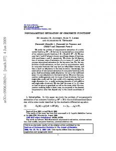
A simple MatLab code (Appendix A) is written to solve the simultaneous equations given in equations (17) and determine all four S -parameters of a composite material slab placed in a rectangular waveguide. In this section, assuming the properties of individual layers of a composite material known, the S -parameters for various composite slabs are computed (using the MatLab code) as a function of frequency and compared with the measured S -parameters. Single Layer Composite Material: Figure 3 shows S11 and S 21 parameters of a composite material consisting of a Garlock single layer as a function of frequency. In this case a single layer of Garlock with thickness ∆ 1 = 0.17cm and electric properties ε r = 7.5 − j 0.001 is used to form a
composite material. Excellent agreement between measured and estimated
Figure 3: Measured and estimated S -parameters of single Garlock slab. Thickness ∆ 1 = 0.17cm , ε r = 7.5 − j 0.001 , µ r = 1.0 − j 0.0 10
values of the S -parameters validates the MatLab code. Figure 4 shows the S11 and S 21 parameters of a composite material formed by a single layer of Teflon material ( ε r = 2.03 − j 0.001 , µ r = 1.0 − j 0.0 ) of thickness ∆ 1 = 0.635cm . A good agreement
between the measured and estimated values of S -parameters confirms validity of the present method. Note that the parameters S 22 and S12 are expected and found to be identical to S11 and S 21 , respectively.
Figure 4: Measured and estimated S -parameters of single teflon slab. Thickness ∆ 1 = 0.635cm , ε r = 2.03 − j 0.001 , µ r = 1.0 − j 0.0
Two Layer Composite Material:
For further validation of the present method and MatLab code, the S -parameters of composite material formed by various combination of two layers are fabricated and tested. A first sample considered consists of Bakelite and Teflon layers.
11
The composite slab is formed by placing the bakelite layer with ∆ 1 = 0.33cm , z 0 = 0 , z1 = 0.33cm and the Teflon layer with ∆ 2 = 0.635cm , z1 = 0.33cm , z 2 = 0.965cm . Measured and estimated S11 and S 21 parameters as a function of
frequency are shown in figure 5. For the composite material described in figure 5, the measured and estimated S 22 and S12 values are shown in figure 6.
Real( S 21 )
Imag.( S11 )
Imag.( S 21 )
Real( S11 )
Figure 5: Measured and estimated S -parameters of two layers composite material (Bakelite-Teflon). Bakelite: ∆ 1 = 0.33cm , z 0 = 0 , z1 = 0.33cm , ε r = 3.76 − j 0.001, µ r = 1.0 , Teflon: ∆ 2 = 0.635cm , z1 = 0.33cm , z 2 = 0.965cm , ε r = 2.03 − j 0.001, µ r = 1
12
Figure 6: Measured and estimated values of S 22 and S12 for composite slab (parameters as described in figure 5)
A second sample of composite material considered consists of Garlock and Nomex materials. The composite slab is formed by placing first a Garlock slab of thickess
∆ 1 = 0.17cm , ε r = 7.5 − j 0.001, µ r = 1.0 at z 0 = 0 and z1 = 0.17cm and then a Nomex slab of thickness ∆ 2 = 0.33cm , ε r = 1.2 − j 0.001, µ r = 1.0 at z1 = 0.17cm and z 2 = 0.5cm . Measured and estimated S11 , S 21 , S12 , and S 22 parameters for Garlock-
Nomex composite slab are shown in figures 7 and 8. From figures 7-8, estimated values of S -parameters for the Garlock-Nomex composite slab agrees well with measured values of the S -parameters. However, for the BakeliteTeflon combination there is small disagreement between measured and estimated S 22 and S12 parameters. This disagreement may be attributed to the presence of an air gap
between the slabs of Bakelite and Teflon.
13
Figure 7: Measured and estimated S -parameters of two layers composite material (Garlock-Nomex). Galock: ∆ 1 = 0.17cm , z 0 = 0 , z1 = 0.17cm , ε r = 7.5 − j 0.001, µ r = 1.0 , Nomex ∆ 2 = 0.33cm , z1 = 0.17cm , z 2 = 0.50cm , ε r = 1.2 − j 0.001, µ r = 1
Figure 8: Measured and estimated S-parameters of two layers composite material (Garlock-Nomex) with dimensions as shown in Figure 7
14
Three Layer Composite Material:
A third sample of composite material considered consists of Nano Material # 0, Garlock and Garlock slabs. The composite slab is formed by placing first a Nano Material #0 slab of thickess ∆1 = 0.31cm , ε r = 2.5 − j 0.001, µ r = 1.0 at z 0 = 0 and z1 = 0.31cm and then a Garlock slab of thickness ∆ 2 = 0.17cm ,
ε r = 7.5 − j 0.001, µ r = 1 , at z1 = −.31cm , and z 2 = 0.48cm . Another Garlock slab of thickness ∆ 1 = 0.17cm , ε r = 7.5 − j 0.001, µ r = 1.0 is placed at z 2 = 0.48cm and z 3 = 0.65cm . Figures 9-10 show measured and estimated S -parameters of composite
slab consisting of Nano_Mat #0-Garlock-Garlock combination.
Figure 9: Measured and estimated S11 and S 21 parameters of composite slab consisting of Nano-Material#0, Garlock, and Garlock(Dimensions as described in text)
15
Figure 10: Measured and estimated S 22 and S12 parameters of composite slab consisting of Nano-Material#0, Garlock, and Garlock(Dimensions as described in text)
From figures 9-10, the trend in the values of S -parameters predicted by the computation is similar to the trend observed in the measured values. However, significant differences are observed between the measured and estimated values of S -parameters. This may be attributed to the sample preparation where the presence of air gaps between the individual slabs is unavoidable. Also even though these individual slabs may be in physical contact with each other, electrical contact may still not be insured. It is also noticeable that the disagreement between the measured and estimated S -parameters gets worse as more individual slabs are used to form a composite slab.
16
B: Estimation of Dielectric Constants( Inverse Problem): Single Layer Composite Material: In this section a procedure is described for the computation of the complex dielectric constant of a given composite sample from the two port measured data. For a given composite material sample, let the two port S -parameters be ( S11m , S 21m , S12 m , S 22 m ), measured using the hp-8510 Network Analyzer. With a prior knowledge of the thickness of composite slabs, the two port S -parameters can be estimated using the MatLab Code given in Appendix A as a function of ε r . Let the estimated values of S parameters be S11c (ε r ), S 21c (ε r ), S12c (ε r ), S 22 c (ε r ) . The errors in estimated and measured S -parameters can then be written as ER1 = real ( S11c − S11m ) , ER2 = imag .( S11c − S11m ) ,
ER3 = real ( S 21c − S 21m ) , ER4 = imag .( S 21c − S 21m ) , ….. ER7 = real ( S 22 c − S 22 m ) , ER8 = imag.( S 22c − S 22 m ) . The total mean squared error or the objective function to be minimized as a function of ε r can be written as
ERT = ( ER12 + ER22 + ER32 + ER42 + ER52 + ER62 + ER72 + ER82 )
(19)
A simple MatLab Code given in Appendix B minimizes the objective function in (19) to estimate the unknown value of dielectric constant ε r . Examples (When Thickness of Sample Is Known): Garlock Slab: A single layer of Garlock slab of size (2.29 x 1.02 x 0.17 )cm was placed
in an X-band rectangular waveguide. After proper calibration of the hp 8510 Network Analyzer, two port S-parameters of the Garlock slab were measured as a function of frequency. The measured data is stored in a file FT_GRLK.60. Using the MatLab Code
17
given in the Appendix B, the dielectric constant of the Garlock slab is estimated and shown in figure 11.
Figure 11: Relative dielectric constant (real and imaginary) of Garlock material estimated using measured and ideal Sparameters.
In figure 11 solid and dash-dot lines are the estimates of dielectric constant using the ideal or noise free S-parameters calculated assuming the dielectric constant is known and equal to ε r = 7.5 − j 0.001 . The estimates shown in figure 11 were obtained by
considering the thickness of the slab equal to 0.170cm. To check the level of confidence in these estimates, from the estimated values of dielectric constant (estimated using the measured data), the difference between measured and computed values of S-parameters is plotted in Figure 12.
18
(Sc-Sm) Parameters Figure 12: Differences between computed and measured values of Sparameters. Calculated S-parameters are determined using estimated dielectric constant The differences between the computed and measured S-parameters are within the limits set in the optimizer. Ideally, the difference between the computed and measured Sparameters must be close to zero. However, to achieve ideal results, the optimizer would take longer time. Number of single layer composite materials of various material and thickness were constructed and their S-parameters were measured over the X-band frequency range. From these measured values of S-parameters and using the MatLab Code given in Appendix B, the dielectric constants of these single layer composite were estimated and presented in figures 13-25.
19
Figure 13: Relative dielectric constant (real and imaginary) of Nano material #0 estimated using measured and ideal S-parameters (thickness = 0.3099 cm)
Figure 14: Relative dielectric constant (real and imaginary) of Teflon material estimated using measured and ideal S-parameters (thickness = 0.9398 )
20
Figure 15: Relative dielectric constant (real and imaginary) of Cork material estimated using measured and ideal S-parameters (thickness = 0.3048cm)
Figure 16: Relative dielectric constant (real and imaginary) of Ceramic material estimated using measured and ideal S-parameters (thickness = 0.2845 cm)
21
Figure 17: Relative dielectric constant (real and imaginary) of Nomex Felt material estimated using measured and ideal Sparameters (thickness = 0.33cm)
Figure 18: Relative dielectric constant (real and imaginary) of Rubylith material estimated using measured and ideal S-parameters (thickness = 0.3683 cm)
22
Figure 19: Relative dielectric constant (real and imaginary) of Bakelite material estimated using measured and ideal S-parameters (thickness = 0.33cm
Figure 20: Relative dielectric constant (real and imaginary) of Fiber Glass material estimated using measured and ideal S-parameters (thickness = 0.0533cm 23
Figure 21: Relative dielectric constant (real and imaginary) of Woven Composite B material estimated using measured and ideal S-parameters (thickness = 0.1625cm
Figure 22: Relative dielectric constant (real and imaginary) of low density Foam material estimated using measured and ideal S-parameters (thickness = 0.2921cm)
24
Figure 23: Relative dielectric constant (real and imaginary) of Woven Composite G material estimated using measured and ideal S-parameters (thickness = 0.2083 cm) Examples (When Thickness of Sample Is Unknown): In the previous section it was assumed that the thickness of the sample is known apriori. These thicknesses are measured in the laboratory using an electronic micrometer. However, for compressible and thin samples the accuracy of these measurements is questionable. In this section it is assumed that the thickness of the sample is unknown and the optimizer is asked to estimate the thickness along with the dielectric constant of a single layer composite material slab. The MatLab Code used for estimation of sample thickness as well as dielectric constant is given in Appendix B. Garlock Slab: The measured data stored in a file FT_GRLK.60 is used to estimate the thickness of Garlock slab and dielectric constants. Using the MatLab Code given in the Appendix B, the dielectric constant of the Garlock slab and its thickness are estimated and shown in figure 24.
25
Figure 24: Relative dielectric constant (real and imaginary) of Garlock material estimated assuming thickness unknown. Symbols indicate estimated values of dielectric constant using thickness = 0.17 cm. Thin solid line indicate estimated value of sample thickness.
In figure 24, estimated values of the dielectric constant assuming sample thickness unknown are in close agreement with the dielectric constant estimated assuming known value of sample thickness. The average value of estimated sample thickness is 0.1699 cm which is very close to the actual measured thickness of 0.1702cm. This validates the idea that apriori knowledge of sample thickness is not necessary for the inverse problem. In fact the thickness of the sample can be considered as one of the unknown variables along with the dielectric constants to optimize the error function defined in (19). Using the
26
(Sc-Sm) Parameters
Figure 25: Differences between computed and measured values of Sparameters. Calculated S-parameters are determined using estimated dielectric constant and thickness of the slab
estimated values of dielectric constants and the sample thickness, the difference between measured and computed values of S-parameters is plotted in Figure 25. The differences between the computed and measured S-parameters are within the limits set in the optimizer. Ideally, the difference between the computed and measured Sparameters must be close to zero. However, to achieve ideal results, the optimizer would take a longer time. From the measured values of the S-parameters for a variety of single layer composite materials (Nano Material #0, Cork, Ceramic, Nomex Felt, Rubylith, Bakelite, Teflon, Fiber Glass, Woven Composite B and G, Nano Material # 0) the dielectric constants and thicknesses of the material are estimated using the MatLab Code given in Appendix B. These estimated values are shown in figures 26-36. For comparison, the estimated values of dielectric constants using MatLab Code given in Appendix B are also plotted in figures 26-36. The estimated values of dielectric constants assuming the thickness unknown are in good agreement with the estimates obtained using known
27
values of dielectric constants. From the figures 26-36 it may be concluded that the thickness of a single layer slab can be treated as one of the unknown variables along with the dielectric constants.
Figure 26: Relative dielectric constant (real and imaginary) of Nano material #0 estimated assuming thickness unknown. Symbols indicate estimated values of dielectric constant using thickness = 0.301 cm. Thin solid line indicate estimated value of sample thickness.
28
Figure 27: Relative dielectric constant (real and imaginary) of Cork material estimated assuming thickness unknown. Symbols indicate estimated values of dielectric constant using thickness = 0.3048 cm. Thin solid line indicate estimated value of sample thickness.
Figure 28: Relative dielectric constant (real and imaginary) of Ceramic material estimated assuming thickness unknown. Symbols indicate estimated values of dielectric constant using thickness = 0.2845 cm. Thin solid line indicate estimated value of sample thickness.
29
Figure 29: Relative dielectric constant (real and imaginary) of Nomex Felt material estimated assuming thickness unknown. Symbols indicate estimated values of dielectric constant using thickness = 0.3302 cm. Thin solid line indicate estimated value of sample thickness.
Figure 30: Relative dielectric constant (real and imaginary) of Rubylith material estimated assuming thickness unknown. Symbols indicate estimated values of dielectric constant using thickness = 0.3683 cm. Thin solid line indicate estimated value of sample thickness.
30
Figure 31: Relative dielectric constant (real and imaginary) of Bakelite material estimated assuming thickness unknown. Symbols indicate estimated values of dielectric constant using thickness = 0.3302 cm. Thin solid line indicate estimated value of sample thickness.
Figure 32: Relative dielectric constant (real and imaginary) of Teflon material estimated assuming thickness unknown. Symbols indicate estimated values of dielectric constant using thickness = 0.9398 cm. Thin solid line indicate estimated value of sample thickness.
31
Figure 33: Relative dielectric constant (real and imaginary) of Fiber Glass material estimated assuming thickness unknown. Symbols indicate estimated values of dielectric constant using thickness = 0.0533 cm. Thin solid line indicate estimated value of sample thickness.
Figure 34: Relative dielectric constant (real and imaginary) of Foam material estimated assuming thickness unknown. Symbols indicate estimated values of dielectric constant using thickness = 0.2921 cm. Thin solid line indicate estimated value of sample thickness.
32
Figure 35: Relative dielectric constant (real and imaginary) of Woven Composite B material estimated assuming thickness unknown. Symbols indicate estimated values of dielectric constant using thickness = 0.1626 cm. Thin solid line indicate estimated value of sample thickness.
Figure 36: Relative dielectric constant (real and imaginary) of Woven Composite G material estimated assuming thickness unknown. Symbols indicate estimated values of dielectric constant using thickness = 0.2083 cm. Thin solid line indicate estimated value of sample thickness. 33
Most of estimated dielectric constants determined assuming thickness unknown agree well with the dielectric constants estimated using measured value of slab thickness. However, in figure 33, the two results disagree significantly. This is because the thickness of the slab is very small. In fact, the S-parameters calculated using estimated thickness and the dielectric constants agree very well with the measurements as shown in figure 37.
Figure 37: Measured and computed S-parameters for Fiber Glass Material. Computed S-parameters are determined using estimated values of dielectric constant and thickness of Fiber Glass.
Two Layer Composite Material: In this section measured S-parameters of composite material consisting of two material layers are used to estimate the dielectric constants of individual layers. The error or objective function used for this purpose is identical to equation (19). The MatLab Code
34
given in Appendix B, with proper input variables is used to estimate the dielectric constants of two layers. Examples:(Thickness of Layers Known): A two layer composite material consisting of Bakelite and Teflon was formed by placing first the Bakelite layer of thickness ∆ 1 = 0.33cm between the z 0 = 0 and z1 = 0.33cm
planes. A Teflon layer of thickness ∆ 2 = 0.635cm was then placed between z1 = 0.33cm and z 2 = 0.965cm . The measured values of S-parameters of the Bakelite-Teflon as a function of frequency was stored in a file FT_BKLTEF.60. Using the MatLab Code given in Appendix B, the dielectric constants of the two layers were estimated and plotted in Figure 38.
Figure 38: Relative dielectric constant (real and imaginary) of Bakelite-Teflon Composite material estimated using measured S-parameters (assuming thickness known)
35
Figure 39 shows estimated values of dielectric constants of Bakelite-Teflon Composite material using the ideal S-parameter values computed using the MatLab Code given in Appendix A. Figure 40 shows the error involved in the estimations of dielectric constants using measured and ideal values of S-parameters. From figure 40 it is clear that the error in estimation using the measured S-parameters is higher than the error involved in the estimation using ideal S-parameters. This may be attributed to the noise present in the measured data and inability of the analytical model to take into account potential air gaps present between the two layers.
Figure 39: Relative dielectric constant (real and imaginary) of Bakelite-Teflon Composite material estimated using ideal S-parameters (assuming thickness known)
36
Objective/Error Function
Figure 40: Value of error function given in (19) in estimating the dielectic constants of Bakelite-Teflon Composite using both measured and ideal Sparameters
For further verifications of the present approach for a two layer composite material the following samples were considered: 1) Garlock-Nomex Felt: ∆ 1 = 0.17cm , ∆ 2 = 0.33cm , z 0 = 0.0 , z1 = 0.17cm , z 2 = 0.5cm
2) Garlock-Ceramic: ∆ 1 = 0.17cm , ∆ 2 = 0.2845cm , z 0 = 0.0 , z1 = 0.17cm , z 2 = 0.4545cm
3) Garlock-Nano Material #0 : ∆ 1 = 0.17cm , ∆ 2 = 0.3099cm , z 0 = 0.0 , z1 = 0.17cm , z 2 = 0.4799cm
37
4) Garlock-Woven Composite G: ∆ 1 = 0.17cm , ∆ 2 = 0.2083cm , z 0 = 0.0 , z1 = 0.17cm , z 2 = 0.3783cm
5) Garlock-Bakelite ∆ 1 = 0.17cm , ∆ 2 = 0.33cm , z 0 = 0.0 , z1 = 0.17cm , z 2 = 0.50cm .
For these samples the relative dielectric constants of individual layer were estimated from the measured and ideal S-parameters. Estimated values of relative dielectric constants are shown in figures 41-56.
Figure 41: Relative dielectric constant (real and imaginary) of Garlock-Nomex Felt Composite material estimated using measured S-parameters (assuming thickness known)
38
Figure 42: Relative dielectric constant (real and imaginary) of Garlock – Nomex Felt Composite material estimated using ideal S-parameters (assuming thickness known)
Figure 43: Value of error function given in (19) in estimating the dielectic constants of Garlock –Nomex Felt Composite using both measured and ideal S-parameters.
39
Figure 44: Relative dielectric constant (real and imaginary) of Garlock-Ceramic Composite material estimated using measured S-parameters (assuming thickness known)
Figure 45: Relative dielectric constant (real and imaginary) of Garlock – Ceramic Composite material estimated using ideal S-parameters (assuming thickness known)
40
Figure 46: Value of error function given in (19) in estimating the dielectic constants of Garlock –Ceramic Composite using both measured and ideal S-parameters.
Figure 47: Relative dielectric constant (real and imaginary) of Garlock-Nano Material #0 Composite material estimated using measured S-parameters (assuming thickness known) 41
Figure 48: Relative dielectric constant (real and imaginary) of Garlock – Nano Material #0 Composite material estimated using ideal S-parameters (assuming thickness known)
Figure 49: Value of error function given in (19) in estimating the dielectic constants of Garlock –Nano Material #0 Composite using both measured and ideal S-parameters.
42
Figure 50: Relative dielectric constant (real and imaginary) of Garlock-Woven Composite G material estimated using measured S-parameters (assuming thickness known)
Figure 51: Relative dielectric constant (real and imaginary) of Garlock – Woven Composite G material estimated using ideal S-parameters (assuming thickness known) 43
Figure 52: Value of error function given in (19) in estimating the dielectic constants of Garlock –Woven Composite G material using both measured and ideal S-parameters.
Figure 53: Relative dielectric constant (real and imaginary) of Garlock-Bakelite Composite material estimated using measured S-parameters (assuming thickness known) 44
Objective/Error Function
Figure 54: Relative dielectric constant (real and imaginary) of Garlock – Bakelite Composite material estimated using ideal S-parameters (assuming thickness known)
Figure 55: Value of error function given in (19) in estimating the dielectic constants of Garlock –Bakelite Composite material using both measured and ideal S-parameters. 45
From the results shown in figures 41-55, it may be concluded that the method presented in this report can successfully estimate dielectric constants of two layer composite material with apriori knowledge of the thickness of individual layers. An attempt was made to estimate thicknesses of individual layers along with their dielectric constants using the MatLab Code given in Appendix B. However, the optimizer did not estimate these values correctly and hence the results for such cases are not presented. Three Layer Composite Material: In this section measured S-parameters of composite material consisting of three material layers are used to estimate dielectric constants of individual layers. The error or objective function used for this purpose is identical to equation (19). The MatLab Code given in Appendix B, with proper input variables is used to estimate the dielectric constants of two layers. Examples:(Thickness of Layers Known): A three layer composite material consisting of layers of Nano Material #0, Garlock, and Garlock was formed by placing the Nano Material #0 layer of thickness
∆1 = 0.3099cm between z 0 = 0 and z1 = 0.3099cm planes, the Garlock layer of thickness ∆ 2 = 0.17cm between z1 = 0.3099cm and z 2 = 0.4799cm planes, and Garlock layer of thickness ∆ 1 = 0.17cm between z 2 = 0.4799cm and z 3 = 0.6499cm planes. The measured values of S-parameters stored in FT_NANGRKGRK.60 were used to estimate dielectric constants of each individual layers using the MatLab code given in the Appendix B. The estimated values of dielectric constants are shown in Figure 56. The values of dielectric constants of each these material when estimated using single layer measured data were found to be ε r = 2.5 − j 0.00 for the Nano Material #0,
46
ε r = 7.5 − j 0.00 for the Garlock material. However, when the individual dielectric constants are estimated using the measured data for the three layer composite material, these estimates come out to be little different for the earlier estimates. This may be attributed to the presence of airgaps between the layers.
Figure 56: Estimated values of dielectric constants of individual layers from measured values of S-parameters of three layer composite slab (Nano Material #0-Garlock-Garlock)
Figure 57: Final values of error function in estimation of dielectric constants of individual layers shown in Figure 56 47
The final value of error function or objective function for the estimation shown in Figure 56 is shown in Figure 57. A second example of three layer composite material considered was formed by three layers of the same Garlock slabs. The first Garlock slab of thickness ∆ 1 = 0.17cm was
placed between the z 0 = 0 and z1 = 0.17cm planes, second Garlock layer of thickness ∆ 2 = 0.17cm was placed between z1 = 0.17cm and z 2 = 0.34cm planes, and the third
Garlock layer of thickness ∆ 1 = 0.17cm between z 2 = 0.34cm and z 3 = 0.51cm planes. The measured values of S-parameters stored in FT_GRKGRKGRK.60 were used to estimate dielectric constants of each individual layers using the MatLab code given in Appendix B. The estimated values of dielectric constants are shown in Figure 58. The values of estimated dielectric constants of each individual layers must be close to
ε r = 7.5 − j 0.00 . However, the results shown in the Figure 58 are widely spread around the correct value of the dielectric constant. This discrepancy in the estimated values derived using the measured S-parameters of multilayer composite material is attributed to the measurement errors caused by the airgaps between the layers. The error function or objective function at the final values of dielectric estimates is shown in Figure 59.
48
are Number of The dielectric constants of individual layers of materials are The thicknesses of individual layers in a composite material can be assumed to unkno
Figure 58: Estimated values of dielectric constants of individual layers from measured values of S-parameters of three layer composite slab (Garlock-GarlockGarlock)
Figure 59: Final values of error function in estimation of dielectric constants of individual layers shown in Figure 58
49
IV Conclusion A simple waveguide mode matching method in conjunction with the fminsearch MatLab optimization search function has been presented to estimate the complex permitivity of multi-layer composite material. A multi-layer composite material is placed in an X-band rectangular waveguide and its two-port S-parameters are measured over the X-band using hp-8510 Network Analyzer. For the same composite material using the simple mode matching technique the two port S-parameters are calculated as a function of complex dielectric constants and thicknesses of each layer. The fminsearch function available in the MatLab Optimization Tools is then used to determine complex dielectric constants of each layers assuming the thicknesses of each layer are unknown. The present approach has been validated using number of composite material configurations. The composite material formed by single layers of Garlock, Cork, Ceramic, Nomex Felt, Woven Composite B and G, Rubylith, Bakelite, Teflon, Fiber Glass, Foam, Nano Material have been tested using the present method. The estimated values of dielectric constants and their thicknesses have been found to agree well with the true values supplied by the manufacturers.
The composite materials formed by placing
two layers of the above basic materials have been tested using the present method. The dielectric constants of individual layers estimated have been found to be in good agreement with their values specified by manufacturers.
However, for the composite
material consisting of more than one layer it was assumed that the thicknesses of individual layers were known.
It has been observed that the present method could not
estimate the dielectric constants of individual layers correctly when three of more layers were used to form a composite material. This is attributed to the fact that the airgap
50
present in the measurement samples could not be accurately modelled in the estimation model leading to an incorrect estimation of dielectric constants
Acknowledgement The authors would like to acknowledge the assistance of Mr. Nima Pirzadeh, NASA, LARSS , 2001 summer student, in performing extensive 2-port S-parameter measurement on various composite materials using the hp-8510 Network Analyzer.
References [1] [2]
[3]
[4]
[5]
[6]
[7]
[8]
K. C. Gupta and P. S. Hall, “Analysis and design of integrated circuit antenna modules,” John Wiley & Sons, Inc. , New York, 2000. S. Chakravarty and R. Mittra, ”Application of microgenetic algorithm to the design of spatial fileters with frequency selective surfaces embedded in dielectric media, ” IEEE Trans. On Electromagnetic Compatability, Vol. 44, No. 2 pp. 338346, May 2002 S. Chakravarty, et. al., “Application of a microgenetic algorithm (MGA) to the design of broad-band microwave absorbers using multiple frequency selective surface screens buried in dielectrics, ” IEEE Trans. On Antennas and Propagation, Vol. AP-50, No.3, pp. 284-296, March 2002 E. Michielssen, et al., “Design of light-weight broad-band microwave absorber using genetic algorithms, ” IEEE Trans. Microwave Theory and Techniques, Vol. MTT-41, pp 1024-1031, June 1993 James Baker-Jarvis, “ Dielectric and magnetic meaasurement methods in transmission lines: an overview, ” Proceedings of the 1992 AMTA Workshop, July 25, 1992, Chicago, Illinios. Leo P. Ligthart, “A fast computational technique for accurate permittivity determination using transmission line methods, ” IEEE Trans. On Microwave Theory and Techniques, Vol. MTT-31, No. 3, pp. 249-254, March 1983 R. L. Cravey et al., “Dielectric property measurements in the electromagnetic properties measurement laboratory, ” NASA Technical Memorandom 110147, April 1995. M. D. Deshpande et al., “A new approach to estimate complex permittivity of dielectric materials at microwave frequencies using waveguide measurements, ” IEEE Trans. On Microwave Theory and Techniques, Vol. MTT-45, No. 3, pp. 359-366, March 1997
51
Appendix A: MatLab code for estimation of S-parameters of multilayer substrate placed in a rectangular waveguide. % This program calculates S-parameters of % N-layer composite material placed in an % X-band rectangular waveguide as a function % of frequency. Waveguide dimensions (2.29 cm x 1.02 cm) %Select 201 frequency points over 8.2-12.4 GHz %Frequency band. delf = (12.4-8.2)/201; for j = 1:201 fr(j) = 8.2 +(j-1)*delf; end %Input number of layers n1 = input('n1 = '); %Input dielectric constants for k = 1:2*n1 %First value is real part of dielectric constant %second value is imaginary part of dielectri constant x0(k) = input('x0(k) ='); end %Input location of interfaces for k = 1:n1+1 zn(k) = input('zn(k) ='); end % Set dielectric constants depending upon % number of layers. Only 4 layers are % included. If n1 > 4 then add condition % for given n1 if n1 == 1 er(1) = x0(1) -i*x0(2); end if n1 == 2 er(1) = x0(1) -i*x0(2); er(2) = x0(3) -i*x0(4); end if n1 == 3 er(1) = x0(1) -i*x0(2); er(2) = x0(3) -i*x0(4); er(3) = x0(5)-i*x0(6); end
52
if n1 == 4 er(1) = x0(1) -i*x0(2); er(2) = x0(3) -i*x0(4); er(3) = x0(5)-i*x0(6); er(4) = x0(7)-i*x0(8); end nlayer = n1; %number of layers redifined n = nlayer+1; % Matrix order t =zeros(n,1); % Right handside column matrix initilized s =zeros(n); % Admittance matrix initilized ak =zeros(n,1); % propagation column matrix %Set dielectric constants redifined %const is set to zeros (3 by 3) const = zeros(n); % Dimensions of x-band waveguide in cm aa = 2.29; bb = 1.02; %guide dimensions % Free space dielectric constant e0 = 1.e-9/(36*pi); %f = 8.2e9 %frequency of microwave signal c = 3.e10; % velocity of light in meters/second u0 =4*pi*1.e-7; % Magnetic permeability of free space n0 = (u0/e0)^.5; % Free space impedance for ifr = 1:201 freq = fr(ifr); % Frequency in GHz
ak0 =2*pi*freq/30; %wave number in free space % This loop calculates propagation % constants in layers for k1 = 1:n1 const(k1) = ak0*ak0*(er(k1))-(pi/aa)^2; if (real(const(k1)) < 0.0) ak(k1) = -i*(-const(k1))^.5; else ak(k1) = (const(k1))^.5; end end
% ak00 and ak11 are propagation constants % for the free space regions of waveguide const0 = ak0^2-(pi/aa)^2;
53
if (real(const0) < 0.0) ak00 = -i*(-const0)^.5; else ak00 = (const0)^.5; end ak11 = ak00; for k1 = 1:n1 addm(k1) =ak(k1)./(ak0*n0); end addm00 = ak00/(ak0*n0); addm11 = addm00; % Initilize s matrix for k1= 1:n1+1 for k2 = 1:n1+1 s(k1,k2) = 0.0; end end % LOOP TO CALCULATE IMPEDANCE MATRIX % EXCLUDING FIRST ROW AND LAST ROW for k1 = 2:n1 k2 = k1-1; arg1 = ak(k2)*(zn(k1)-zn(k1-1)); s(k1,k2) = -addm(k2)/(i*sin(arg1)); k2 = k1; arg1 = ak(k2-1)*(zn(k1)-zn(k1-1)); arg2 = ak(k1)*(zn(k1+1)-zn(k1)); s(k1,k2) = addm(k2-1)*cos(arg1)/(i*sin(arg1)) + addm(k1)*cos(arg2)/(i*sin(arg2)); k2 = k1+1; arg2 = ak(k1)*(zn(k1+1)-zn(k1)); s(k1,k2)= -addm(k1)/(i*sin(arg2)); end % FIRST ROW OF IMPEDANCE MATRIX s(1,1) = addm00 + cos(ak(1)*zn(2))/(i*sin(ak(1)*zn(2)))*addm(1); s(1,2) = -addm(1)/(i*sin(ak(1)*zn(2))); % LAST ROW OF IMPEDANCE MATRIX s(nlayer+1,nlayer) = -addm(nlayer)/(i*sin(ak(nlayer) ... *(zn(nlayer+1)-zn(nlayer)))); s(nlayer+1,nlayer+1) = addm(nlayer)*cos(ak(nlayer)* ...
54
(zn(nlayer+1)-zn(nlayer)))/(i*sin(ak(nlayer)* ... (zn(nlayer+1)-zn(nlayer)))) + addm11;
% ONLY FIRST ELEMENT OF RIGHT HAND SIDE % IS NON ZERO for j = 1:nlayer+1 t(j) = 0.0 +i*0.0; end t(1) =2*addm00; % INVERT S AND MULTIPLY BY t T = inv(s)*t; % FIRST ELEMENT OF T - 1 IS REFLECTION % COEFFICIENT AND LAST VALUE OF T is TRANSMISSION % COEFFICIENT % SINCE MEASURED TRANSIMMSION IS REFERENCED TO % INPUT PLANE IT IS MULTIPLIED BY PHASE CORRECTION s11c(ifr) =T(1,1)-1; s21c(ifr) =T(n1+1,1)*exp(i*ak00*zn(n1+1));
end
% CALCULATING S22 AND S12
%Inverse the position of interfaces
if n1 == 1 zn(1) = zn(1); zn(2) = zn(2); er(1) =x0(1) -i*x0(2); end if n1 == 2 zn(1) = -zn(3) + zn(3); zn(2) = -zn(2) + zn(3);
55
zn(3) = -zn(1) + zn(3); er(1) = x0(3) -i*x0(4); er(2) = x0(1) - i*x0(2); end if n1 == 3 zn(1) = -zn(4) + zn(4); zn(2) = -zn(3) + zn(4); zn(3) = -zn(2) + zn(4); zn(4) = -zn(1) + zn(4); er(1) = x0(5) -i*x0(6); er(2) = x0(4) -i*x0(3); er(3) = x0(1) -i*x0(2); end if n == 4 zn(1) = -zn(5) + zn(5); zn(2) = -zn(4) + zn(5); zn(3) = -zn(3) + zn(5); zn(2) = -zn(2) + zn(5); zn(1) = -zn(1) + zn(5); er(1) = x0(7) -i*x0(8); er(2) = x0(5) -i*x0(6); er(3) = x0(3) -i*xo(4); er(4) = x0(1) - i*x0(2); end nlayer = n1; %number of layers redifined n = nlayer+1; % Matrix order t =zeros(n,1); % Right handside column matrix initilized s =zeros(n); % Admittance matrix initilized ak =zeros(n,1); % propagation column matrix %Set dielectric constants redifined %const is set to zeros (3 by 3) const = zeros(n); aa = 2.29; bb = 1.02; %guide dimensions % Free space dielectric constant e0 = 1.e-9/(36*pi); %f = 8.2e9 %frequency of microwave signal c = 3.e10; % velocity of light in meters/second u0 =4*pi*1.e-7; % Magnetic permeability of free space n0 = (u0/e0)^.5; % Free space impedance for ifr = 1:201
56
freq = fr(ifr); % Frequency in GHz ak0 =2*pi*freq/30; %wave number in free space % This loop calculates propagation % constants in layers for k1 = 1:n1 const(k1) = ak0*ak0*(er(k1))-(pi/aa)^2; if (real(const(k1)) < 0.0) ak(k1) = -i*(-const(k1))^.5; else ak(k1) = (const(k1))^.5; end end % ak00 and ak11 are propagation constants % for the free space regions of waveguide const0 = ak0^2-(pi/aa)^2; if (real(const0) < 0.0) ak00 = -i*(-const0)^.5; else ak00 = (const0)^.5; end ak11 = ak00; %calculate addmitince for layers: for k1 = 1:n1 addm(k1) =ak(k1)./(ak0*n0); end addm00 = ak00/(ak0*n0); addm11 = addm00; % Initilize s matrix for k1= 1:n1+1 for k2 = 1:n1+1 s(k1,k2) = 0.0; end end % LOOP TO CALCULATE IMPEDANCE MATRIX % EXCLUDING FIRST ROW AND LAST ROW for k1 = 2:n1 k2 = k1-1; arg1 = ak(k2)*(zn(k1)-zn(k1-1)); s(k1,k2) = -addm(k2)/(i*sin(arg1)); k2 = k1; arg1 = ak(k2-1)*(zn(k1)-zn(k1-1)); arg2 = ak(k1)*(zn(k1+1)-zn(k1)); s(k1,k2) = addm(k2-1)*cos(arg1)/(i*sin(arg1)) + addm(k1)*cos(arg2)/(i*sin(arg2));
57
k2 = k1+1; arg2 = ak(k1)*(zn(k1+1)-zn(k1)); s(k1,k2)= -addm(k1)/(i*sin(arg2)); end % FIRST ROW OF IMPEDANCE MATRIX s(1,1) = addm00 + cos(ak(1)*zn(2))/(i*sin(ak(1)*zn(2)))*addm(1); s(1,2) = -addm(1)/(i*sin(ak(1)*zn(2))); % LAST ROW OF IMPEDANCE MATRIX s(nlayer+1,nlayer) = -addm(nlayer)/(i*sin(ak(nlayer) ... *(zn(nlayer+1)-zn(nlayer)))); s(nlayer+1,nlayer+1) = addm(nlayer)*cos(ak(nlayer)* ... (zn(nlayer+1)-zn(nlayer)))/(i*sin(ak(nlayer)* ... (zn(nlayer+1)-zn(nlayer)))) + addm11;
% ONLY FIRST ELEMENT OF RIGHT HAND SIDE % IS NON ZERO for j = 1:nlayer+1 t(j) = 0.0 -i*0.0; end t(1) =2*addm00; % INVERT S AND MULTIPLY BY t T = inv(s)*t; % FIRST ELEMENT OF T - 1 IS REFLECTION % COEFFICIENT AND LAST VALUE OF T is TRANSMISSION % COEFFICIENT % SINCE MEASURED TRANSIMMSION IS REFERENCED TO % INPUT PLANE IT IS MULTIPLIED BY PHASE CORRECTION ref =T(1,1)-1; s22c(ifr) = ref*exp(i*ak00*2*zn(n1+1)); s12c(ifr) =T(n1+1,1)*exp(i*ak00*zn(n1+1));
end ss = load('FT_GRLK.60');
58
delf = (12.4-8.2)/201; for j = 1:201 fr(j) = 8.2 +(j-1)*delf; end for j = 1:201 s11r(j) = ss(j,1); s11i(j) = ss(j,2); s21r(j) = ss(j+201,1); s21i(j) = ss(j+201,2); s12r(j) = ss(j+402,1); s12i(j) = ss(j+402,2); s22r(j) = ss(j+603,1); s22i(j) = ss(j+603,2); end plot(fr,s11r,fr,s11i,fr,real(s11c),fr,imag(s11c)) ok = input('Is plot ok ='); plot(fr,s21r,fr,s21i,fr,real(s21c),fr,imag(s21c)) ok = input('Is plot ok ='); plot(fr,s12r,fr,s12i,fr,real(s12c),fr,imag(s12c)) ok = input('Is plot ok ='); plot(fr,s22r,fr,s22i,fr,real(s22c),fr,imag(s22c)) ok = input('Is plot ok =');
%
59
Appendix B: MatLab code for estimation of dielectric parameters of multilayer substrate placed in a rectangular waveguide.
% This program estimates dielectric parameters of % multi-layer substrate . Measured data has to be loaded in % meas.dat file % X-band rectangular waveguide as a function % of frequency. %Load measured data file ss = load('meas.dat');
delf = (12.4-8.2)/201; for j = 1:201 fr(j) = 8.2 +(j-1)*delf; end %Input number of layers n1 = input('n1 = '); %Input dielectric constants for k = 1:2*n1 %First value is real part of dielectric constant %second value is imaginary part of dielectri constant x0(k) = input('x0(k) ='); end %Input location of interfaces for k = 1:n1+1 zn(k) = input('zn(k) ='); end for j = 1:201 s11r(j) = ss(j,1); s11i(j) = ss(j,2); s21r(j) = ss(j+201,1); s21i(j) = ss(j+201,2); s12r(j) = ss(j+402,1); s12i(j) = ss(j+402,2); s22r(j) = ss(j+603,1);
60
s22i(j) = ss(j+603,2); end % CHECK WHETHER SYSTEM IS LOSSLESS OR LOSSY for j = 1:201 s11 = s11r(j)+i*s11i(j); s21 = s21r(j)+i*s21i(j); s12 = s12r(j)+i*s12i(j); s22 = s22r(j)+i*s22i(j); freq = fr(j);
x0 = [1.0;0.0;1.0;0.0;1.0;0.0]; options = optimset('Display', 'iter', 'MaxFunEvals' , 1000, 'TolFun', 1.e-08) options = optimset('TolX', 1e-08) [x,fval,flag] = fminsearch(@obj_ref,x0,options,s11,s21,s12,s22,freq,n1 ... ,zn); er11(j) = x(1); er12(j) = x(2); er21(j) = x(3); er22(j) = x(4); er31(j) = x(5); er32(j) = x(6); fg1(j) = fval; flag end outmat = [fr.',er11.',er12.']; save('temp1','outmat','-ascii') outmat = [fr.',er21.',er22.']; save('temp2','outmat','-ascii') outmat = [fr.',er31.',er32.']; save('temp3','outmat','-ascii') outmat =[fr.',fg1.']; save('temp4','outmat','-ascii')
%
61
% This is object function function f = obj_ref(x0,s11,s21,s12,s22,freq,n1,zn) if n1 == 1 er(1) = x0(1) - i*x0(2); end if n1 == 2 er(1) = x0(1) -i*x0(2); er(2) = x0(3) -i*x0(4); end if n1 ==3 er(1) = x0(1) -i*x0(2); er(2) = x0(3) -i*x0(4); er(3) = x0(5) -i*x0(6); end if n1 ==4 er(1) = x0(1) -i*x0(2); er(2) = x0(3) -i*x0(4); er(3) = x0(5) -i*x0(6); er(4) = x0(7) -i*x0(8); end
nlayer = n1; %number of layers redifined n = nlayer+1; % Matrix order t =zeros(n,1); % Right handside column matrix initilized s =zeros(n); % Admittance matrix initilized ak =zeros(n,1); % propagation column matrix %Set dielectric constants redifined %const is set to zeros (3 by 3) const = zeros(n); aa = 2.29; bb = 1.02; %guide dimensions % Free space dielectric constant e0 = 1.e-9/(36*pi); %f = 8.2e9 %frequency of microwave signal c = 3.e10; % velocity of light in meters/second u0 =4*pi*1.e-7; % Magnetic permeability of free space n0 = (u0/e0)^.5; % Free space impedance
62
%for ifr = 1:201 %freq = fr(ifr); % Frequency in GHz ak0 =2*pi*freq/30; %wave number in free space % This loop calculates propagation % constants in three layers for k1 = 1:n1 const(k1) = ak0*ak0*(er(k1))-(pi/aa)^2; if (real(const(k1)) < 0.0) ak(k1) = -i*(-const(k1))^.5; else ak(k1) = (const(k1))^.5; end end const0 = ak0^2-(pi/aa)^2; if (real(const0) < 0.0) ak00 = -i*(-const0)^.5; else ak00 = (const0)^.5; end ak11 = ak00; %calculate addmitince for layers: for k1 = 1:n1 addm(k1) =ak(k1)./(ak0*n0); end addm00 = ak00/(ak0*n0); addm11 = addm00; % Initilize s matrix for k1= 1:n1+1 for k2 = 1:n1+1 s(k1,k2) = 0.0; end end % LOOP TO CALCULATE IMPEDANCE MATRIX % EXCLUDING FIRST ROW AND LAST ROW for k1 = 2:n1 k2 = k1-1; arg1 = ak(k2)*(zn(k1)-zn(k1-1)); s(k1,k2) = -addm(k2)/(i*sin(arg1)); k2 = k1; arg1 = ak(k2-1)*(zn(k1)-zn(k1-1)); arg2 = ak(k1)*(zn(k1+1)-zn(k1)); s(k1,k2) = addm(k2-1)*cos(arg1)/(i*sin(arg1)) + addm(k1)*cos(arg2)/(i*sin(arg2)); k2 = k1+1;
63
arg2 = ak(k1)*(zn(k1+1)-zn(k1)); s(k1,k2)= -addm(k1)/(i*sin(arg2)); end % FIRST ROW OF IMPEDANCE MATRIX s(1,1) = addm00 + cos(ak(1)*zn(2))/(i*sin(ak(1)*zn(2)))*addm(1); s(1,2) = -addm(1)/(i*sin(ak(1)*zn(2))); % LAST ROW OF IMPEDANCE MATRIX s(nlayer+1,nlayer) = -addm(nlayer)/(i*sin(ak(nlayer) ... *(zn(nlayer+1)-zn(nlayer)))); s(nlayer+1,nlayer+1) = addm(nlayer)*cos(ak(nlayer)* ... (zn(nlayer+1)-zn(nlayer)))/(i*sin(ak(nlayer)* ... (zn(nlayer+1)-zn(nlayer)))) + addm11;
% ONLY FIRST ELEMENT OF RIGHT HAND SIDE % IS NON ZERO for j = 1:nlayer+1 t(j) = 0.0+i*0.0; end t(1) =2*addm00; % INVERT S AND MULTIPLY BY t T = inv(s)*t; % FIRST ELEMENT OF T - 1 IS REFLECTION % COEFFICIENT AND LAST VALUE OF T is TRANSMISSION % COEFFICIENT % SINCE MEASURED TRANSIMMSION IS REFERENCED TO % INPUT PLANE IT IS MULTIPLIED BY PHASE CORRECTION s11c =T(1,1)-1; s21c =T(n1+1,1)*exp(i*ak00*zn(n1+1)); f = real(s11c-s11)*real(s11c-s11) + imag(s11c-s11)*imag(s11c-s11) ... +real(s21c-s21)*real(s21c-s21) + imag(s21c-s21)*imag(s21c-s21);
% CALCULATING S22 AND S12
64
if n1 == 1 zn1(1) = zn(2) - zn(2); zn1(2) = zn(2) - zn(1); end if n1 == 2 zn1(1) = zn(3) - zn(3); zn1(2) = zn(3) - zn(2); zn1(3) = zn(3) - zn(1); end if n1 == 3 zn1(1) = zn(4) - zn(4); zn1(2) = zn(4) - zn(3); zn1(3) = zn(4) - zn(2); zn1(4) = zn(4) - zn(1); end if n1 == 4 zn1(1) = zn(5) - zn(5); zn1(2) = zn(5) - zn(4); zn1(3) = zn(5) - zn(3); zn1(4) = zn(5) - zn(2); zn1(5) = zn(5) - zn(1); end
if n1 == 1 er(1) =x0(1) - i*x0(2); end if n1 == 2 er(2) = x0(1) - i*x0(2); er(1) = x0(3) - i*x0(4); end if n1 ==3 er(1) = x0(5) -i*x0(6); er(2) = x0(3) -i*x0(4); er(3) = x0(1) - i*x0(2); end if n1 ==4 er(1) = x0(7) -i*x0(8); er(2) = x0(5) -i*x0(6); er(3) = x0(3) -i*x0(4); er(4) = x0(1) - i*x0(2); end
65
nlayer = n1; %number of layers redifined n = nlayer+1; % Matrix order t =zeros(n,1); % Right handside column matrix initilized s =zeros(n); % Admittance matrix initilized ak =zeros(n,1); % propagation column matrix %Set dielectric constants redifined %const is set to zeros (3 by 3) const = zeros(n); aa = 2.29; bb = 1.02; %guide dimensions % Free space dielectric constant e0 = 1.e-9/(36*pi); %f = 8.2e9 %frequency of microwave signal c = 3.e10; % velocity of light in meters/second u0 =4*pi*1.e-7; % Magnetic permeability of free space n0 = (u0/e0)^.5; % Free space impedance %for ifr = 1:201 %freq = fr(ifr); % Frequency in GHz ak0 =2*pi*freq/30; %wave number in free space % This loop calculates propagation % constants in three layers for k1 = 1:n1 const(k1) = ak0*ak0*(er(k1))-(pi/aa)^2; if (real(const(k1)) < 0.0) ak(k1) = -i*(-const(k1))^.5; else ak(k1) = (const(k1))^.5; end end %ak %ok = input('ok = ') % ak00 and ak11 are propagation constants % for the free space regions of waveguide const0 = ak0^2-(pi/aa)^2; if (real(const0) < 0.0) ak00 = -i*(-const0)^.5; else ak00 = (const0)^.5; end ak11 = ak00; %ak0 %calculate addmitince for layers: for k1 = 1:n1 addm(k1) =ak(k1)./(ak0*n0); end
66
%addm %ok = input('ok =') addm00 = ak00/(ak0*n0); addm11 = addm00; %addm00 %addm11 %ok = input('ok =') % Initilize s matrix for k1= 1:n1+1 for k2 = 1:n1+1 s(k1,k2) = 0.0; end end % LOOP TO CALCULATE IMPEDANCE MATRIX % EXCLUDING FIRST ROW AND LAST ROW for k1 = 2:n1 k2 = k1-1; arg1 = ak(k2)*(zn1(k1)-zn1(k1-1)); s(k1,k2) = -addm(k2)/(i*sin(arg1)); k2 = k1; arg1 = ak(k2-1)*(zn1(k1)-zn1(k1-1)); arg2 = ak(k1)*(zn1(k1+1)-zn1(k1)); s(k1,k2) = addm(k2-1)*cos(arg1)/(i*sin(arg1)) + addm(k1)*cos(arg2)/(i*sin(arg2)); k2 = k1+1; arg2 = ak(k1)*(zn1(k1+1)-zn1(k1)); s(k1,k2)= -addm(k1)/(i*sin(arg2)); end % FIRST ROW OF IMPEDANCE MATRIX s(1,1) = addm00 + cos(ak(1)*zn1(2))/(i*sin(ak(1)*zn1(2)))*addm(1); s(1,2) = -addm(1)/(i*sin(ak(1)*zn1(2))); % LAST ROW OF IMPEDANCE MATRIX s(nlayer+1,nlayer) = -addm(nlayer)/(i*sin(ak(nlayer) ... *(zn1(nlayer+1)-zn1(nlayer)))); s(nlayer+1,nlayer+1) = addm(nlayer)*cos(ak(nlayer)* ... (zn1(nlayer+1)-zn1(nlayer)))/(i*sin(ak(nlayer)* ... (zn1(nlayer+1)-zn1(nlayer)))) + addm11; %s %ok = input('ok =') % form cpmplex matrix
67
% ONLY FIRST ELEMENT OF RIGHT HAND SIDE % IS NON ZERO for j = 1:nlayer+1 t(j) = 0.0 + i*0.0; end t(1) =2*addm00; % INVERT S AND MULTIPLY BY t T = inv(s)*t; % FIRST ELEMENT OF T - 1 IS REFLECTION % COEFFICIENT AND LAST VALUE OF T is TRANSMISSION % COEFFICIENT % SINCE MEASURED TRANSIMMSION IS REFERENCED TO % INPUT PLANE IT IS MULTIPLIED BY PHASE CORRECTION ref =T(1,1)-1; s22c = ref*exp(i*ak00*2*zn1(n1+1)); s12c =T(n1+1,1)*exp(i*ak00*zn1(n1+1)); f = f+ real(s22c-s22)*real(s22c-s22) +imag(s22c-s22)*imag(s22c-s22) ... + real(s12c-s12)*real(s12c-s12) + imag(s12c-s12)*imag(s12c-s12);
68
Form Approved OMB No. 0704-0188
REPORT DOCUMENTATION PAGE
Public reporting burden for this collection of information is estimated to average 1 hour per response, including the time for reviewing instructions, searching existing data sources, gathering and maintaining the data needed, and completing and reviewing the collection of information. Send comments regarding this burden estimate or any other aspect of this collection of information, including suggestions for reducing this burden, to Washington Headquarters Services, Directorate for Information Operations and Reports, 1215 Jefferson Davis Highway, Suite 1204, Arlington, VA 22202-4302, and to the Office of Management and Budget, Paperwork Reduction Project (0704-0188), Washington, DC 20503.
1. AGENCY USE ONLY (Leave blank)
2. REPORT DATE
3. REPORT TYPE AND DATES COVERED
May 2003
Technical Memorandum
4. TITLE AND SUBTITLE
5. FUNDING NUMBERS
Estimation of Complex Permittivity of Composite Multilayer Material at Microwave Frequency Using Waveguide Measurements
706-31-41-01-00
6. AUTHOR(S)
Manohar D. Deshpande and Kenneth Dudley
7. PERFORMING ORGANIZATION NAME(S) AND ADDRESS(ES)
8. PERFORMING ORGANIZATION REPORT NUMBER
NASA Langley Research Center Hampton, VA 23681-2199
L-18285
9. SPONSORING/MONITORING AGENCY NAME(S) AND ADDRESS(ES)
10. SPONSORING/MONITORING AGENCY REPORT NUMBER
National Aeronautics and Space Administration Washington, DC 20546-0001
NASA/TM-2003-212398
11. SUPPLEMENTARY NOTES
12a. DISTRIBUTION/AVAILABILITY STATEMENT
12b. DISTRIBUTION CODE
Unclassified-Unlimited Subject Category 34 Distribution: Nonstandard Availability: NASA CASI (301) 621-0390 13. ABSTRACT (Maximum 200 words)
A simple method is presented to estimate the complex dielectric constants of individual layers of a multilayer composite material. Using the MatLab Optimization Tools simple MatLab scripts are written to search for electric properties of individual layers so as to match the measured and calculated S-parameters. A single layer composite material formed by using materials such as Bakelite, Nomex Felt, Fiber Glass, Woven Composite B and G, Nano Material #0, Cork, Garlock, of different thicknesses are tested using the present approach. Assuming the thicknesses of samples unknown, the present approach is shown to work well in estimating the dielectric constants and the thicknesses. A number of two layer composite materials formed by various combinations of above individual materials are tested using the present approach. However, the present approach could not provide estimate values close to their true values when the thicknesses of individual layers were assumed to be unknown. This is attributed to the difficulty in modelling the presence of airgaps between the layers while doing the measurement of S-parameters. A few examples of three layer composites are also presented. 14. SUBJECT TERMS
15. NUMBER OF PAGES
Composite Material Characterization, Permittivity and Permeability Measurement
80 16. PRICE CODE
17. SECURITY CLASSIFICATION OF REPORT
Unclassified NSN 7540-01-280-5500
18. SECURITY CLASSIFICATION OF THIS PAGE
Unclassified
19. SECURITY CLASSIFICATION OF ABSTRACT
Unclassified
20. LIMITATION OF ABSTRACT
UL Standard Form 298 (Rev. 2-89)
Prescribed by ANSI Std. Z-39-18 298-102