Open Archive Toulouse Archive Ouverte (OATAO) OATAO is an open access repository that collects the work of Toulouse researchers and makes it freely available over the web where possible.
This is an author -deposited version published in: http://oatao.univ-toulouse.fr/ Eprints ID: 2236
To link to this article: DOI: 10.1109/SURV.2010.021110.00086 URL: http://dx.doi.org/10.1109/SURV.2010.021110.00086
To cite this version: SOMMER Jörg, GUNREBEN Sebastian, MIFDAOUI Ahlem, FELLER Frank, KOHN Martin, SAB Detlef, SCHARF Joachim. Ethernet - a survey on its fields of application. IEEE communications surveys and tutorials, 2010, vol 12 (n° 2). pp. 263-284. ISSN 1553-877X.
Any correspondence concerning this service should be sent to the repository administrator:
[email protected]
1
Ethernet – A Survey on its Fields of Application J¨org Sommer, Sebastian Gunreben, Frank Feller, Martin K¨ohn, Detlef Saß, Joachim Scharf University of Stuttgart, Institute of Communication Networks and Computer Engineering Pfaffenwaldring 47, 70569 Stuttgart, Germany Email:
[email protected] Ahlem Mifdaoui Toulouse University, ISAE 1 place Emile Blouin, 31056 Toulouse, France Email:
[email protected]
Abstract— During the last decades, Ethernet progressively became the most widely used local area networking (LAN) technology. Apart from LAN installations, Ethernet became also attractive for many other fields of application, ranging from industry to avionics, telecommunication, and multimedia. The expanded application of this technology is mainly due to its significant assets like reduced cost, backward-compatibility, flexibility, and expandability. However, this new trend raises some problems concerning the services of the protocol and the requirements for each application. Therefore, specific adaptations prove essential to integrate this communication technology in each field of application. Our primary objective is to show how Ethernet has been enhanced to comply with the specific requirements of several application fields, particularly in transport, embedded and multimedia contexts. The paper first describes the common Ethernet LAN technology and highlights its main features. It reviews the most important specific Ethernet versions with respect to each application field’s requirements. Finally, we compare these different fields of application and we particularly focus on the fundamental concepts and the quality of service capabilities of each proposal.
I. I NTRODUCTION In 1972, Robert Metcalfe and his colleagues at the Xerox Palo Alto Research Center developed a local area network (LAN) technology to interconnect stations, servers, and peripheral devices within the same building using a common bus system [1]. This was the birth of the first version of Ethernet. They improved the throughput of the installed Aloha network [2] by a collision detection algorithm [3] and filed the corresponding patent in 1977 [4]. This was the creation of Ethernet’s media access control protocol carrier sense multiple access with collision detection (CSMA/CD, [5]). Together with Intel and DEC, Xerox first published a modified Ethernet version in 1980, which became the well-known DIX Ethernet II version. The first products were available in the early 1980s. In 1985, the IEEE began to standardize the different versions of Ethernet. They avoided the brand name Ethernet and named the technology 802.3 CSMA/CD [1] instead. Until the mid 1990-ies, several other LAN technologies co-existed with Ethernet, including token ring [6], fiber distributed data interface (FDDI, ANSI X3T9.5), and attached resource computer network (ARCnet, ANSI/ATA 878.1-1999). However, Ethernet succeeded in becoming the dominant LAN
technology for companies as it quickly adapted to upcoming requirements. The main requirements of a LAN technology for a company are planning reliability, future proof hardware, and easy management (i. e. plug-and-play capabilities). This especially includes scalability with respect to network size and link speed as well as simple migration. Consequently, the fast bandwidth evolution in the mid/late 1990-ies while maintaining backward-compatibility laid the fundamentals of Ethernet’s success story. Since its invention, Ethernet’s line rate has evolved from 2.94 Mbps to higher rates: 10 Mbps in the early 1980s (DIX Ethernet II), 100 Mbps in 1995 (IEEE 802.3u), 1 Gbps in 1998 (IEEE 802.3z, [5]), and 10 Gbps in 2002 (IEEE 802.3ae). Currently, the IEEE P802.3ba task force is working on 40 Gbps and 100 Gbps [7]. Figure 1 depicts this bandwidth growth. In addition to installations limited to single departments of large companies, Ethernet became attractive for campus-wide deployments as well as for small companies/offices (SOHO). With an increasing penetration of permanent broadband Internet access, the same applies to residential users. Ethernet’s easy adaptability enabled this success in a wide range of surroundings. For residential users, Ethernet offers plug-nplay operation, requiring hardly any manual configuration. In corporate networks, Ethernet enables highly sophisticated networking as described in the next section. Similarly, Ethernet devices range in their complexity and functionality from simple, widely available mass-market products without much functionality (apart from frame forwarding) to specialized, high-performance and feature-rich devices. Besides wired interconnection, Ethernet also supports the interconnection of wireless technologies, e. g. IEEE 802.11 compliant WiFi [8]. Ethernet seamlessly integrates wired and wireless technologies, since they show both the same logical link layer interface. This flexibility of Ethernet is its key to success in the enterprise and SOHO networks. Furthermore, thanks to its low cost, long lifetime, and easy integration with other network technologies, Ethernet has become an attractive option in other areas, too. Ethernet’s promise of being inexpensive, both in terms of mass-market equipment and simple operation, and its predominance in customer LANs make it interesting for transport network operators. Therefore, Ethernet is an
This work has been submitted to the IEEE for possible publication. Copyright may be transferred without notice, after which this version may no longer be accessible.
2 Bit rate 100 Gbps
Local Area Networks ▪ Corporate LAN ▪ SOHO
100 GbE
10 Gbps
10 GbE
1 Gbps
Gigabit Ethernet
100 Mbps
Transport Networks ▪ Carrier Grade ▪ Ethernet in the First Mile
Fast Ethernet
2000
2010
IX
D
Point-to-Point
D w epa id r t e m in e st nt C alla a in m tion st pu s al la s-w tio i ns de In du s Av tria l i o Ac ni C cescs ar s AV rie r AuB Gr ad to m e ot iv e
SM C
In se ter an rve con d rs ne pe , ct rip sta he tio ra ns l
Shared Medium Field of application
1990
D sy st Et em he rn et IE EE 80 2. 3 St M d. AC Br id ge s VL Tr AN af fic & cl as se s
1980
A/ C
Enhancement
1973
10Base2
Today
Xerox LAN bus 3 Mbps
10 Mbps
Fig. 1. Ethernet’s story of success, its enhancements, and its fields of application
attractive replacement for metro and core network technologies as well as an access technology. While manufacturing companies interconnect their offices using Ethernet, inter-machine communication uses fieldbuses. Convergence of both networks requires a common communication infrastructure such as Ethernet in the industrial field. The environments of maritime and railway applications are similar to the industrial environment. We consider them as special cases of industrial Ethernet. Lightweight devices, mass-market products, and high bandwidth communication enabled the success of Ethernet in aircraft. In addition, multimedia devices need interconnection in various areas of our life. The technology discussed to interconnect these devices at home or inside a vehicle is Ethernet. We classify these fields of application of Ethernet according to their characteristics and requirements as depicted in figure 2. Ethernet started as a local network technology in corporate networks and SOHO. From there it evolved towards public and private networks. The public networks include operator networks (carrier grade Ethernet) and Ethernet in the first mile. Private networks include embedded networks (industrial, avionic, automotive) as well as the multimedia networks. Since private organizations manage these networks, they show sealed-off characteristics. The home multimedia networks actually fall in-between LANs and embedded networks. They show almost all characteristics of the original Ethernet LAN, but are also close to embedded networks as they are privately administrated. In this paper, we introduce Ethernet in different fields of application and show its according evolution. We first give an introduction to the common Ethernet LAN technology, used and formed primarily in corporate networks, and highlight the drivers of this technology in section II. This is the basis for the extended Ethernet versions. We show the modified versions of Ethernet for transport
Fig. 2.
Home Multimedia Networks ▪ AVB
Embedded Networks ▪ Industrial ▪ Avionics ▪ Automotive
Classification of Ethernet’s fields of application
networks, namely metro and core networks, and Ethernet in the first mile in sections III and IV, respectively. We address Ethernet in embedded environments with safety and timecritical applications like machine control, aircraft, and invehicle communication in sections V, VI, and VII, respectively. A further application field of Ethernet, currently in the standardization process, is the audio and video domain described in section VIII. In each of these sections, we introduce the constraints and requirements of the respective field of application. In section IX, we compare and contrast these different versions of Ethernet with respect to common characteristics and major differences. We conclude this paper in section X.
II. E THERNET LAN T ECHNOLOGY This section introduces Ethernet LAN technology and its main features. The main driver for Ethernet is its easy application in corporate and residential networks. Some of the features of Ethernet are directly coupled with the needs in corporate networks. Figure 1 shows the Ethernet features and their time of invention. We first introduce the corresponding standards and the protocol stack of Ethernet. In a bottom up approach, we then introduce the physical layer and the MAC framing layer and focus on the Ethernet features on each layer. The Ethernet bridging functionality and its concepts for routing and forwarding of frames close this section.
A. The IEEE 802 family Figure 3 classifies the Ethernet protocol stack with respect to the lower layers of the ISO/OSI reference model. IEEE 802.3 Ethernet splits the functionality of the data link layer (DLL) in three different parts: the logical link control (LLC, IEEE 802.2, [9]), the bridge layer (IEEE 802.1, [10]), and the media access control layer (MAC, IEEE 802.3, [5]). IEEE 802.3 also specifies the physical layer of the ISO/OSI reference model, PHY in Ethernet. Ethernet PHY offers a media independent interface (xMII) to the MAC layer and a media dependent interface (MDI) to the physical media. Between these layers, the physical coding (PCS), the physical medium attachment (PMA), and physical medium dependent (PMD) layers reside. For the detailed functionality of each of these layers we refer to IEEE 802.2 [9] and [1] as they are out of scope of this paper.
3
The auto-negotiation process modulates link pulses exchanged on idle Ethernet links with line rate information. Upon reception of the pulses, both devices determine the common line rate and duplex mode. 3) Auto-crossover: Connecting two Ethernet devices backto-back required a special crossover cable for copper 10BaseT and 100Base-T Ethernet for correct pin coupling. With 1000Base-T, the IEEE proposed the additional feature of autocrossover to eliminate the need of these special cables [5]. A transceiver-chip internal crossover within the PHY device enables the auto-crossover function. The auto-configuration of the media dependent interface (MDI/MDI-X1 ) enables this functionality if the device supports it. If none of the interconnected devices supports auto-crossover, coupling with crossover cables is necessary. C. MAC Framing Fig. 3.
Ethernet protocol stack including its functions
B. Physical Layer This section introduces the available physical media of Ethernet, provides a short review on the evolution of the line rates, and auto-X features of the physical layer. IEEE 802.3 [5] serves as a reference for the different media. 1) Media and Line Rates: In the early days, Ethernet technology offered a line rate of 10 Mbps using a common bus applying coaxial cabling. This setup was the standard for a long time in the LAN. Besides coaxial cabling, IEEE 10Base-F also enabled an optical transmission. Ethernet evolved towards higher speeds of 100 Mbps (Fast Ethernet) using twisted pair cabling or fiber. IEEE 100BaseTX/T4 refers to shielded and unshielded twisted pair cabling with a maximum range of about 100 m using category 4 or 5 cables. Besides copper, the IEEE also specified single-mode and multi-mode fiber usage. This extended the range towards several kilometers. The next evolution step was 1 Gbps (Gigabit Ethernet). The corresponding technologies are 1000Base-LX/SX defining long-range and short-range types of single and multi-mode fibers each using a dedicated wavelength. Besides the optical media, Gigabit Ethernet also supports copper cables. For the later 10 Gbps (10 Gigabit Ethernet) the same media types are available, even on copper basis as defined by 10GBase-CX4. While Gigabit Ethernet still allows half-duplex mode and CSMA/CD, 10 Gigabit Ethernet operates in full duplex mode only. An IEEE working group currently specifies Ethernet with 40 Gbps and 100 Gbps line rate in IEEE 802.3ba [7]. 2) Auto-negotiation: Ethernet devices up to Gigabit Ethernet are backward compatible, supporting down to 10 Mbps. Two interconnected devices of different line rates agree on a common line rate. The auto-negotiation feature of the Ethernet PHY provides this functionality. It resides in the lower part of the PHY if copper cabling is used (on the right in figure 3). For optical attachment units, the functionality resides within the physical coding sub layer (on the left in figure 3).
This section gives an overview on the most common Ethernet frame formats defined in IEEE 802.3. In addition, we highlight the Ethernet frame extension for virtual LANs of IEEE 802.1Q. Figure 4 depicts these various frame formats. We start describing common fields using the Ethernet II frame format. The preamble (Pre) serves for synchronization between sender and receiver using an alternating bit sequence. After the preamble, the start of frame delimiter (SFD) indicates the start of the frame. The destination (DA) as well as the source address (SA) are 6 byte globally unique addresses administered by the IEEE or locally unique addresses assigned by the local network administrator. Besides unicast addresses, Ethernet defines broadcast and multicast addresses [5]. The data field contains the payload of the frame. It has a minimum size of 46 byte required for collision detection by CSMA/CD. In case of less payload, the MAC driver adds padding data. The last field, the frame check sequence (FCS), also called cyclic redundancy check (CRC), contains 4 byte for error detection. The 2 byte following the source address differentiate various Ethernet versions. We discuss them in the next two sections. 1) Frame Formats: The meaning of the 2 byte type/length field (T resp. L) is context dependent. It either identifies the type of the payload protocol data unit or the size of the MAC frame. In Ethernet II, T defines the type of the protocol in the payload field. The Ethernet PHY determines the end of a frame on the wire and provides this information to the MAC layer. As the payload PDU indicates the data length anyhow, it is not necessary to provide the length of the MAC frame in the MAC frame itself. In contrast, the IEEE promotes the encapsulation of the payload PDU in a MAC-layer independent LLC frame. It thereby guarantees the interworking of different underlying LAN technologies. In this case, the MAC frame provides information on the length of the LLC frame (field L in the 802.3 frame of figure 4). The service, i. e. the applied protocol, is then determined by the destination service access point (DSAP) and the source service access point (SSAP) in the 1 MDI-X
stands for an MDI with crossover wiring
4
Fig. 4.
Ethernet IEEE 802.3 frame formats
LLC frame. The 1 byte control field (CTL) completes this information [9]. As there are only 256 possible SAP values available and the number of protocols in use is much higher, the IEEE defined special values for both DSAP and SSAP. They use the value of 0xAA for DSAP/SSAP and 0x03 for the control field to indicate additional layers after the LLC header. This subnetwork access point (SNAP) indicates the vendor with a 3 byte organizational unique identifier (OUI) and a 2 byte payload type field (TYPE). For compatibility reasons, today’s devices distinguish both cases by the value of the type/length field [11]: • •
a value of less than 0x0600 (153610 ) indicates the LLC frame size. larger values indicate the network protocol type, e. g. 0x0800 for the Internet protocol (IP).
As an example, an Ethernet frame carrying an IP packet looks different depending on the Ethernet version. Ethernet II indicates 0x0800 in the T field, in IEEE 802.3 the SAP values are either 0x06 for IP or 0xAA indicating a SNAP header of type 0x0800. For completeness, we also mention the Novell Ethernet version for the transport of Novell’s IPX [12]. It interprets the type field as a length field followed by Novell’s IPX protocol without a LLC header. As the first byte of the IPX protocol (0xFF) is different from all possible values of the DSAP field, a distinction of such Ethernet frames on the same LAN segment is possible. Besides this raw encapsulation, Ethernet can also transport IPX packets in an LLC frame or a special SNAP frame [5], [9]. The most dominant Ethernet version in today’s LANs is Ethernet II, with the type/length field indicating the payload type. 2) Virtual LAN Extension: For traffic engineering purposes and security reasons, the IEEE extended the Ethernet frame in IEEE 802.1Q [13] in 1998. The extension enables a virtual separation of multiple LANs on the same physical infras-
tructure. The last row of Figure 4 shows this frame format extension. The extension consists of an additional 4 byte field inserted in front of the Ethernet type field. Its first 2 byte indicate the tag protocol identifier (TPID), while the second 2 byte represent the tag control information (TCI) field. The TPID corresponds to the type/length field in Ethernet II and its value of 0x8100 identifies an IEEE 802.1Q frame. The TCI field contains a VLAN identifier (12 bit), priority information (3 bit) and one bit canonical format indicator. The VLAN identifier indicates the VLAN the frame belongs to. The priority information indicates the user priority class. IEEE 802.1Q defines eight different priority classes considered at the schedulers of interworking units. This header extension allows an increased overall Ethernet frame size of 1522 byte. For further reading we refer to [14] and [15] for an in-depth discussion of this concept. D. Optional MAC Layers The IEEE standard allows optional features in the MAC layer above the MAC framing functionality (cf. figure 3, [5]). This includes the MAC control and the link aggregation functions. One representative of the MAC control is the flow control function. In the next subsections, we address this feature and the link aggregation function. 1) Flow Control: IEEE 802.3 defines the special value 0x8808 for the type field (TYPE) to indicate MAC control frames. Within the MAC control frame an opcode distinguishes different operations. One operation is the Ethernet flow control. Ethernet flow control is only available between directly connected devices. It enables an overloaded device to ask the neighboring device to interrupt sending before it has to drop frames. The Ethernet device sends an Ethernet control frame to the neighbor station using a globally assigned multicast address2 and the opcode for the MAC control pause operation. 2 Ethernet
control frame multicast address: 01-80-c2-00-00-01
5
The frame body indicates the time to wait prior to resuming to send frames. This option is only applicable in full duplex mode and when both devices are capable of receiving these pause frames. This is determined during the auto-negotiation phase. As this feedback mechanism may interfere with higher layer protocols’ feedback mechanisms, e. g. the congestion control of the transmission control protocol (TCP), Ethernet flow control is mostly switched off in managed corporate networks. Feuser and Wenzel studied this topic in [16] and quantified the impact on higher protocol layers’ feedback mechanisms. 2) Link Aggregation: Ethernet link aggregation is another optional feature for full duplex capable Ethernet devices (IEEE 802.3, [5], sec. 43). It introduces an additional abstraction layer between the logical link control layer and the optional MAC control layer (cf. figure 3). Link aggregation provides a single logical interface to parallel physical links between two devices. This increases the link availability and enables a linear increase in the bandwidth. Network administration may configure link aggregation manually or apply the link aggregation control protocol (LACP, IEEE 802.3ad) for automatic discovery of parallel links. Usage of parallel links may cause out of sequence arrivals. In general, higher layer protocols, e. g. TCP, suffer from outof-sequence arrivals. Therefore, the link aggregation mechanism should avoid this, but the standard does not propose any mechanism. Hash functions on the source/destination pairs are common methods to ensure this. For further reading, we refer to Watanabe et al. They show in [17] the benefits and cost savings using Ethernet link aggregation in a computer cluster. E. Bridging Layer This section discusses the functions of the IEEE 802.1 Ethernet bridging layer. Thereby, we focus on the interworking aspect of Ethernet. We first introduce the available Ethernet network elements and common topologies. Frame forwarding and the spanning tree protocol discussed next are elementary principles in an Ethernet LAN. The port authentication concept closes this section. 1) Network Elements: Attenuation limits the spatial extension of an Ethernet LAN segment. For each medium, the standard defines the corresponding maximum spatial extension. In former days, repeaters3 were used to interconnect segments up to the maximum extension of a collision domain. Today, transparent bridges realize LAN segment interconnects. They interwork on MAC layer and limit the collision domains to single segments. Switch4 products realize this functionality today. During the last decades, the number of stations in a LAN increased. As an increasing number of stations reduces the network throughput due to collisions, the LAN topology changed. Today, bridges connect stations directly using twisted pair or fiber cabling forming a physical star topology. They operate in full duplex mode avoiding collisions and do not apply 3 hubs
are multi-port repeaters are multi-port bridges
4 switches
CSMA/CD. Interconnected bridges form a mesh topology. Hence, Ethernet evolved from a bus topology to a so-called micro-segmented network with full-duplex links between stations and bridges. 2) Frame Forwarding: The main task of the bridges is frame forwarding. Thereby, the destination MAC address determines the forwarding decision, i. e. the outgoing port. A MAC address learning algorithm enables the mapping of destination MAC address and corresponding port [10], [1]. This section introduces both the bridge learning algorithm and the switch architectures deployed today. On each received frame, bridges perform the following learning algorithm. They store the source MAC address together with the receiving port identifier in a forwarding database (FDB). In addition, they maintain a timestamp for each entry to adapt to network changes. The forwarding decision of a frame bases on the FDB look-up for the DA. If the DA is already in the FDB, bridges forward the frame to the corresponding port. If the database look-up fails, bridges forward the frame to all ports except the receiving one, i. e. they flood it through the network. Today’s bridges may follow one of two widely deployed forwarding principles: store-and-forward or cut-through. The store-and-forward technique receives the frame completely and forwards it after frame processing. Therefore, it is able to check frame integrity and to apply functions on the encapsulated protocols. The cut-through technique forwards the frame as soon as possible after the reception of parts of the Ethernet header. Thus, it is in general not able to check frame integrity. The cut-through technique shows a smaller forwarding latency than the store-and-forward technique. As neither technique is able to guarantee any bounded latency, only relative timing guarantees are feasible using priorization. Today’s devices mostly implement the store-and-forwards techniques as the benefit of the cut-through technique compared to its complexity is negligible [15]. 3) Spanning Tree Protocol: As today’s Ethernet networks have meshed topologies, loops may occur, which may cause infinite cycling of frames. As native Ethernet is not capable of avoiding loops, Radia Perlman developed the spanning tree protocol (STP, [10]) to solve this problem. It forms a minimum spanning tree on a given topology by blocking selected bridge ports. By assigning weights to links and priorities to bridges, a network administrator is able to define an arbitrary spanning tree on an Ethernet mesh topology, e. g. to satisfy loadbalancing requirements. The original spanning tree protocol shows slow convergence in tens of seconds. The rapid spanning tree protocol (RSTP) improved the convergence time to below one second [10]. The multiple spanning tree (MSTP) bases on the RSTP and provides several instances of the RSTP within VLAN enhanced networks [13]. Today’s Ethernet networks mostly apply RSTP and MSTP. For further reading, we refer to Olifer et al. They discuss in [18] the spanning tree protocol as one of the advanced features in LANs. 4) Port Authentication: In native Ethernet, bridges allow adding of new stations to free ports. These new stations
6
immediately have access to the network resources. In some environments, especially corporate networks, adding of unauthorized stations is not desired. In 802.1X [19], the IEEE defines the concept of port authentication serving this purpose. A bridge applying port authentication only forwards frames of authenticated stations. First, a new station (supplicant) has to send an authentication message to the bridge (authenticator) using the extensible authentication protocol (EAP, [20]) encapsulated in Ethernet frames (EAP over LANs, EPOL). A value of 0x888E in the type/length field of Ethernet characterizes an EPOL message to the predefined EPOL group address5 . The bridge forwards this authentication message to a centralized authentication server. After successful authentication, the station is able to participate in the LAN, otherwise its frames are blocked. As security issues are of major concern in today’s corporate networks, several authors address this topic and provide indepth information and tutorials on how to make LANs secure. We refer to two books, [21] and [22] for further reading. III. C ARRIER G RADE E THERNET Ethernet’s promise of being inexpensive, both in terms of mass-market equipment and in terms of simple operation, is attractive to transport network operators. As the metro area is often considered as the initial deployment target of Ethernet in such networks, the term metro Ethernet is used synonymously for carrier Ethernet or carrier grade Ethernet. There are two basic approaches to introduce Ethernet into carrier networks. On the one hand, Ethernet services describe an Ethernet based interface to corporate customers who purchase connectivity between different sites as a transport service. Since the vast majority of corporate LANs rely on Ethernet, the Ethernet interface renders protocol conversion unnecessary. In addition, it enables bandwidth allocation in finer granularities than traditional transport services and changes of this bandwidth are feasible without replacement of the interface hardware. On the other hand, Ethernet transport stands for a class of new packet-oriented transport technologies intended to replace traditional transport networks like synchronous digital hierarchy / synchronous optical networks (SDH/SONET). This class of Ethernet transport technologies is manifold. Some technologies adapt Ethernet to their needs, others are not related to it at all. Nevertheless, the latter group is also considered to belong to Ethernet transport as it enables Ethernet services. Two prominent representatives of this group are based on multi-protocol label switching (MPLS, [23]), which is a supplement to IP introducing connection-oriented operation: transport MPLS (T-MPLS, [24]), an MPLS subset standardized by the ITU-T, and the upcoming MPLS transport profile (MPLS-TP, [25]), currently being jointly defined by the IETF and the ITU-T. The approaches which actually adapt the Ethernet LAN technology mainly add header fields, but may also break with some of the most fundamental principles of Ethernet LANs like connectionless operation. Our description of Ethernet 5 EPOL
group address: 01-80-C2-00-00-03
transport focuses on the most prominent of the Ethernet-based approaches. A. Ethernet Services Ethernet services describe the transparent transport of Ethernet frames through operator networks. The Metro Ethernet Forum (MEF), an industry alliance founded in 2001 promoting the deployment of carrier Ethernet, proposes specifications of such services from the customer’s perspective. Service descriptions according to MEF 6.1 [26] differentiate between port-based Ethernet (E) services and Ethernet virtual (EV) services. The latter support service multiplexing based on different VLAN tags. Proposed service topologies include point-to-point E-Line (resp. EV-Line) services, multipoint-tomultipoint E-LAN (resp. EV-LAN) services, and E-Tree (resp. EV-Tree) services. The latter allow bi-directional communication between one central instance and a number of subsidiaries. Service attributes defined in MEF 10.1 [27] provide a more detailed specification of these services. Inspired by asynchronous transfer mode (ATM) service descriptions, they base on bandwidth profiles indicating four parameters: committed information rate (CIR), committed burst size (CBS), excess information rate (EIR) and excess burst size (EBS). Traffic conform to CIR and CBS receives guaranteed service; traffic exceeding CIR and CBS but conform to EIR and EBS is forwarded in a best effort fashion. Complementary to the MEF activities, the ITU-T study group 15 specifies Ethernet services from the operator’s perspective, focusing on point-topoint services in G.8011 [28], G.8011.1 [29], and G.8011.2 [30]. A wide range of transport technologies are able to support Ethernet services, from traditional, circuit-switched technologies like SDH [31]–[33] and optical transport networks (OTN) [34], [35] to more recent packet-switched technologies like MPLS and Ethernet transport. B. Ethernet Transport Transport networks face a number of requirements that differ from those of a LAN. Scalability is essential since transport networks cover large spatial extensions and a huge number of attached devices, implying a large address space. Flooding is particularly problematic in large networks, since replicated frames may travel long distances to be finally discarded, thereby wasting transmission capacity. Another set of requirements is due to the quality of service (QoS) properties a transport network operator has to guarantee to its corporate customers. Such properties, defined in a service level agreement (SLA), include bandwidth, availability, as well as delay and jitter. Mechanisms assuring compliance with SLAs are essential as contract penalties may become very expensive. Any new transport network technology has to keep up with the standards set by SDH/SONET, the traditional, widely deployed technology. The benchmark for availability is 99.999 % or above with the notorious upper bound of 50 ms for the restoration time in case of a failure. This implies protection or fast restoration mechanisms, along with operations, administration, and maintenance (OAM) features allowing the
7
DA B-DA SA B-SA ET FCS VID S-VID C-VID B-VID I-SID
Destination Adress Backbone DA Source Adress Backbone SA EtherType Frame Check Sequence Virtual LAN Identifier Service VID Customer VID Backbonde VID Backbone Service Instance Identifier
DA
B-DA B-SA B-VID I-SID
DA
SA
ET
Payload
FCS
802.3 Ethernet frame
SA
VID
ET
Payload
FCS
802.1Q VLAN tagging
DA
SA
S-VID C-VID
ET
Payload
FCS
802.1ad Provider Bridging
DA
SA
S-VID C-VID
ET
Payload
FCS
802.1ah Provider Backbone Bridging
802.1Qay Provider Backbone Bridging with Traffic Engineering
Switching Label
Fig. 5.
Extensions of the Ethernet frame format
Corporate LAN 1 Customer A
Aggregation VLAN for customer separation
Metro
Core
Metro
Aggregation
VLAN for network management
Point-to-Point tunnels
VLAN for network management
VLAN for customer separation
Corporate LAN 2 Customer B
Corporate LAN 3 Customer A
Fig. 6.
Corporate LAN 4 Customer B
Provider Bridging (802.1ad)
Provider Backbone Bridging (802.1ah)
PBB with Traffic Engineering (802.1Qay)
Provider Backbone Bridging (802.1ah)
Provider Bridging (802.1ad)
Exemplary deployment scenario of Ethernet transport technologies
detection and localization of failures, as well as performance monitoring. A mechanism mapping frames to the respective customer, i. e. traffic separation, is required to deliver frames to the right interface. In addition, it facilitates SLA compliance by enabling the monitoring of QoS parameters on a per customer basis. 1) Frame Format and Operation: Basic principles of Ethernet, such as STP and address learning, enable simple setup and operation of LANs, but are inappropriate to fulfill the requirements stated above [36]. In order to meet those carrier requirements, the IEEE defined an adaptation of Ethernet in a series of amendments to the 802.1 standard. The extensions comprise additional header fields depicted in figure 5 as well as changes of the operational principles. Traffic separation is achieved in local Ethernet networks by means of virtual LANs, a tagging mechanism. However, the according IEEE standard 802.1Q only permits one tag in a frame (cf. figure 5), preventing a carrier from adding a VLAN tag for customer separation when the customers already use VLANs in their networks. Therefore, the provider bridging (PB) extension IEEE 802.1ad [37] allows the stacking of VLAN tags (VID), i. e. the introduction of a second, socalled service VLAN tag (S-VID) in addition to the customer VLAN tag (C-VID). Carriers can thus define VLANs within their transport networks independently of customer VLAN assignment. Due to the position of the service VLAN field in the Ethernet header, 802.1Q-compliant bridges can perform switching inside a PB network.
In large networks, there are issues with Ethernet’s flat addressing scheme, which PB does not resolve. Bridges in the carrier network would have to maintain a huge number of entries for end devices in their forwarding databases. In practice, this means frequent updating of table entries and subsequent flooding to newly unknown destinations. In addition, PB’s service VLAN tags allow for distinction of at most 4094 customers, severely limiting the supportable customer base. The provider backbone bridging (PBB) extension 802.1ah [38], approved in June 2008, addresses both issues by extending an Ethernet frame with a so-called backbone Ethernet header. Figure 5 shows such an external header, which contains backbone MAC addresses assigned to edge nodes of the PBB network, indicating the ingress point and egress point of the frame in the PBB network. Consequently, only the backbone addresses are visible inside the carrier network, resolving the scalability problem related to the flat addressing scheme. A 24 bit service identifier (I-SID) introduced in addition to the backbone VLAN tag allows the differentiation of a larger number of customers. As for PB, standard VLAN capable bridges are able to operate on PBB headers. The Ethernet control plane remained unchanged from the LAN up to PBB. It is based on the spanning tree protocol (STP), flooding of frames to unknown destinations, and MAC address learning. However, these mechanisms are incompatible with scalability, reliability, manageability, and QoS requirements of transport networks. First, by deactivating physical links, the STP wastes valuable resources, prevents load balanc-
8
ing, and artificially prolongs transmission paths. In addition, the only response to failures of active links or a node is the reconfiguration of the spanning tree. Even the improved STP versions, namely RSTP and MSTP, are thereby unable to meet the target restoration time. Second, flooding does not scale with network size. Finally, STP and MAC address learning along with the connectionless forwarding principle leave little room for carriers to control the operation of their networks. In particular, they prevent traffic engineering desirable for improved network utilization, better QoS capabilities, and finegrained protection switching mechanisms. Since the above-mentioned issues are intrinsically linked to the STP, the flooding based control plane and the connectionless operation of Ethernet, extensions similar to PB and PBB are insufficient to address them. Therefore, the IEEE working group 802.1Qay [39] currently defines connectionoriented operation in carrier Ethernet networks using the PBB frame format, dubbed provider backbone bridging – traffic engineering (PBB-TE). Frames are forwarded along label switched paths (LSP) configured by the management plane or a future control plane. The functionality of the Ethernet control plane is therefore replaced by a management system populating the forwarding databases of the bridges. The switching label consists of the backbone destination address and the backbone VLAN tag, which distinguishes several paths to the same destination. Since the label remains unchanged along the path, the forwarding principles of the Ethernet data plane are retained. Therefore, 802.1Q-compliant independent VLAN learning capable switches allowing the manipulation of their forwarding databases can operate inside a PBB-TE network. Due to the possibility to define multiple paths between any two network nodes, PBB-TE enables protection switching and traffic engineering. PB, PBB and PBB-TE are not only evolutionary steps towards IEEE 802.1 based Ethernet transport. All of these standards have particular properties making them suitable for different parts of a carrier Ethernet network. For instance, both PB and PBB natively support E-LAN/EV-LAN services by means of bridging multicast whereas PBB-TE requires the emulation of such behavior using several tunnels. Figure 6 depicts an exemplary deployment scenario where a PB network first aggregates traffic from different customers. Several of such PB networks are then attached to a PBB-based metro network. Given the high traffic volume in the core network, PBB-TE is a candidate technology there – among others. For instance, other authors [40] combine an Ethernet MAN with an IP/MPLS-based core network. In addition to the protocol extensions, the IEEE defined Ethernet PHYs for carrier networks. They feature high data rates (work on 100 Gbps is ongoing) and extended link ranges of up to 40 km and beyond. Besides, there are adaptation PHYs for the transport of Ethernet frames over SDH/SONET. 2) OAM and Control: Carrier grade network management and restoration mechanisms require OAM features to supervise the network and to quickly detect and localize failures, respectively. The IEEE defines connectivity fault management (CFM) messages in 802.1ag [41]. They include continuity check to test an existing path, loop back check to localize
a failed link, and link trace to identify the bridges on a given path. Distinguished by a special value (0x8902) in the type/length field, these messages are forwarded in the Ethernet data plane and thus follow the same path as data frames. This allows for their transparent transport over other technologies (possibly having their own OAM feature set). OAM messages are either directed to a particular node identified by its individual MAC address, or sent to a reserved OAM multicast address6 . Ethernet OAM can be deployed on several hierarchical levels, e. g. end-to-end and on individual path segments. In recommendation Y.1731 [42], the ITU-T specifies alarm messages for the coordination of OAM reactions within this hierarchy. In addition, they describe protocols for loss, delay, and throughput measurement. A common characteristic of PBB-TE and T-MPLS is connection-oriented operation by means of LSPs. These approaches leave the control plane empty and, like SDH/SONET networks, rely on centralized management systems. However, a future control plane based on automatically switched transport networks / generalized multi-protocol label switching (ASTN/GMPLS, [43], [44]) or GMPLS Ethernet label switching (GELS, [45]), respectively, is envisaged. The centralized control of Ethernet transport networks in combination with service contracts giving way to traffic shaping at the network edge enables QoS guarantees. Assuring an appropriate ratio of reservations to available resources allows guaranteeing the bandwidth offered to a customer and an upper bound for the latency. Due to its advance in standardization, equipment vendors and network operators favored T-MPLS over PBB-TE. Concerns about incompatibility between T-MPLS and MPLS have shifted the focus to MPLS-TP. With the clear mission to overcome this issue and pushed by the IETF as well as the ITU-T, MPLS-TP is in a good position to become the predominant technology for Ethernet transport. In this paper, however, actual Ethernet based technologies are of more interest. We therefore take PBB-TE as the representative of carrier grade Ethernet for comparison in section IX. IV. E THERNET IN THE F IRST M ILE While we discussed Ethernet based core and metro networks in the previous section, we focus in this section on the network access and mainly on the link between a customer premises equipment (CPE) and a network node, i. e. the socalled local-loop. As for core networks, Ethernet promises to be an inexpensive and simple to operate network technology for the access part of the network. Thus it is attractive for network operators. Originating from analog and digital public switched telephone networks (PSTN), the local-loop is realized by a dedicated voice-grade single-pair copper cable of up to a few kilometers in length. For increased data rates, Digital Subscriber Line (DSL) technologies according to ITU-T Recommendations G.99x are used. These imply the transport protocol ATM, which is hardly used elsewhere in carrier 6 01-80-c2-00-00-3y, where y varies with hierarchy level and OAM message type
9
networks. In order to reduce the number of protocols and to simplify network management, Ethernet comes into play. However, standard Ethernet is inappropriate for the local-loop in two respects. First, the Ethernet PHY interfaces have been designed for specific cable and fiber types as well as lengths. Also, the transmission systems have been specified for in-house conditions. In a first mile environment, however, the situation is different. The cable characteristics in the field differ (frequency spectrum, number of wires, cable length etc.) and fibers are only rarely deployed in the first mile. Furthermore, the environmental conditions like temperature range and humidity are more challenging. Accordingly, we need either a new cable infrastructure or new PHY interfaces. Hereby, two criteria must be considered: the cost and the time to deploy the new technology. Analyzing the distribution of costs in the first mile, cabling cost is one of the major factors, and the nodes must be replaced in any case. In addition, replacement of nodes is possible with limited time effort, whereas the roll out of a new cabling infrastructure is time consuming. Accordingly, the first mile cabling infrastructure deployed in the field has to be reused. Therefore, Ethernet in the first mile requires new PHY interfaces. Second, for network operation, it is necessary to supervise links and to analyze unexpected behavior. Ethernet lacks any exception handling mechanism and only relies on additional external tools (e. g. for line integrity check). In LAN scenarios, this is not an issue as physical access to all parts of the network is possible and the covered area is small. However, in first mile scenarios, the situation is different. First, while one of the nodes terminating the first mile link is located in the operator premises, the other termination node, the customer premises equipment (CPE), is located in the subscribers property and is thus not accessible by the operator. Second, telecom providers operate country wide networks with tens of thousands customers with one central management center. In such an environment, provisioning and network operation must be automated due to cost reasons. Therefore, Ethernet in the first mile requires management functions on link level. In 2001, the standardization of IEEE 802.3ah: Ethernet in the First Mile (EFM) began with the approval of the project authorization request. In the following years, this task force developed a new standard for copper and fiber based PHY interfaces as well as functions for management and monitoring of links on PHY layer. The new standard was approved in 2004 as IEEE 802.3ah and integrated into IEEE 802.3 [5] in 2005. Today, products are available from several manufacturers. In parallel, the Ethernet in the First Mile Alliance (EFMA) has been founded in 2001 as an international non-profit industry consortium. Its main objective is to position products and technologies relying on the new EFM standards. In 2005, the EFMA became part of the Metro Ethernet Forum (MEF). A. PHY interfaces For the PHY layer, several new interfaces have been defined reflecting the special requirements of outdoor cabling. EFM Copper (EFMC) interfaces have been standardized, which allow to reuse installed voice-grade copper cables. They employ
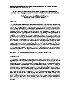
SHDSL (ITU-T G.991.2, [46]) and VDSL (ITU-T G.993.1, [47]) transmission technology with data rates up to 10 Mbps. Also designed for point-to-point links, EFM Fiber (EFMF) interfaces for single-mode fibers allow an increased data rate of up to 1 Gbps. EFM Passive Optical Network (EFMP) interfaces introduce passive optical networks (PON), which is a completely new concept in Ethernet. An Ethernet PON (EPON) is a full duplex single fiber network with point-to-multipoint topology and data rates up to 1 Gbps7 . As shown in figure 7, it consists of a central optical line termination (OLT) and several optical network units (ONU), which are connected by a passive splitter/combiner. Each ONU connects one or several customers to the network. Packets from OLT to the ONUs, i. e. in downstream direction, are transmitted by the OLT to the splitter/combiner, which broadcasts them to all ONUs irrespective of the packet’s destination. The ONUs filter the packet stream and forward only those for the respective receiver while all other packets are dropped. For this selection, the OLT assigns a logical link identifier (LLID) to each ONU and marks all packets with the LLID of the receiver ONU. Vice versa, i. e. in upstream direction, all packets are transmitted to the splitter/combiner, which forwards the combined signal of all ONUs without any processing to the OLT. Accordingly, ONUs never receive the signal transmitted by another ONU. B. Medium Access It is obvious that in downstream direction, the medium is dedicated to one sender, namely the OLT, whereas in upstream direction it is shared. Historically, Ethernet is well suited to deal with a shared medium. Nevertheless, Ethernet’s typical medium access scheme CSMA/CD is not applicable as sensing is not possible. Thus, to control the EPON, the multipoint control protocol (MPCP, [5]) has been introduced. The MPCP is implemented in the MAC control layer and centrally coordinates the medium access of the ONUs based on the time division multiple access (TDMA) principle. Besides, it allows to dynamically distribute the transmission capacity among the ONUs by adjusting the duration of the time slots. For this, the OLT signals each ONU the start time and duration of its next time slot at least every 50 ms. During this time slot the ONU may transmit user data and signal the current filling level of their transmission queues to the OLT. Based on this level information a scheduler in the OLT allocates further time slot to the ONUs. As the scheduler is not specified, many different scheduling strategies can be implemented (cf. [48]). C. Link level OAM The task of link level OAM is to allow a network operator to manage and monitor the path between two MAC layer entities, e. g. between the OLT and ONU. For this, the OAM sublayer has been defined as client of the MAC or MAC control layer with a slow protocol, i. e. a protocol with limited data rate [49]. 7 the
IEEE P802.3av task force is working towards 10 Gbps
10 (5) (2) (1) Pre LLID SFD DA SA
OLT
1
2 3 Upstream
1
Downstream
1 2
2
1
3
2 3 2
1
1
ONU
1 Splitter and Combiner
Variable length packets IEEE 802.3 format
Fig. 7.
2 3
ONU
2
2 3 3
ONU
1
2
End User 2
3
End User 3
2 2
End User 1
3
Downstream and upstream traffic flow of an EPON
It relies on in-band signaling and transmits dedicated OAM frames via the MAC and PHY that is also used for user data. Such OAM messages may be sent several times in order to increase the reliability in situations with high error rates. It must be noted that the entire system can be used with any PHY and is thus neither limited to the local-loop nor to access networks. Besides the discovery of the OAM capabilities of the neighboring nodes, there are three kinds of functions provided by link level OAM. First, data terminals can signal critical and non-critical events. While non-critical events are dedicated to the permanent supervision of error rates in defined time intervals (several symbols, frames, etc.), critical events are signaled if no bidirectional message exchange is possible. The most prominent critical event is a link fault, which is signaled if the receive path is broken. Second, for fault localization the remote loop back mode has been introduced. In this mode, the OAM sublayer reflects all received frames to the sender. This allows testing the MAC-to-MAC path. Third, as the lower layers in Ethernet only poorly inform their neighbors about errors, a variable retrieval mechanism is defined. This allows to read objects from the remote station’s management information base. V. I NDUSTRIAL E THERNET After the IEEE began to standardize Ethernet, different vendors (e. g. Siemens, [50]) adopted Ethernet for industrial applications. Today, the vendors mostly use the term industrial Ethernet for Ethernet-based solutions. In contrast to the Ethernet of corporate LANs, industrial Ethernet has to fulfill enhanced requirements such as time synchronization, (hard) real-time operation, and high availability. Furthermore, industrial Ethernet connectors and hardware have to meet ambient condition requirements of factory equipment such as electrical noise, vibration, temperature, and durability [51]. The driver was to reduce the steadily increasing costs and complexity as well as to connect a wide range of devices in the factory automation and control infrastructure. A further objective was to interconnect the factory and the office network for simple remote access to individual devices. Besides, Ethernet bandwidth and its further development promised to cover future needs [52], what it does to this day. In recent years, more and more devices have come with a built-in Ethernet interface. Since Ethernet has been adapted to fulfill industrial requirements, it has started to replace fieldbus technologies such as Profibus [53] and Sercos [54], which
are close to reaching their capacity limits. The trend of using Ethernet in industrial environments also affects related fields of application with similar requirements. Nowadays, Ethernet satisfies communication needs in many embedded networks, e. g. in marine applications and building automation. Traditionally, these have also been the domains of fieldbuses, which are gradually replaced by Ethernet. A. Networking requirements Industrial networks have to transmit information (e. g. temperature or position data) between sensors, actors, and controllers. In factory automation, we categorize networking components and technologies according to performance characteristics, exchanged information types, and cost. The performance characteristics comprise the number of attached devices, data rate, physical network size, response time, payload size, and frequency of data exchange. We thereby classify the networking components and technologies in hierarchical levels. Typical levels are the plant level, the control level, and the device level [55], [56]. The advantage of Ethernet is its potential to cover all levels as a single integrating networking technology. The plant level comprises an entire production facility and connects a large number of factory cells and machine process controllers. This level tolerates reaction times up to several hundred milliseconds [57]. The control level connects a moderate number of specialized computing devices such as machine control systems over a moderately large area. In this level, the reaction times have to be smaller than 10 ms [58]. The device level enables the communication between sensors and actuators and requires normally a response time smaller than 1 ms with a jitter of less than 1 µs [59] for motion control with high frequency and small payloads [57]. Figure 8 depicts these differences of performance characteristics. The levels also structure the information flow required for factory and process automation [58]. B. Real-time Ethernet Solutions Today, a number of different real-time Ethernet solutions supporting different classes of QoS exist. Due to the multitude of solutions and the history of their development, it is not possible to give a clear-cut definition of the term realtime Ethernet. One major criterion is whether a solution is compatible with IEEE 802.3 compliant devices or not. Decotignie [60] classifies industrial Ethernet solutions according to their degree of compatibility with commercial off-the-shelf
11 Latency ms
Response time sec
Transfer size MByte
Message frequency rare
< 1 ms
ms
Bit
often
Plant level Control level Device level
Fig. 8. Networking requirements and characteristics of the levels in an industrial environment [55], [56]
(COTS) Ethernet technology: (1) interoperable homogeneous, (2) interoperable heterogeneous, and (3) non-interoperable. All these solutions carry the generic label industrial Ethernet or real-time Ethernet, even though they describe different and mostly incompatible technologies [60]. 1) Interoperable, homogeneous solutions: Interoperable and homogeneous solutions build on IEEE 802 standards, as shown in figure 9, and thus are compatible with IEEE 802.3 compliant devices, i. e. devices implementing the following improvements are able to communicate with COTS Ethernet devices. The use of switches and full duplex links eliminates collisions. This makes QoS predictions easier and in turn enables the use of Ethernet as an industrial network for distributed real-time applications. As defined in the IEEE 802.1Q standard, Ethernet allows frame tagging that enables traffic prioritization and a separation of real-time and best effort traffic (which gets the lowest priority). Bridges can handle up to eight traffic classes, although in practice they only use four [60]. With respect to higher layers, two approaches exist. On the one hand, both real-time and best effort traffic can use the TCP/UDP/IP protocol suite. This solution allows transparent communication over network boundaries [59], but guarantees only relative QoS. The second option implements an additional real-time protocol stack, i. e. the real-time data bypasses the TCP/UDP/IP protocol stack and thus avoids potential delays introduced by these protocols [59]. An example of an interoperable, homogeneous solution is the Ethernet industrial protocol (EtherNet/IP, [61]). This solution uses tagged Ethernet frames and assigns real-time frames the highest priority [59]. Although the use of bridges and traffic prioritization avoids collisions, it does not make Ethernet deterministic. For example, if the buffer size inside a switch is too small to store simultaneously arriving frames temporarily, an overflow of the buffer and frame losses occur [60]. Therefore, the industry developed and adopted enhanced solutions. One such approach is the implementation of an additional traffic scheduler on top of Ethernet to regulate the traffic. It can take the task of a traffic smoother proposed by Kweon et al. [62], which is located between the transport layer and the data link layer, as shown in Figure 9, and smoothes data streams between these two layers. Its implementation requires enhancements of the protocol stack at the end systems. The MAC protocol, however, remains unchanged. Therefore, it runs on IEEE 802.3
compliant hardware. Such a traffic scheduler can be a traffic shaper or a token bucket. This leads to smooth traffic in which messages arrive at a constant rate and not in a bursty manner. A traffic regulator delays bursty traffic for longer periods and thus improves the network performance [60]. In recent years, several authors [57], [62]–[75] have suggested and analyzed the real-time behavior of these solutions, some of them making additional assumptions like limited network load. Others analyze the delay bounds by using the priority field in the Ethernet frame, where the real-time traffic is given the highest priority, like in EtherNet/IP, and the best effort the lowest priority. 2) Interoperable, heterogeneous solutions: The solutions discussed in this section are also able to communicate with IEEE 802.3 compliant devices. However, their key to guarantee real-time capabilities is the exclusive use of modified switches [60]. No other intermediate devices, hubs, switches, or routers are allowed. Otherwise, the communication falls back to the legacy best effort service of Ethernet, which is insufficient for real-time applications. An example of such a solution is EtheReal [76]. This solution provides bandwidth guarantees by connection-oriented operation. When a device wants to transmit real-time data, it tries to set up a connection via a reservation protocol. If enough resources are available, a switch forwards the connection request to the next hop on the path. Each switch repeats this process until the last switch is reached and the connection is established. The last switch confirms the reservation by sending a message back. This approach is similar to the resource reservation protocol (RSVP, [77]). Another more prominent example of an interoperable, heterogeneous solution is Profinet [50]. It differentiates several classes of communication services by means of synchronous time-division multiplexing: An isochronous real-time, a realtime, and a non real-time service. Each time slot allows the transmission of several Ethernet frames. A central entity manages the assignment of isochronous transmission capacity in the first time slot of a cycle. In the following slots, the realtime frames followed by the non real-time frames are transmitted. A special Profinet switch forwards the isochronous realtime frames without any interpretation [59]. In the following time slots, the switch changes to normal Ethernet operation and interprets the destination address to forward a frame to the corresponding port. 3) Non-Interoperable solutions: Applications with high timing requirements, e. g. motion control, usually base on noninteroperable solutions. Such solutions use an additional, deterministic MAC as depicted in figure 9 and can be implemented on COTS IEEE 802.3 compliant hardware. Decotignie [60] lists different types of deterministic MAC, which have been used over the last years. These types include TDMA, masterslave, token passing, slot reservation, and time packet release. Networks implementing such enhancements are isolated from regular Ethernet networks by bridges. All real-time guarantees are lost in presence of traffic from regular IEEE 802.3 devices due to the different MAC protocols. A representative example is the Ethernet for control automation technology
12
Interoperable solution
Non-interoperable solution
application real-time best effort data data
application real-time best effort data data
UDP
TCP IP
Fig. 9.
real-time protocol stack
UDP
TCP IP
real-time protocol stack
Scheduler
Non IEEE 802.3 compliant MAC
LLC 802.2
LLC 802.2
MAC 802.3
MAC 802.3
2 Mbps multi transmitter bus supporting up to 120 nodes. However, this protocol has not gained general acceptance, due to high complexity and development cost. Hence, another solution that follows the new trend of using COTS technology was proposed to reduce the development costs and facilitate the maintenance process. A commercial standard (ARINC 664, [83]) and a specific aircraft implementation known as avionics full duplex switched Ethernet (AFDX, [83]) have recently been developed to define the use of switched Ethernet in aircraft. This latter has been successfully integrated into new generation civil aircraft like the Airbus A380.
Real-time Ethernet solutions
A. Requirements (EtherCAT, [78]). It uses the Ethernet frame format in a ring topology [58]. A master generates an Ethernet frame with a slotted data field. Each device allocates a number of slots and removes or adds information there. This information can be I/O information as well as TCP/UDP/IP data. Due to the on-the-fly processing, EtherCAT reaches a cycle time of 30 µs [58]. If required, the EtherCAT protocol may be tunneled through IEEE 802.3 compliant or IP-based networks in UDP packets, however without real-time guarantees. C. Topology and Availability Unlike in the office environment, most devices in an industrial network include an embedded bridge, which results in three possible topologies: line, ring, and tree. In the first two cases, each embedded bridge has three ports, the device being connected to one of them. The other two bridge ports are used to connect to adjacent switches. R¨uping et al. analyze these topologies in [79] with respect to the transmission delay. They show that the tree topology performs best, the ring topology second, and the line topology worst. In addition, the tree topology requires a smaller number of switches. Industrial applications need highly reliable communication between several devices, not only between a client and a server as in the corporate LAN. Therefore, redundant links are deployed for resilience, e. g. in a ring topology. Less timecritical applications can cope with a higher recovery delay and the topology reconfiguration by (R)STP is sufficiently fast to recover from a failure. In contrast, (safety-critical) realtime applications require the parallel operation of redundant networks. Today, a number of redundancy methods to ensure a high availability exist. The International Electrotechnical Commission (IEC) is working on standards that define redundancy schemes suitable for industrial Ethernet networks. Kirrmann and Dzung [80] discuss redundancy requirements and classify redundancy methods. VI. AVIONICS E THERNET Over the last thirty years, the ARINC 429 [81] data bus has been widely used in various civil avionics applications. However, the increasing complexity of avionics systems is pushing this traditional data bus well beyond the limits of its bandwidth (100 kbps). In order to overcome these limitations, Boeing proposed the ARINC 629 [82] data bus. It offers a
Avionics requirements concern both technical aspects and cost. The former consist of performance, safety, scalability, maintainability, and environment requirements. First, performance requirements concern: 1) the applicative latencies that have a magnitude order of milliseconds and an allowed bounded jitter and have to respect deadline constraints; 2) the throughput that has to be at least 100 Mbps to guarantee the aircraft a viability of thirty years or more; 3) deterministic behavior where the system must be able to deliver correct information in a predictable manner. Second, safety requirements include: 1) reliability where a service continuity has to be guaranteed and mechanisms to detect, correct, or ignore errors have to be available; 2) integrity with a very low error rate; 3) availability that is often brought by redundant architectures; 4) security by supporting network domains with different security levels. Third, we find scalability and maintainability requirements where the system has to support easy addition, removal, and maintenance of any node on the network to be viable for future evolutions. Finally, environment requirements impose compatibility with aircraft conditions (electromagnetic interference, vibration, heat, etc.) on the network. Concerning cost requirements, a trade-off between the price and availability of network components and the deployment effort is required. Certainly, the use of a COTS technology has many advantages like increasing the number of vendors and thus reducing the component prices. However, the implications of a new network on the existing applications (avionics functions) have to be taken into account by adding mechanisms to guarantee compliance. We give an overview of the AFDX in section A. Section B surveys other works trying to extend the Ethernet’s implementation in military avionics context. B. AFDX standard The AFDX standard [83] defines protocol specifications (ARINC 664 part 7) for the data exchange between avionics subsystems. This protocol represents an analogy to the ARINC 429 bus thanks to the virtual link (VL) concept that gives a
13
0000
4
2 Virtual Link ID
Constant Field Destination Address (DA) 6 DA
6 SA
3 Constant Field
Domain ID
Location ID
Side ID 1
1
Interf. ID
00000
1
Network Equipment Interface ID ID ID
Source Address (SA) 2 T
20 IP Header
8 UDP Header
variable UDP Payload (min. 17, max. 1471 B) Avionics Subsystem Message
1
4
Seq. No.
FCS
Ethernet Header AFDX Frame Ethernet Frame
Fig. 10.
AFDX frame format
way to reserve a guaranteed bandwidth and provides a simple transition for existing avionics functions. The VL defines a logical unidirectional connection between one source and one or more destinations. Thus, it shows multicast characteristics with one end system representing the source of a given VL. 1) Functional description: The AFDX topology is a closed network topology and consists of interconnected switches and end systems. An end system is used to connect each avionics subsystem to the network, but it can also support multiple avionics subsystems where partitions are used to provide subsystem isolation within the same end system. Each end system has two direct bi-directional connections to two redundant switches to guarantee the system’s availability. A MAC address, as depicted in figure 10, identifies the end systems. The source address is a unicast address and represents a unique end system, whereas the destination address is a multicast address where the VL identifier is embedded. Each end system can send data to multiple VLs. Thus, like the partition mechanism used to isolate subsystems within an end system, a similar mechanism is needed to isolate VLs to prevent interference between them. Hence, for each VL, the transmission rate and the maximal frame size are limited and defined a priori. Each VL has two main parameters: •
•
The bandwidth allocation gap (BAG) that presents the minimal inter-arrival time between two frames sent on the VL. It ranges in powers of 2 from 1 ms to 128 ms; Lmax that is the largest Ethernet frame length transmitted on the virtual link.
All VLs generated by the same end system are controlled and scheduled by a VL scheduler inside each end system. This scheduler ensures that each VL respects its associated rate and length limitations and is responsible of multiplexing the different VLs. The management of the VLs by the end system is called traffic shaping. Each end system also integrates redundancy management to deal with the data received and transmitted on the redundant connections. The transmitting end system sends the same frame using two redundant paths to the same receiving end system. The receiving end systems choose the first valid frame. The switches used in AFDX implement static configuration tables to define the associated physical ports for each VL. When a message is received, it is routed to its destination port(s) based on the VL. Hence, the STP and the address
resolution protocol (ARP, RFC 826 [84]) mechanisms are not necessary and disabled. These switches work in store-andforward mode to check frame integrity and discard invalid frames. Furthermore, they ensure that each port sends correct VLs by means of policers. Frames that do not respect the associated VLs characteristics are discarded. 2) Extensions to IEEE 802.3 and 802.1D: The AFDX specification [83] defines compliance degrees with regard to Ethernet and IP standards and distinguishes two types of networks: compliant network and profiled network. Compliant networks apply standard specifications. They are used for noncritical applications. Profiled networks require some extensions to the Ethernet standard to support avionics requirements. They include two major extensions. • Extensions to 802.3 standard: The traffic is controlled inside each source by using the VL concept and traffic shaping technique to guarantee the characteristics of each generated flow. For each VL, a sequence number is added to the Ethernet frame (1 byte field that occurs just before the FCS field). This is mainly used within each end system for redundant networks and for the integrity checking of received frames on the same VL to control the arrival order. • Extensions to 802.1D standard: AFDX switches are aware of VL characteristics and include policers that enforce the VL traffic contracts. Violating frames are rejected. Extensions to standards and conception choices, like a statically defined topology and VLs, enable the deterministic behavior of the network [85], [86]. C. Extension to Military Avionics The integration of the AFDX standard in the Airbus A380 was a great success in civil avionics. Therefore, full duplex switched Ethernet became attractive for next generation military aircraft. It is worth to note that AFDX could not be used for military applications. In fact, the requirements of communication protocols are distinct in civil and military applications. AFDX has been defined to provide traffic isolation and bandwidth guarantee along with a guaranteed latency to all traffic flows, whereas military applications need several service classes in severe military environments where bandwidth may not be the primary design concern.
14
Limitations of current military avionics networks motivate the integration of switched Ethernet in military applications. With the increasing complexity of interconnected subsystems and the expansion of exchanged data quantities, the current networks no longer meet the emerging requirements of new military applications in terms of bandwidth and latency. Therefore, in order to fulfill these increasing needs, two communication networks based upon micro-segmented Ethernet were proposed to replace the current military network [87]. The first proposal uses a distributed communication scheme where devices can emit data simultaneously [88]. This solution improves global throughput and the system’s flexibility. However, the existing subsystems are implemented to work in a centralized communication scheme, due to the widely used command/response data bus MIL STD 1553B [89]. Therefore, adapting all existing applications for distributed communication would be expensive. In order to avoid this process, the second proposal keeps the current centralized communication scheme and deploys an optimized master/multi-slave transmission control. However, this profiled network seems more constrained than the one with distributed communication scheme since a higher data rate is necessary to satisfy all realtime constraints [87]. The selection of the appropriate network requires a trade-off between real-time guarantees and cost. The standardization of these proposals for military avionics applications is an open issue. VII. AUTOMOTIVE E THERNET In recent years, the importance of automotive electronic systems has grown rapidly as original equipment manufacturers (OEMs) keep adding new functions and applications. Today, electronic systems and software directly or indirectly enable most innovations. For example, the electronic stability control (ESC) improves safety by controlling individual brakes automatically. At the beginning of automotive electronic systems, the OEMs implemented each application on a stand-alone electronic control unit (ECU), which is a subsystem composed of a micro-controller and a set of sensors and actuators [90]. Later, the ECUs exchanged data through point-to-point links. With an increasing number of ECUs and distributed applications, this approach became insufficient and the OEMs introduced networks with multiplexed communication. Later on, the OEMs grouped ECUs with similar characteristics and requirements together in one domain. For example, the infotainment domain groups ECUs which offer information and entertainment services and applications such as DVD player, navigation system, and remote diagnostic. Further typical in-vehicle domains are chassis, powertrain, body, and comfort. The different domains have separate communication systems, which are connected via gateways. Today, an upperclass passenger car contains up to 70 ECUs with several hundred software-enabled functions distributed over different network technologies. The different in-vehicle network technologies came from the diversity of requirements. These requirements are unique in their combination of innovation and cost-driven massmarket characteristics with high demands on data rate, safety,
reliability, usability, and a wide spectrum of other quality properties [91]. The installation during manufacturing has to be as simple as possible, too, and the components have to be automotive qualified concerning temperature compatibility, electromagnetic compatibility, etc. Currently, the most commonly deployed in-vehicle network technologies are LIN [92], CAN [93], and MOST [94]. These network technologies are automotive-specific. Consequently, further developments, enhancements, and standardization are OEM- or supplier-driven. These network technologies have become inflexible, complex, and costly, and some of them are reaching their capacity limits [95]. A. Ethernet’s drivers Increasing the offered bandwidth of the applied technologies such as CAN and MOST would lead to extra costs. Due to the cost sensitivity of the automotive industry, the OEMs and suppliers keep an eye on other low-cost network technologies available, which can also fulfill requirements of an in-vehicle network technology. Ethernet is an eligible candidate and becomes more and more attractive [95]–[98]. The automotive industry aims at reducing the development times. Using standardized technologies and mass-market components instead of developing automotive-specific technologies achieves this objective. Ethernet is a flexible technology that is suitable for both quickly changing platforms and different car series. Ethernet enables a simpler development process thanks to the reuse of components. Many solutions that integrate Ethernet and higher-layer protocols such as TCP/IP on a single chip are already available. In addition, Ethernet could be a technology that fits for nearly all above-mentioned domains. Thus, this would avoid the parallel and independent development of different technologies. Therefore, the exclusive use of Ethernet reduces cost and complexity. With low-cost bridges, the interconnection of Ethernet subnetworks is also simple. Another solution is to separate different domains by VLANs. Consequently, there is no need for complex gateways. Reaching more than 30 years (including development), the life cycle of a car series is much longer compared to consumer electronic. In case consumers want to integrate their electronic devices, the in-vehicle communication systems have to be scalable over this time. There is a relation between innovation cycles of customer electronic devices such as personal digital assistant (PDA), semiconductor technology, and cars’ product lifespan. Processors and chips, or backward compatible components, have to be available during cars’ lifetime. Next generation in-vehicle communication systems have to be robust with respect to possible future evolutions. The history of Ethernet has proven that it is a sustainable technology, which has not yet reached its limits and can fulfill upcoming requirements. In a car, electromagnetic interference (EMI) plays an important role. The installation of polymer optical fiber (POF) is simple and avoids EMI. In addition, POFs are a cost effective solution and will support up to 1 Gbps in the future. Some suppliers already work on Ethernet over POF solutions. For example, Infineon offers full duplex POF transceivers and POF media converters [99].
15 In-vehicle domains
Infotainment domain
Application
Delay
Payload size
100 ms
MByte
Streaming
Audio/Video Bridging Ethernet
Interactive
Control domains
Fig. 11. domains
Hard real-time (safety)
Similar network characteristics and requirements
10 ms
Bit
Industrial Ethernet (Control and Device level)
Networking requirements and characteristics of the in-vehicle
B. Networking requirements So far, we discussed non-functional requirements. However, Ethernet has to fulfill networking QoS requirements, too. In [95], Rahmani et al. categorize in-vehicle traffic into four classes based on their QoS requirements: Hard real-time control data, real-time audio and video data, multimedia data, and best effort data. The hard real-time control data contains sensor information from the control domains. Typically, this information is only a few byte long and the data rate is low. The maximum end-to-end delay of packet transmission, derived from CAN cycle time, amounts to 10 ms. Safety applications like ESC have such hard real-time requirements. In an isolated, closed domain with time-triggered, deterministic applications, the worst-case end-to-end delay and jitter is calculable. Typically, control domains with safety applications are isolated and an extra scheduler controls the traffic coming from other devices outside of the domain. As shown in figure 11, the control domain has similar requirements and communication characteristics as the control and device level in industrial communication systems discussed in section V. Therefore, it offers opportunity to adopt existing industrial Ethernet solutions. In the infotainment domain, we have to distinguish between interactive and streaming applications as depicted in figure 11. Streaming applications basically have strong requirements concerning the delay and jitter. However, the data streams allow buffering on the receiver side and thus end-to-end delays of up to 100 ms are tolerable. In contrast, it is not possible to buffer the data stream of an interactive application, e. g. of a rear view camera. Thus, the maximum end-to-end delay should be less than 45 ms. Both categories are time-sensitive, have a variable data rate, and require a packet loss of less than 0.1 %. The multimedia domain has similar requirements and communication characteristics as in-house multimedia networks. Thus, solutions discussed in section VIII provide a good basis for developing an Ethernet in-vehicle infotainment communication system. Ethernet’s flexible frame length supports both the transmission of control data of only a few bytes at a high frequency, and multimedia streams with large frames sizes. Therefore, it fits control and streaming applications. The dimensioning of switches’ and NICs’ buffers guarantee a low packet loss rate. Thanks to its high data rates, Ethernet satisfies the high bandwidth demands of upcoming applications, especially in the infotainment domain where HD-Video and Dolby-surround
will become essential. In the future, customers may connect their personal electronic devices, which leads to an additional amount of traffic. In this case, the safety critical domains have to be protected against unknown traffic, which would cause unknown delay and jitter. One approach to prevent this uses physically separated domains connected by gateways. A quite different approach is to configure VLANs. For this purpose, VLANs partition a single physical communication system and the Ethernet frame tags are used for traffic prioritization. In one such VLAN, which presents a separated domain, customers can integrate their devices without affecting the existing applications. This approach is similar to the VL concept in the avionics field discussed in section VI. C. Topology In a car, weight and packaging, and therewith the topology, play an important role. The topology minimize the total cable length and fulfill installation demands. There are several approaches to design an Ethernet in-vehicle communication system without redundant paths. Typical Ethernet networks use tree topologies. Theoretically, this solution is applicable, too. However, deploying for example one central switch located anywhere inside the car would lead to cable bundles. The use of more than one switch avoids such cable bundles. We thereby have two possibilities: (1) the switches are located anywhere inside the car or (2) the switches are embedded within the devices. In the former case, additional cabling for the power supply of the switches is needed. The latter solution leads to a line or ring topology. In section V-C, we discuss the performance of different solutions. Rahmani et al. compare several in-vehicle network topologies, e. g. a unidirectional ring, by their QoS performance and production cost in [95]. D. Outlook Automotive Ethernet is not a standardized term or technology. It is rather used for an ongoing discussion whether Ethernet has the potential for an in-vehicle communication system. A first step could be the deployment of Ethernet in the multimedia domain instead of MOST. Due to the large production volume, cost per piece plays an important role for the automotive industry. If the cost between hubs and switches differs significantly, hubs might be deployed. This would mean the rebirth of collision domains and the CSMA/CD MAC protocol. In such a solution, the unfairness between nodes to access the shared medium and unpredictable collisions will lead to an unpredictable timing behavior. However, approaches which fix this problem and enforce real-time behavior over a shared Ethernet medium already exist [100]–[102]. In summary, the decision to bring Ethernet into cars is motivated by possible cost reductions with respect to development, manufacturing, and maintenance as well as the satisfaction of increased application demands. In the automotive industry, we find similar, challenging networking problems as in other fields of application. Thus, we can adopt solutions from these fields. We can bring ideas from industrial Ethernet (section V) and
16
avionics Ethernet (section VI) into the car and improve them. Home entertainment (AVB) networks (section VIII) also have a lot in common with the infotainment domain in a car. VIII. AUDIO AND V IDEO B RIDGING E THERNET This section presents the intentions of the IEEE audio/video bridging task group (AVB) [103] and the enhancements of the IEEE 802 standards they are developing. For a few years, the market of home multimedia networks has been growing. Consumers want to access multimedia content and resources stored anywhere in the house using their computers and entertainment devices. Though not widely adopted for streaming multimedia applications with real-time requirements yet, Ethernet has the potential of serving both data and multimedia networking needs and thus is suited for the backbone of an integrated digital home network. Hence, there is a growing need for an Ethernet network able to distribute high quality digital audio and video reliably [104]. A. Enhancements The current IEEE 802 standards do not provide robust QoS guarantees concerning latency and bandwidth. Therefore, the IEEE founded the 802.1 AVB task group to specify protocols and mechanism supporting services for streaming multimedia applications, which have time-synchronized, realtime requirements, and need high data rates at low latencies. AVB Ethernet will guarantee an isochronous service with less than 2 ms end-to-end latency and only 250 µs through one bridge. This maximum end-to-end latency is based on a total trip budget of 10–15 ms for lip to ear synchronization. The maximum number of bridges is limited to 7 [105]. The isochronous service is only supported over 100 Mbps or faster full duplex links. Today, Ethernet does not feature a mechanism to guarantee a certain bandwidth to an application. However, this is essential for multimedia streaming applications, which need deterministically low latency and low jitter. Therefore, the upcoming IEEE amendment 802.1Qat [106] specifies a stream reservation protocol (SRP). Besides the protocol specification, the amendment will comprise procedures and managed objects to be used by existing higher-layer mechanisms that allow resource reservation for specific traffic streams. The SRP reserves network resources, i. e. bandwidth shares, if they are available along the entire path from the talker (source) to one or more listeners (destinations). The procedure is similar to the one described in section V-B.2. A listener sends a join request control frame to the talker. This frame contains information including the amount of required bandwidth and the channel number. If the resources are available, the talker receives the request and returns a join response message. Otherwise, the intermediate switches mark the message as resource not available, but still forward it to the talker. This admission control scheme enables connection-oriented bandwidth reservation by end-to-end management. In addition, a bridge has to obey frame-forwarding rules to provide guarantees for time-sensitive multimedia streams, i. e. bounded latency and delivery variation. The IEEE amendment
802.1Qav [107] specifies forwarding and queuing enhancements for bridges, including per priority ingress metering, priority regeneration, and timing-aware queue draining algorithms. Besides a strict priority transmission selection scheme, the bridges have to support a credit-shaper algorithm. Again, we see similarities to the industrial solutions deploying additional schedulers. A uniform time basis is essential for meeting the jitter, wander, and time synchronization requirements of timesensitive streaming applications, especially for applications involving multiple streams delivered to multiple endpoints. The upcoming IEEE standard 802.1AS [108] therefore specifies timing and synchronizing services on the data link layer. This standard includes both time-stamping and media coordination services [105] with a timing difference of less than 1 µs between devices. For this purpose, the root of the clock spanning tree distributes the accurate time throughout the AVB domain by means of time measurements between adjacent time-aware devices. However, Ethernet components require modifications in order to provide these features. The MAC layer needs an accurate frame timer and separated queues to provide an additional traffic class. The driver firmware and bridges need an update to support admission control and bandwidth allocation mechanisms. Furthermore, a realtime clock module and a time synchronization method are necessary. In summary, the new IEEE standard [108] and amendments [106], [107] enable the legacy Ethernet technology to provide an isochronous and deterministic low-latency service for multimedia streaming applications. The proposed standards require small changes to Ethernet’s MAC and some more significant changes to the 802.1D bridges. These enhancements are similar to some solutions in the industrial field as discussed in section V. B. Interworking Since multimedia data is transported in normal, tagged Ethernet frames, AVB enabled devices can interoperate with IEEE 802.3 compliant Ethernet hardware. However, all QoS guarantees are limited to the AVB domain as we illustrate in figure 12. Just like for the interoperable, heterogeneous industrial solutions, the key to guarantee QoS is the exclusive use of AVB compliant bridges and devices – along with full duplex links. Outside of the AVB domain (grayed out in figure 12), we have no QoS guarantees. If there are any half duplex links, hubs, legacy switches, or legacy devices, we leave the AVB domain and fall back to the legacy best effort service of Ethernet, which is insufficient for streaming applications. An AVB domain can only contain a limited number of bridges, but may have any physical structure. The STP assures a loop-free logical topology. IX. C OMPARISON The deployment of some Ethernet technology is common to all fields of application. Since these fields show huge differences in their requirements and constraints, the according Ethernet variants also do. This section compares the different
17
Corporate LAN IEEE
Transport Carrier Grade (PBB-TE) IEEE, ITU-T, MEF
Data rate
up to 10 Gbps, 100 Gbps1
up to 10 Gbps, 100 Gbps1
Physical topology
mesh
mesh
Logical topology MAC protocol
tree dedicated channel
mesh dedicated channel
Switching identifier
MAC addresses
path identifier (internal MAC + B-VID)
Control philosophy
plug-n-play or fully managed
central management and resource provisioning
Fault management
STP or manual interaction
OAM and hard guarantee by protection switching (50 ms restoration time)
Consortia
1 2
Networks First Mile
Industrial1
IEEE, MEF (previous: EFMA) 2 Mbps– 1 Gbps, 10 Gbps1 point-to-point, tree point-to-point dedicated channel, PON: TDMA
MAC addresses, PON: additional logical link ID central management and resource provisioning
link level OAM, outage detection and recovery, but no physical disjoint paths
Embedded Networks Avionics Automotive2
IEEE, IEC, ISO
ARINC 664
100 Mbps (predominant), 1 Gbps line, ring, tree
AVB IEEE
100 Mbps
consortium of OEMs and suppliers 100 Mbps
mesh
line, ring, tree
mesh
tree or mesh dedicated channel and additional MAC protocols2 MAC addresses
mesh dedicated channel
tree or mesh dedicated channel
tree dedicated channel
VL identifier
MAC addresses
MAC addresses
statically configured, (predominantly) isolated, and autonomous network manual interaction and proprietary solutions; partly redundant networks
statically configured and autonomous network (FDBs and VLs predefined) two redundant networks
statically configured, (predominantly) isolated, and autonomous network restoration / configuration only in workshops
plug-n-play and automatically configured
≥ 100 Mbps
STP
IEEE 802.3 compliant solutions Work in progress; it depends on the final solution (see different solutions in section V-B) TABLE I F UNDAMENTALS
AVB dev
dev
AVB domain AVB Legacy switch
AVB dev
AVB AP
AVB
AVB compatible access point
AVB dev
dev
AVB dev
AVB dev
AVB compatible switch
Does not work on half duplex links
Hub
Fig. 12.
Streaming QoS only within the AVB domain
AVB compatible device
AVB link Legacy Link
Topology and interworking of an AVB domain [105]
Ethernet technologies and highlights their differences and similarities. Telecom operators selling transport services to their customers run transport networks like carrier grade Ethernet and EFM. They have to comply with stringent service guarantees, particularly with respect to availability and bandwidth. OAM mechanisms are therefore essential. Deployed network tech-
nologies do not only have to scale to huge network sizes, but also have to provide means to cope with an ever-increasing bandwidth demand. Traffic engineering allows for an efficient utilization of installed resources in order to assure the return on investment. The applications and the number of nodes dictate the requirements for embedded networks. They need to support real-time communication for time-critical applications like factories, aircraft, and cars. Such networks are mostly closed, i. e. all occurring traffic is predictable (or shaped). They can therefore be dimensioned to fulfill safety requirements like timeliness. With respect to requirements and characteristics, a home multimedia network is a mixture of a SOHO and an embedded network. Like the latter, it faces QoS requirements such as deterministic service and low, bounded delays. However, it supports self-configuration and plug-and-play style attachment and removal of devices, as an Ethernet LAN does. However, the number of bridges in an AVB domain is limited. Following this classification, we assess and compare the characteristics and provided services of the Ethernet variants. We thereby focus on fundamentals and network QoS capabilities depicted in table I and table II, respectively.
18
A. Fundamentals The fundamentals describe specific characteristics of the different Ethernet variants. Following the rows of table I, we will outline the most important ones including data rate, topology, and control mechanisms. The IEEE plays a major role in the standardization of almost all extensions to Ethernet. In addition, further consortia, namely the ITU-T, MEF, ISO, IEC, and ARINC 664, published specific enhancements to the IEEE 802 standards. In the automotive sector, the ongoing discussion about the deployment of Ethernet is mostly driven by OEMs and suppliers. The data rate defines the transmission capacity of one link. Transport network applications are driving the development towards ever-higher data rates, currently 100 Gbps, since new applications and a growing number of users increase the bandwidth demand. The extension of the transmission capacity per physical link, i. e. fiber, is preferred to the installation of more fibers, since such works in the field are very expensive. For embedded networks, the situation is different. Data rates of 100 Mbps are mostly sufficient for their real-time control applications. Major design criteria include the robustness to environmental conditions like EMI, vibration, and heat. AVB networks may support various data rates, though the bandwidth demand of multimedia streaming applications imposes a lower bound of 100 Mbps. Concerning network topology, we have to distinguish between physical set-up and logical structure. In the majority of application fields, the physical topology is some kind of mesh, potentially ranging from tree to fully meshed structures. Some embedded networks, however, restrict permitted meshes to simple ring structures, and EFM is limited to tree topologies due to its deployment at the network’s edge. The logical topology often differs from the physical one, most prominently when the STP creates a loop-free structure by deactivating links, e. g. in LANs and AVB networks. In PBB-TE carrier networks, in contrast, both topologies are generally meshes, since traffic-engineered paths are insensitive to potential forwarding loops. While EFM only supports logical point-to-point links to connect individual subscribers, a potentially meshed logical topology is statically configured in embedded networks. If loops exist, the forwarding behavior of bridges, i. e. their FDB entries, needs to be defined statically as well. The Ethernet variants also differ in the network operation with respect to medium access control, switching identifiers, and network control. Dedicated channels, i. e. full duplex links and switches, are common to almost all application fields. Thus, Ethernet’s initial CSMA/CD mechanism is no longer in use. Even EFM, the only variant still using a shared medium, relies on a slotted TDMA scheme instead of CSMA/CD. The frame forwarding decision bases in general on the MAC address. When tagged frames are used, this address may show per-VLAN significance if the VLAN tag is also taken into account. This particularly applies to PBB-TE, where the BVID serves to distinguish several paths to the same destination. In avionic networks, the destination address field also serves as a switching identifier, but does not contain a normal MAC address. Instead, it features a VL identifier, which is basically
a multicast address. The classical control mechanisms of Ethernet like STP and MAC address learning, which are the basis of its plug-nplay style self-configuration, are only retained in LAN and AVB networks. In corporate LANs, they can provide interfaces for network management, e. g. to influence the spanning tree. In transport networks, operators do not rely on distributed control protocols. They centralize network control and explicitly assign resources to possibly dynamic traffic flows. OAM features thereby provide feedback on the state of the network. Conversely, embedded networks are isolated, thus need to function autonomously, without external control. However, the traffic circulating in such closed networks is generally known in advance, giving way to static configuration. If an embedded network is interconnected with, e. g. an office LAN, traffic shapers and policers are applied to restrict the unforeseen traffic. Fault management describes mechanisms and protocols to detect and recover from failures. Ethernet’s classical mechanism, the reconfiguration of the spanning tree, is still active in LAN and AVB networks. Carrier networks facing more stringent availability requirements deploy OAM mechanisms to detect and localize failures. Affected connections are then switched to a pre-established backup path. EFM networks allow for failure detection by link-level OAM, but do not support automated recovery. Most embedded networks in the industrial and automotive fields do not support fault management features, i. e. failures need to be resolved by manual intervention. In contrast, a redundant structure increases the resilience of avionic networks as well as of some highly safetycritical industrial applications. B. Network QoS Capabilities In this section, we discuss the network QoS capabilities of the Ethernet versions for different fields of application as presented in table II. We thereby focus on bandwidth as well as real-time metrics like latency and jitter, and evoke the mechanisms allowing for these guarantees. The table row labeled bandwidth indicates the network’s ability to provide guaranteed transmission capacities for individual data flows or traffic classes. Corporate networks only allow the assignment of bandwidth shares to different traffic classes, i. e. a relative guarantee. In embedded and AVB networks, in contrast, deterministic guarantees are enabled. The same applies to centrally managed transport networks, where transmission resources are reserved for traffic flows. However, if operators exploit traffic fluctuations for multiplexing gains, only statistical guarantees are feasible. The latency is the time needed to transmit an Ethernet frame from the source to the destination node. It comprises the processing delays in the source and destination nodes, the processing and queuing delays in all intermediate nodes, and the propagation delay between all these nodes. Networks exposed to uncoordinated sources of unknown traffic like LAN and EFM networks are unable to provide timing guarantees. Due to service contracts and traffic shaping at their edge, carrier networks allow for statistical guarantees. Embedded and
19
Transport Networks Carrier Grade First Mile (PBB-TE) hard or hard guarantee statistical guarantee
Bandwidth
Corporate LAN relative
Latency
no guarantee
statistical guarantee
Jitter
no guarantee
Mechanisms
traffic classes (802.1D) and VLANs
1 2
Industrial1
Embedded Networks Avionics Automotive2
hard or statistical guarantee
hard guarantee
no guarantee
hard or statistical guarantee
guaranteed
statistical guarantee
no guarantee
hard or statistical guarantee
guaranteed bounded jitter
resource reservation and traffic engineering
resource reservation
traffic schedulers, additional MAC protocols, and resource reservation
VL concept, policers
similar to industrial and/or AVB Ethernet similar to industrial and/or AVB Ethernet similar to industrial and/or AVB Ethernet similar to industrial and/or AVB Ethernet
AVB hard guarantee
hard guarantee (end-to-end 2 ms) low jitter
traffic classes (802.1D) and resource reservation (SRP)
IEEE 802.3 compliant solutions Work in progress; it depends on the final solution (see different solutions in section V-B) TABLE II N ETWORK Q O S CAPABILITIES
AVB networks designed for real-time applications implement mechanisms to deterministically bound the latency. The jitter is the variation of the end-to-end latency, i. e. the deviation of the inter-arrival times from the respective inter-departure times. It is therefore closely related to the latency, and guaranteed jitter bounds coincide with guaranteed latencies. The mechanisms providing these guarantees vary between application fields. Resource reservation and some form of limitation of the incoming traffic, however, are fundamental for any hard guarantee. Lacking such mechanisms, corporate LANs only provide relative guarantees based on traffic classes. Also based on VLANs and traffic classes, AVB Ethernet introduces an additional stream reservation protocol in order to give deterministic guarantees. In carrier networks, resource reservation is supported by traffic engineering and shapers enforcing service contracts limit the traffic. Embedded networks supporting safety-critical real-time applications use schedulers, shapers, and policers along with resource reservation protocols. Resource reservation in avionic networks is finally achieved by the VL concept. X. S UMMARY Starting as a local network technology, Ethernet diffused in a large number of fields of application, including transport, access, industrial, automotive, avionics and home entertainment networks. All these networks claim to rely on Ethernet technology. We surveyed the Ethernet technology of each of these application fields and compared the resulting Ethernet variants. We classified the fields of application of Ethernet in three major categories: (1) the operated and managed networks of carriers in the core and access part of a public or private
network; (2) the embedded networks in the manufacturing environment, in aircraft, and in cars; (3) the home entertainment (AVB) networks residing between LAN and category two. In each of these fields of application, Ethernet has adapted (or is on the way to adapt) to specific requirements. This adaptation process included changes in most ISO/OSI layers and additional extensions to the original IEEE 802 standards family. We identified the main changes to Ethernet in the following fields: OAM support and QoS capabilities, switching principle, and frame format. Besides, vendor specific solutions exist. Consequently, a unique definition of the term Ethernet is not possible anymore. The use of some frame structure being the only similarity in all fields of application, each implementation represents some kind of Ethernet technology. More than 30 years after the birth of Ethernet, only two attributes remain common to all technologies: one is framing and the other is the name – Ethernet. ACKNOWLEDGMENT The authors would like to thank Christian M¨uller, Rainer Blind, and Martin Neubauer for fruitful discussions. Special thanks also go to the reviewers who helped to improve the paper. The work presented in this paper was partly funded within the 100GET project 100G ARP by the German Bundesministerium f¨ur Bildung und Forschung under contract No. 01BP0768. R EFERENCES [1] C. E. Spurgeon, Ethernet: The Definitive Guide. O’Reilly Media, February 2000, vol. 1. [2] F. Gebali, Analysis of Computer and Communication Networks. Springer Publishing Company, Incorporated, 2008. [3] R. M. Metcalfe and D. R. Boggs, “Ethernet: Distributed packet switching for local computer networks,” XEROX Palo Alto Research Center, 3333 Coyote Hill Road, Palo Alto, California, USA, Tech. Rep., 1975.
20
[4] R. M. Metcalfe, D. R. Boggs, C. P. Thacker, and B. W. Lampson, “Multipoint data communication system with collision detection,” United States Patent 4063220, December 1977. [5] IEEE Computer Society, “802.3: IEEE Standard for Local and Metropolitan Area Networks–Carrier sense multiple access with collision detection (CSMA/CD) access method and physical layer specifications,” 2005. [6] ——, “802.5: IEEE Standard for Local and Metropolitan Area Networks–Specific requirements, Part 5: Token ring access method and Physical Layer specifications,” May 1998. [7] ——, “P802.3ba Draft Standard for Local and Metropolitan Area Networks–Carrier Sense Multiple Access with Collision Detection (CSMA/CD) Access Method and Physical Layer Specifications Amendment: Media Access Control Parameters, Physical Layers and Management Parameters for 40 Gb/s and 100 Gb/s Operation,” 2008. [8] ——, “802.11: IEEE Standards for Local and Metropolitan Area Networks–Wireless LAN Medium Access Control (MAC) and Physical Layer (PHY) Specifications,” 2003. [9] ——, “802.2: IEEE Standard for Local and Metropolitan Area Networks–Logical Link Control,” 1998. [10] ——, “802.1D: IEEE Standard for Local and Metropolitan Area Networks–Media Access Control (MAC) Bridges,” 2004. [11] Internet Assigned Numbers Authority (IANA), “IANA Ethernet numbers assignment,” August 2008. [Online]. Available: http://www.iana.org/assignments/ethernet-numbers [12] L. A. Chappell, Novell’s Guide to LAN/WAN Analysis. Foster City, CA, USA: IDG Books Worldwide, Inc., 1998. [13] IEEE Computer Society, “802.1Q: IEEE Standard for Local and Metropolitan Area Networks–Virtual Bridged Local Area Networks,” 2005. [14] G. Donahue, Network Warrior. O’Reilly Media, Inc., 2007. [15] R. Seifert and J. Edwards, The All-New Switch Book: The Complete Guide to LAN Switching Technology. Wiley Publishing, 2008. [16] O. Feuser and A. Wenzel, “On the effects of the IEEE 802.3x flow control in full-duplex Ethernet LANs,” Local Computer Networks, 1999. LCN ’99. Conference on, pp. 160–161, October 1999. [17] W. Takafumi, N. Masahiro, T. Hiroyasu, T. Otsuka, and M. Koibuchi, “Impact of topology and link aggregation on a PC cluster with Ethernet,” Cluster Computing, 2008 IEEE International Conference on, pp. 280–285, October 2008. [18] N. Olifer and V. Olifer, Computer Networks: Principles, Technologies and Protocols for Network Design. Wiley, 2006. [19] IEEE Computer Society, “802.1X: IEEE Standard for Local and Metropolitan Area Networks–Port-Based Network Access Control ,” Oct. 2001. [20] B. Aboba, L. Blunk, J. Vollbrecht, J. Carlson, and H. Levkowetz, “Extensible Authentication Protocol (EAP),” IETF, RFC 3748, June 2004. [21] J. Geier, Implementing 802.1X Security Solutions for Wired and Wireless Networks. Wiley, 2008. [22] E. L. Brown, 802.1X Port-Based Authentication. Boston, MA, USA: Auerbach Publications, 2006. [23] E. Rosen, A. Viswanathan, and R. Callon, “Multiprotocol Label Switching Architecture,” IETF, RFC 3031, Jan. 2001. [24] ITU, “Rec. G.8110.1/Y.1370.1 : Architecture of Transport MPLS (TMPLS) layer network,” International Telecommunication Union, ITUT, Nov. 2006. [25] B. Niven-Jenkins, D. Brungard, M. Betts, N. Sprecher, and S. Ueno, “MPLS-TP Requirements,” IETF, Internet Draft, Feb. 2009. [Online]. Available: http://tools.ietf.org/id/draft-ietf-mpls-tp-requirements-04.txt [26] MEF, “MEF Technical Specification 6.1: Ethernet Services Definition – Phase 2,” The Metro Ethernet Forum, April 2008. [27] ——, “MEF Technical Specification 10.1: Ethernet Services Attributes Phase 2,” The Metro Ethernet Forum, Nov. 2006. [28] ITU, “Rec. G.8011/Y.1307: Ethernet over Transport - Ethernet services framework,” International Telecommunication Union, ITU-T, Aug. 2004. [29] ——, “Rec. G.8011.1/Y.1307.1: Ethernet private line service,” International Telecommunication Union, ITU-T, Aug. 2004. [30] ——, “Rec. G.8011.2/Y.1307.2: Ethernet virtual private line service,” International Telecommunication Union, ITU-T, Sept. 2005. [31] ——, “Rec. G.707/Y.1322: Network node interface for the synchronous digital hierarchy (SDH),” International Telecommunication Union, ITU-T, Dec. 2003. [32] ——, “Rec. G.783: Characteristics of synchronous digital hierarchy (SDH) equipment functional blocks,” International Telecommunication Union, ITU-T, Mar. 2006.
[33] ——, “Rec. G.803 : Architecture of transport networks based on the synchronous digital hierarchy (SDH),” International Telecommunication Union, ITU-T, Mar. 2000. [34] ——, “Rec. G.709/Y.1331: Interfaces for the Optical Transport Network (OTN),” International Telecommunication Union, ITU-T, Mar. 2003. [35] ——, “Rec. G.872: Architecture of optical transport networks,” International Telecommunication Union, ITU-T, 2001. [36] TPACK, “PBB-TE, PBT - Carrier Grade Ethernet Transport,” TPACK, Tech. Rep., 2007. [Online]. Available: www.tpack.com [37] IEEE Computer Society, “802.1ad: IEEE Standard for Local and Metropolitan Area Networks–Virtual Bridged Local Area Networks, Amendment 4: Provider Bridges,” May 2006. [38] ——, “802.1ah: Draft Standard for Local and Metropolitan Area Networks–Virtual Bridged Local Area Networks, Amendment 6: Provider Backbone Bridges,” Nov. 2007. [39] ——, “802.1Qay: Draft Standard for Local and Metropolitan Area Networks–Virtual Bridged Local Area Networks, Amendment: Provider Backbone Bridge–Traffic Engineering,” Dec. 2007. [40] L. Fang, R. Zhang, and M. Taylor, “The evolution of carrier ethernet services-requirements and deployment case studies [next-generation carrier ethernet],” IEEE Communications Magazine, vol. 46, no. 3, pp. 69–76, 2008. [41] IEEE Computer Society, “802.1ag: IEEE Standard for Local and Metropolitan Area Networks–Virtual Bridged Local Area Networks, Amendment 5: Connectivity Fault Management,” Dec. 2007. [42] ITU, “Rec. Y.1731: OAM functions and mechanisms for Ethernet based networks,” International Telecommunication Union, ITU-T, May 2006. [43] ——, “Rec. G.807/Y.1302: Requirements for automatic switched transport networks (ASTN),” International Telecommunication Union, ITUT, 2001, wITHDRAWN. [44] E. Mannie and Ed., “Generalized Multi-Protocol Label Switching (GMPLS) Architecture,” IETF, RFC 3945, Oct. 2004. [45] D. Fedyk, L. Berger, and L. Andersson, “GMPLS Ethernet Label Switching Architecture and Framework,” IETF, Internet Draft, Oct. 2008. [Online]. Available: http://tools.ietf.org/id/draft-ietf-ccampgmpls-ethernet-arch-03.txt [46] ITU, “Rec. G.991.2: Single-pair high-speed digital subscriber line (SHDSL) transceivers,” International Telecommunication Union, ITUT, Dec. 2003. [47] ——, “Rec. G.993.1: Very high speed digital subscriber line transceivers,” International Telecommunication Union, ITU-T, June 2004. [48] M. P. McGarry, M. Reisslein, and M. Maier, “Ethernet passive optical network architectures and dynamic bandwidth allocation algorithms,” IEEE Communications Surveys & Tutorials, vol. 10, no. 3, pp. 46–60, 2008. [49] M. Beck, Ethernet in the First Mile – The IEEE 802.3ah EFM Standard. McGraw-Hill, 2005. [50] R. Pigan and M. Metter, Automating with PROFINET: Industrial communication based on Industrial Ethernet. Wiley, June 2006. [51] P. S. Marshall and J. S. Rinaldi, Industrial Ethernet. ISA, September 2004. [52] J.-D. Decotignie, “A perspective on Ethernet-TCP/IP as a fieldbus,” in Proceedings volume from the 4th IFAC Conference, 2001. [53] International Electrotechnical Commission, “IEC/TR 61158 Industrial communication networks – Fieldbus specifications,” IEC, Tech. Rep., November 2007. [54] ——, “IEC 61491 Electrical equipment of industrial machines – Serial data link for real-time communication between controls and drives,” IEC, Tech. Rep., October 2007. [55] J. Jasperneite and P. Neumann, “Switched ethernet for factory communication,” in 8th IEEE International Conference on Emerging Technologies and Factory Automation (ETFA’01), October 2001, pp. 205–212. [56] J. Donald J. Sterling and S. P. Wissler, The Industrial Ethernet Networking Guide. Thomson Delmar Learning, October 2002. [57] J. Jasperneite and P. Neumann, “How to gurantee realtime behavior using ethernet,” in 11th IFAC Symposium on Information Control Problems in Manufacturing (INCOM’2004), April 2004. [58] R. Zurawski, The Industrial Communication Technology Handbook. CRC Press, February 2005. [59] M. Felser, “Real-time ethernet – industry prospective,” Proceedings of the IEEE, vol. 93, no. 6, pp. 1118–1129, June 2005. [60] J.-D. Decotignie, “Ethernet-based real-time and industrial communications,” Proceedings of the IEEE, vol. 93, no. 6, pp. 1102–1117, June 2005.
21
[61] Open DeviceNet Vendors Association (ODVA), “EtherNet/IP Library,” 2009. [Online]. Available: http://www.odva.org [62] S.-K. Kweon, K. G. Shin, and Q. Zheng, “Statistical Real-time Communication over Ethernet for Manufacturing Automation Systems,” in Proceedings 5th IEEE Real-Time Technology and Applications Symposium, 1999, pp. 192–202. [63] X. Fan, Z. Wang, and Y. Sun, “How to guarantee factory communication with switched ethernet: survey of its emerging technology,” vol. 3, November 2002, pp. 2525–2530. [64] Q. Zhang and W. Zhang, “Priority scheduling in switched industrial ethernet,” Proceedings of the 2005 American Control Conference, pp. 3366–3370, June 2005. [65] T. Skeie, S. Johannessen, and O. Holmeide, “The road to an end-to-end deterministic ethernet,” in 4th IEEE International Workshop on Factory Communication Systems, 2002, pp. 3–9. [66] Z. Wang, Y.-Q. Song, J.-M. Chen, and Y.-X. Sun, “Real time characteristics of ethernet and its improvement,” in Proceedings of the 4th World Congress on Intelligent Control and Automation, vol. 2, June 2002, pp. 1311–1318. [67] J. Chen, Z. Wang, and Y. Sun, “Real-time capability analysis for switch industrial ethernet traffic priority-based,” in Proceedings of the 2002 International Conference on Control Applications, vol. 1, 2002, pp. 525–529. [68] J. Jasperneite, P. Neumann, M. Theis, and K. Watson, “Deterministic real-time communication with switched Ethernet,” in Proceedings of 4th IEEE International Workshop on Factory Communication Systems (WFCS’02), 2002, pp. 28–30. [69] K. C. Lee and S. Lee, “Performance evaluation of switched ethernet for real-time industrial communications,” Comput. Stand. Interfaces, vol. 24, no. 5, pp. 411–423, 2002. [70] M. Alves, E. Tovar, and F. Vasques, “Ethernet goes real-time: a survey on research and technological developments,” Polytechnic Institute of Porto, School of Engineering, Tech. Rep., January 2000. [71] M. Azarov, “Approach to a latency-bound ethernet,” IEEE 802.1 AVB group, Tech. Rep., April 2006. [72] J. L¨oser and H. H¨artig, “Low-latency hard real-time communication over switched ethernet,” in Proceedings of th 6th Euromicro Conference on Real-Time Systems (ECRTS 2004), June 2004, pp. 13–22. [73] Y. Song, A. Koubaa, and L. I. Lorraine, “Switched ethernet for realtime industrial communication: Modelling and message buffering delay evaluation,” in 4th IEEE WFCS 2002, Vasteras (Sweden). SpringerVerlag, 2002, pp. 27–30. [74] Y. Song, “Time constrained communication over switched ethernet,” in IFAC international conference on fieldbus systems and their applications, November 2001, pp. 152–159. [75] E. Vonnahme, S. Ruping, and U. Ruckert, “Measurements in switched ethernet networks used for automation systems,” Proceedings of the IEEE International Workshop on Factory Communication Systems, pp. 231–238, 2000. [76] S. Varadarajan and T. Chiueh, “Ethereal: a host-transparent realtime fast ethernet switch,” in Proceedings of the sixth International Conference on Network Protocols, 1998, October 1998, pp. 12–21. [77] R. Braden, Ed., L. Zhang, S. Berson, S. Herzog, and S. Jamin, “Resource ReSerVation Protocol (RSVP) – Version 1 Functional Specification,” IETF, RFC 2205, Sept. 1997. [78] E. T. Group, “Website of the ethercat technology group,” 2008. [Online]. Available: http://www.ethercat.org [79] S. R¨uping, E. Vonnahme, and J. Jasperneite, “Analysis of Switched Ethernet Networks with different Topologies used in Automation Systems,” in Field Bus Technology. Springer-Verlag, 1999, pp. 351– 358. [80] H. Kirrmann and D. Dzung, “Selecting a Standard Redundancy Method for Highly Available Industrial Networks,” 2006 IEEE International Workshop on Factory Communication Systems, pp. 386–390, June 2006. [81] Condor Engineering Incorporated, ARINC 429 protocol Tutorial, 2004. [Online]. Available: http://www.429-arinc.com/arinc-429-tutorial.html [82] N. C. Audsley and A. Grigg, “Timing analysis of the arinc 629 data bus for real-time applications,” Microprocessors and Microsystems, vol. 21, no. 1, pp. 55–61, July 1997. [83] ARINC 664, Aircraft Data Network, Part 7: Deterministic Networks, 2003. [84] D. Plummer, “Ethernet Address Resolution Protocol: Or Converting Network Protocol Addresses to 48.bit Ethernet Address for Transmission on Ethernet Hardware,” IETF, RFC 0826, Nov. 1982.
[85] F. Frances, C. Fraboul, and J. Grieu, “Using network calculus to optimize the afdx network,” in Proceedings of the 3rd European Congress Embedded Real Time Software, Toulouse, 2006. [86] H. Charara, J. Scharbarg, J. Ermont, and C. Fraboul, “Methods for bounding end-to end delays on an afdx network,” in Proceedings of the 18th Euromicro Conference on Real-Time Systems (ECRTS06), Dresden, 2006. [87] A. Mifdaoui, “Specification and validation of a communication network based on switched ethernet for next generation military avionics systems,” Ph.D. dissertation, INP, Toulouse, 2007. [88] A. Mifdaoui, F. Frances, and C. Fraboul, “Full-duplex switched ethernet for next generation ”1553b”-based applications,” in 13th IEEE Real-Time and Embedded Technology and Applications Symposium (RTAS07), Bellevue, WA, United States, 2007. [89] Avionic Systems Standardisation Committee, Guide to low and medium speed digital interface standards for avionic applications, June 2000. [90] N. Navet, Y. Song, F. Simonot-Lion, and C. Wilwert, “Trends in automotive communication systems,” Proceedings of the IEEE, vol. 93, no. 6, pp. 1204–1223, June 2005. [91] M. Broy, I. H. Kr¨uger, A. Pretschner, and C. Salzmann, “Engineering automotive software,” Proceedings of the IEEE, vol. 95, no. 2, pp. 356–373, February 2007. [92] L. Consortium, LIN Specification Package Rev. 2.1, November 2006. [93] Robert Bosch GmbH, CAN Specification Version 2.0, September 1991. [94] MOST Cooperation, MOST Specification – Version 2.5-00, October 2006. [95] M. Rahmani, R. Steffen, K. Tappayuthpijarn, E. Steinbach, and G. Giordano, “Performance analysis of different network topologies for in-vehicle audio and video communication,” in 4th. International Telecommunication Networking Workshop on QoS in Multiservice IP Networks, February 2008, pp. 179–184. [96] M. Rahmani, J. Hillebrand, W. Hintermaier, R. Bogenberger, and E. Steinbach, “A novel network architecture for in-vehicle audio and video communication,” in 2nd IEEE/IFIP International Workshop on Broadband Convergence Networks, May 2007, pp. 1–12. [97] J. Hillebrand, M. Rahmani, R. Bogenberger, and E. Steinbach, “Coexistence of time-triggered and event-triggered traffic in switched fullduplex ethernet networks,” in Proceedings of the IEEE Second International Symposium on Industrial Embedded Systems – SIES’2007, 2007, pp. 217–224. [98] R. Steffen, R. Bogenberger, J. Hillebrand, W. Hintermaier, A. Winckler, and M. Rahmani, “Design and realization of an ip-based in-car network architecture,” in Proceedings of the First Annual International Symposium on Vehicular Computing Systems (ISVCS 2008), Dublin, July 2008. [99] Infineon, “Fast ethernet over plastic optical fiber,” October 2006. [100] R. Yavatkar, P. Pai, and R. Finkel, “A reservation-based csma protocol for integrated manufacturing networks,” IEEE Transactions on Systems, Man and Cybernetics, vol. 24, pp. 1247–1258, 1994. [101] D. Pritty, J. Malone, D. Smeed, S. Banerjee, and N. Lawrie, “A realtime upgrade for ethernet based factory networking,” Proceedings of the 1995 IEEE IECON 21st International Conference on Industrial Electronics, Control, and Instrumentation, vol. 2, pp. 1631–1637, November 1995. [102] C. Venkatramani and T. Chiueh, “Supporting real-time traffic on ethernet,” Proceedings of the Real-Time Systems Symposium, pp. 282– 286, December 1994. [103] IEEE Computer Society, “IEEE 802.1 AV Bridging Task Group,” 2008. [Online]. Available: http://ieee802.org/1/pages/avbridges.html [104] M. J. Teener, J. Battaglia, A. Beliaev, E. H. Ryu, and Y. Kim, “Residential ethernet tutorial,” March 2005. [Online]. Available: http://ieee802.org/3/tutorial/mar05/tutorial 1 0305.pdf [105] M. J. Teener, “AV bridging and Ethernet AV,” 2007. [Online]. Available: www.ieee802.org/1/files/public/docs2007/as-mjtAVB-Combo-For-ITU-0307.pdf [106] IEEE Computer Society, “P802.1Qat/D1.3 Draft Standard for Local and Metropolitan Area Networks–Virtual Bridged Local Area Networks– Amendment: Stream Reservation Protocol (SRP),” IEEE, Tech. Rep., May 2008, this is an unapproved IEEE Standards Draft. [107] ——, “P802.1Qav/D3.0 Draft Standard for Local and Metropolitan Area Networks–Virtual Bridged Local Area Networks–Amendment: Forwarding and Queuing Enhancements for Time-Sensitive Streams,” IEEE, Tech. Rep., July 2008, this is an unapproved IEEE Standards Draft. [108] ——, “P802.1as/D4.0 Draft Standard for Local and Metropolitan Area Networks–Timing and Synchronization for Time–Sensitive Applica-
22
tions in Bridged Local Area Network,” IEEE, Tech. Rep., August 2008, this is an unapproved IEEE Standards Draft.
J¨org Sommer received his Diploma degree (Dipl.Ing. (BA)) in information technology from the University of Cooperative Education (Berufsakademie) Heidenheim, Germany, and his Master degree in computer science (M. Comp. Sc.) from the University of Ulm, Germany, in 2002 and 2004 respectively. Since 2005, he is a member of the research staff of the Institute of Communication Networks and Computer Engineering (IKR), University of Stuttgart. His research interests include performance evaluation of communication networks with a focus on embedded networks, and topology design and optimization problems. He is a member of the German Gesellschaft f¨ur Informatik (Computer Science Society).
Ahlem Mifdaoui received the M.S. degree in computer science and air traffic management engineering in 2004 from the Ecole Nationale de l’Aviation civile (ENAC) in Toulouse, and the Ph.D. in computer and telecommunications engineering from the Institut National Polytechnique of Toulouse (INPT) in 2007. She is an associate professor of computer engineering at Institut Superieur de l’Aeronautique et de l’Espace (ISAE) in Toulouse, France. Her main research interests lie in the fields of real-time networks and embedded systems especially targeted to avionics and satellites applications.
Detlef Saß received his Diploma degree (dipl.math.) in mathematics from the University of Stuttgart in 2000. During 2001 - 2002, he was with DeTeLine (a subsidiary of Deutsche Telekom), as a member of the technical and consulting staff focused on the area of IP telephony systems. In 2003, he joined the Institute of Communication Networks and Computer Engineering (IKR), University of Stuttgart, as member of the research staff. His major research interests include the modeling, characterization and measurement of network traffic in transport networks and in the Internet.
Sebastian Gunreben received his Dipl.-Ing. degree in Mechatronics in 2004 from the University of Stuttgart, Germany. Since then he has been with the Institute of Communication Networks and Computer Engineering (IKR) at the University of Stuttgart where he works on traffic engineering for IP-overWDM networks in several projects. He focuses on control plane aspects of multi-layer networks as well as on the formal description of out-of-sequence packet arrivals.
Frank Feller received the Dipl.-Ing degree in electrical engineering and information technology from the University of Stuttgart, Germany, and the Diplˆome d’ing´enieur degree from the Ecole Nationale Sup´erieure des T´el´ecommunications (ENST) in Paris, France, in 2007. Since 2008 he has been with the Institute of Communication Networks and Computer Engineering (IKR) at the University of Stuttgart. His research focus is on packet-switched transport networks.
Martin K¨ohn received his Diploma degree (Dipl.Ing.) in Electrical Engineering and Information Technology from the University of Stuttgart in 2002. Since then he is a member of the research staff of the Institute of Communication Networks and Computer Engineering (IKR), University of Stuttgart. His major research interests include traffic engineering and network dimensioning of dynamic multi-layer transport networks.
Joachim Scharf received the Dipl.-Ing. degree in electrical engineering from the University of Stuttgart in 2005. Since 2006 he has been working as a scientific staff member at the Institute of Communication Networks and Computer Engineering (IKR), University of Stuttgart. His main research areas include network design and survivability.