Mar 26, 2018 - nications and the USRP hardware platform. To the best of our ...... We use the NI USRP RIO SDR platform as the hardware base for our testbed.
E VA L U AT I N G M O D E S E L E C T I O N I N D 2 D - E N A B L E D 5G NETWORKS USING SDR PROTOTYPING max engelhardt
Master Thesis March 26, 2018
Secure Mobile Networking Lab Department of Computer Science
Evaluating Mode Selection in D2D-Enabled 5G Networks Using SDR Prototyping Master Thesis SEEMOO-MSC-0120 Submitted by Max Engelhardt Date of submission: March 26, 2018 Advisor: Arash Asadi, PhD Supervisor: Arash Asadi, PhD
Technische Universität Darmstadt Department of Computer Science Secure Mobile Networking Lab
ABSTRACT
The ever-growing number of mobile internet subscriptions has caused data traffic in cellular networks to surge over the last decade. Increasing demands and changes in traffic patterns leave network operators in search of technologies to meet users’ requirements in the future. One of the most promising approaches is the concept of Device-toDevice (D2D) communication, which revolutionizes traditional cellular networks by allowing users to communicate directly without traversing the base station. Due to its potential to increase spectral efficiency and cell capacity, the subject has become an active research topic in academia. While the scientific community constantly proposes new algorithms and techniques to maximize performance in D2D-enabled mobile networks, it currently lacks important tools to evaluate their effectiveness in real-world experiments. Even though analytical models and simulations exist, their inherent reliance on simplifying assumptions may compromise the accuracy of produced results. This thesis is dedicated to the design and implementation of a Software-Defined Radio (SDR)-based testbed for D2D communications in fifth-generation mobile networks using LabVIEW Communications and the USRP hardware platform. To the best of our knowledge, our system is the first to feature D2D links in both licensed (Inband) and unlicensed (Outband) bands. To demonstrate experimentation with our testbed, we further implement a simple yet effective mode selection mechanism that switches between communication links based on achievable throughput. Our experimental evaluation reveals significant performance gains in D2D-enabled networks compared with legacy cellular networks. In the absence of interference, our results indicate that outband D2D links outperform their inband counterparts. We find that the complimentary use of inband and outband D2D links yields the highest performance under changing channel conditions. As we build our testbed on commercially available, comparably affordable SDR hardware, it can be easily deployed by researchers without requiring access to operator-grade hardware. We believe that our testbed will empower academia to produce results validated through real-world experimentation and thus help advance the subject of D2D communications in cellular networks as a whole.
iii
ACKNOWLEDGMENTS
First and foremost, I want to thank Arash Asadi for investing more time and dedication in the supervision of this thesis than any master student could possibly ask for. His door was always open for me when I had questions about my research and writing. I addition, my sincere thanks go to Markus Unger, Clemens Felber and Vincent Kotzsch of National Instruments Dresden GmbH for their invaluable support in LabVIEW Communications development. The contributions in this thesis would not have been possible without their expertise on a tool that is easy to learn, but hard to master. Finally, I thank my mother, father and sister for supporting me through all the years of my studies.
v
CONTENTS
i 1 2
introduction introduction background 2.1 LTE . . . . . . . . . . . . . . . . . . . . . . . 2.1.1 Overview . . . . . . . . . . . . . . . 2.1.2 Architecture . . . . . . . . . . . . . . 2.1.3 Physical Layer . . . . . . . . . . . . . 2.2 Device-to-Device Communications in LTE . 2.2.1 Taxonomy . . . . . . . . . . . . . . . 2.2.2 Proximity-Based Services . . . . . . 2.2.3 D2D Physical Layer . . . . . . . . . 2.3 Related Work . . . . . . . . . . . . . . . . .
. . . . . . . . .
. . . . . . . . .
. . . . . . . . .
ii contribution 3 system design 3.1 Used Hardware and Software . . . . . . . . . . . 3.2 Extensions to the Reference Design . . . . . . . . 3.2.1 Support for Multiple UEs . . . . . . . . . 3.2.2 Enhanced Cellular Features . . . . . . . . 3.2.3 Device-to-Device Links . . . . . . . . . . 3.2.4 Resource Allocation and Mode Selection 3.3 Features and Future Enhancements . . . . . . . 4 implementation 4.1 FPGA Implementation . . . . . . . . . . . . . . . 4.1.1 FIFO Management . . . . . . . . . . . . . 4.1.2 eNodeB FPGA Implementation . . . . . . 4.1.3 UE FPGA Implementation . . . . . . . . 4.2 Host Implementation . . . . . . . . . . . . . . . . 4.2.1 Protocols . . . . . . . . . . . . . . . . . . . 4.2.2 eNodeB Host Implementation . . . . . . 4.2.3 UE Host Implementation . . . . . . . . . 5 experimental evaluation 5.1 Experimental Setup . . . . . . . . . . . . . . . . . 5.2 Scenario I: Cellular Only . . . . . . . . . . . . . . 5.3 Scenario II: Cellular & Inband D2D . . . . . . . 5.4 Scenario III: Cellular & Outband D2D . . . . . . 5.5 Scenario IV: Cellular, Inband & Outband D2D . iii discussion and conclusion 6 discussion 7 conclusion
. . . . . . . . .
. . . . . . . . .
. . . . . . . . .
. . . . . . . . .
. . . . . . .
. . . . . . .
. . . . . . .
. . . . . . .
. . . . . . . .
. . . . . . . .
. . . . . . . .
. . . . . . . .
. . . . .
. . . . .
. . . . .
. . . . .
1 3 7 7 7 8 11 15 15 16 17 18 21 23 23 24 25 36 37 40 42 45 45 45 49 63 75 75 77 80 85 85 87 88 91 94 97 99 101
vii
viii
contents
bibliography
103
LIST OF FIGURES
Figure 1 Figure 2 Figure 3 Figure 4 Figure 5 Figure 6 Figure 7 Figure 8 Figure 9 Figure 10 Figure 11 Figure 12 Figure 13 Figure 14 Figure 15 Figure 16 Figure 17 Figure 18 Figure 19 Figure 20 Figure 21 Figure 22 Figure 23 Figure 24 Figure 25 Figure 26
High-level architecture of LTE . . . . . . . . . . 8 High-level architecture of the evolved packet core . . . . . . . . . . . . . . . . . . . . . . . . . 9 High-level architecture of the E-UTRAN . . . . 10 Transport protofols used on the air interface . 10 The physical layer resource grid and resource blocks . . . . . . . . . . . . . . . . . . . . . . . . 13 Classification of Device-to-Device communications . . . . . . . . . . . . . . . . . . . . . . . . . 15 Enhancement of the LTE architecture with ProximityBased Services . . . . . . . . . . . . . . . . . . . 17 Multiplexing on LTE resources using TDMA . 26 Communication of TTI Configurations between Host and FPGA . . . . . . . . . . . . . . . . . . 27 Multiplexing on LTE resources using OFDMA 28 FPGA Architecture of the original eNodeB’s downlink transmitter (simplified) . . . . . . . . 30 Timeline of the original downlink transmitter (not to scale) . . . . . . . . . . . . . . . . . . . . 31 Timeline for the replication scenario (not to scale) 31 Timeline for the re-use scenario (not to scale) . 32 FPGA Architecture of our enhanced downlink transmitter (simplified) . . . . . . . . . . . . . . 33 High-level FPGA Architecture of our D2D-enabled UE . . . . . . . . . . . . . . . . . . . . . . . . . . 39 Communication between LTE and 802.11 Application Frameworks . . . . . . . . . . . . . . . 40 High-level architecture of the eNodeB’s downlink transmitter . . . . . . . . . . . . . . . . . . 50 Architecture of the PDCCH Transmitter . . . . 52 Operation of the PDCCH MUX . . . . . . . . . 52 Interworkings of the PDSCH Transmitter CDLs 54 Architecture of the DL TX IQ Processing CDL 56 High-level architecture of the eNodeB’s uplink receiver . . . . . . . . . . . . . . . . . . . . . . . 58 Architecture of the UL RX IQ Processing CDL 60 Architecture of the PUSCH RX Sample Select CDL . . . . . . . . . . . . . . . . . . . . . . . . . 62 Interoperation of PUSCH RX Sample Select and Bit Processing (simplified) . . . . . . . . . . . . 64
ix
Figure 27 Figure 28 Figure 29 Figure 30 Figure 31 Figure 32 Figure 33 Figure 34 Figure 35 Figure 36 Figure 37 Figure 38 Figure 39 Figure 40 Figure 41 Figure 42 Figure 43 Figure 44 Figure 45
High-level architecture of the UE’s downlink receiver . . . . . . . . . . . . . . . . . . . . . . . Architecture of D2D PDCCH RX Top . . . . . High-level architecture of the UE’s D2D receiver High-level architecture of the UE’s Uplink/D2D transmitter . . . . . . . . . . . . . . . . . . . . . Architecture of the UL TX IQ Processing CDL Data format generated by the eNodeB Host . . Data format generated by the UE Host . . . . . Setup for our experimental evaluation with labeled nodes . . . . . . . . . . . . . . . . . . . . Throughput of the Cellular Only scenario . . . Throughput of the Cellular & Inband D2D scenario . . . . . . . . . . . . . . . . . . . . . . . . Throughput of the Cellular & Inband D2D scenario under changing channel conditions . . . Throughput of the Cellular & Inband D2D scenario under changing channel conditions . . . Throughput of the Cellular & Outband D2D scenario . . . . . . . . . . . . . . . . . . . . . . . Throughput of the Cellular & Outband D2D scenario under changing channel conditions . Throughput of the Cellular & Outband D2D scenario under changing channel conditions . Throughput of the Cellular, Inband & Outband D2D scenario . . . . . . . . . . . . . . . . . . . . Throughput of the Cellular, Inband & Outband D2D scenario under changing channel conditions Throughput of the Cellular, Inband & Outband D2D scenario under changing channel conditions System throughput by scenario and experiment
65 67 69 72 74 76 77 85 88 89 90 90 92 93 93 94 95 96 99
L I S T O F TA B L E S
Table 1 Table 2 Table 3
x
Highest usable MCS with in uplink with multiple UEs following the re-use approach . . . . FIFOs in our eNodeB FPGA implementation . FIFOs in our UE FPGA implementation . . . .
35 46 47
ACRONYMS
3GPP
3rd Generation Partnership Project
4G
Fourth-Generation
5G
Fifth-Generation
AGC
Automatic Gain Control
AMC
Adaptive Modulation and Coding
ARQ
Automatic Repeat Request
BLER
Block Error Rate
C-RNTI
Cell-RNTI
CCE
Control Channel Element
CDL
Clock-Driven Logic
CFI
Control Format Indicator
CFO
Carrier Frequency Offset
CP
Cyclic Prefix
CQI
Channel Quality Indicator
CRC
Cyclic Redundancy Check
CREW
Cognitive Radio Experimentation World
CRS
Cell-Specific Reference Signal
D2D
Device-to-Device
DAC
Digital to Analog Conversion
DCF
Distributed Coordination Function
DCI
Downlink Control Information
DL-SCH
Downlink Shared Channel
DMRS
Demodulation Reference Signal
DTP
Data Transmission Protocol
E-UTRAN
Evolved UTRAN
eNodeB
evolved Node B; also: eNB
EPC
Evolved Packet Core
EPS
Evolved Packet System
xi
xii
acronyms
FDD
Frequency-Division Duplexing
FDM
Frequency-Division Multiplexing
FDMA
Frequency-Division Multiple Access
FFT
Fast Fourier Transform
FIFO
First In, First Out
FPGA
Field-Programmable Gate Array
H2T
Host-to-Target
HSS
Home Subscriber Server
IFFT
Inverse Fast Fourier Transform
IMS
IP Multimedia Subsystem
IoT
Internet of Things
IP
Internet Protocol
ISM
Industrial, Scientific, and Medical
ITU
International Telecommunication Union
LAA
Licensed Assisted Access
LLR
Log-Likelihood Ratio
LTE
Long-Term Evolution
MAC
Medium Access Control
MCS
Modulation and Coding Scheme
MIMO
Multiple-Input Multiple-Output
MME
Mobility Management Entity
OFDM
Orthogonal Frequency-Division Multiplexing
OFDMA
Orthogonal Frequency-Division Multiple Access
OSI
Open Systems Interconnection
P-GW
Packet Data Network Gateway
PAPR
Peak-to-Average Power Ratio
PDCCH
Physical Downlink Control Channel
PDSCH
Physical Downlink Shared Channel
PDCP
Packet Data Convergence Protocol
PDN
Private Data Network
PRACH
Physical Random Access Channel
PRB
Physical Resource Block
acronyms
ProSe
Proximity-Based Services
PSCCH
Physical Sidelink Control Channel
PSDCH
Physical Sidelink Discovery Channel
PSS
Primary Synchronization Signal
PSSCH
Physical Sidelink Shared Channel
PSSS
Primary Sidelink Synchronization Signal
PUSCH
Physical Uplink Shared Channel
PUCCH
Physical Uplink Control Channel
PXI
PCI eXtensions for Instrumentation
QAM
Quadrature Amplitude Modulation
QoS
Quality of Service
QPSK
Quadrature Phase-Shift Keying
RACH
Random Access Channel
RAN
Radio Access Network
RBG
Resource Block Group
RE
Resource Element
REG
Resource Element Group
RF
Radio Frequency
RLC
Radio Link Control
RNTI
Radio Network Temporary Identifier
RRC
Radio Resource Control
S-GW
Serving Gateway
SAE
System Architecture Evolution
SC-FDMA
Single-Carrier Frequency-Division Multiple Access
SDR
Software-Defined Radio
SINR
Signal-to-Interference-Plus-Noise Ratio
SISO
Single-Input Single-Output
SL-DCH
Sidelink Discovery Channel
SL-SCH
Sidelink Shared Channel
SRS
Sounding Reference Signal
SSS
Secondary Synchronization Signal
SSSS
Secondary Sidelink Synchronization Signal
T2H
Target-to-Host
xiii
xiv
acronyms
TDD
Time-Division Duplexing
TDM
Time-Division Multiplexing
TDMA
Time-Division Multiple Access
TS
Target-Scope
TTI
Transmission Time Interval
UCI
Uplink Control Information
UDP
User Datagram Protocol
UE
User Equipment
UERS
UE-Specific Reference Signal
UL-SCH
Uplink Shared Channel
UMTS
Universal Mobile Telecommunications System
USRP
Universal Software Radio Peripheral
UTRAN
UMTS Terrestrial Radio Access Network
WARP
Wireless Open Access Research Platform
WCDMA
Wideband Code-Division Multiple Access
WLAN
Wireless Local Area Network
Part I INTRODUCTION
1
INTRODUCTION
The increasing prevalence of smartphones in the last years has transformed cellular internet subscriptions from a niche product to a mass market. Traffic demand in cellular networks has skyrocketed in the recent decade due to the ever-increasing pervasiveness of cellularenabled handheld devices and their associated applications such as social networking and video streaming. As operators are looking into technologies to meet users’ growing demands, it becomes increasingly obvious that today’s cellular networks are unfit to address the requirements of future applications. This is especially true for the myriad of Internet of Things (IoT) devices and autonomous vehicles, which are expected to hit the market in coming years. These devices rely heavily on large-scale interconnectivity, thus pushing existing cellular networks beyond their limits regarding latency, coverage and network capacity. One of the most promising approaches to address these new requirements is the concept of Device-to-Device (D2D) communications, which marks a break with some of cellular networking’s most basic paradigms. Traditional cellular networks follow a centralized architecture, in which all radio communication within a cell either originates from or terminates at a base station. This also applies to users who want to communicate while in close proximity: all data has to be relayed via the base station, which is potentially kilometers away. It is obvious that this system is flawed and does not scale with the large amount of intra-cell communication that is expected in future applications. The concept of D2D communication marks a paradigm shift in cellular networks, as it enables users in proximity to communicate via direct links without traversing the base station. It enables geographically close users to leverage the high-quality link between them for low-energy, high data-rate communication. In addition, D2D communications promise to improve network capacity by minimizing resource usage for costly relaying at the base station and enable public safety communications in the absence of cellular infrastructure. It has therefore been adopted in the 3rd Generation Partnership Project (3GPP)’s Long-Term Evolution (LTE) Advanced specification [7, 11]. Despite being officially specified, D2D-enabled LTE networks have, to the best of our knowledge, not been commercially deployed yet. This is because the integration of D2D communications requires substantial modifications to both the cellular network and end devices. It is, however, expected to play a vital role in upcoming Fifth-Generation (5G) cellular networks [10].
3
4
introduction
Due to its high potential, the subject of D2D communications has become a highly attractive research topic in academia [17, 34, 35]. There have been two major trends in literature on the realization of D2D links. While some publications suggest to use cellular frequencies for D2D links (Inband D2D), others propose leveraging unlicensed frequencies on Industrial, Scientific, and Medical (ISM) bands (Outband D2D). The latter approach effectively increases the bandwidth that is available in a cell. It is often suggested to use other wireless technologies, such as WiFi Direct, for the outband D2D link [14, 39, 40]. The major drawback of outband D2D is the uncontrollable interference by other users on ISM bands, which can degrade channel quality and lead to poor data rates as well as high latencies. Using cellular frequencies for D2D links, as is done in inband D2D systems, puts the network operator in control of interference on the D2D channel. While this enhances the quality of D2D communication, it creates the risk of interfering with cellular users. Sophisticated resource allocation and power control algorithms have therefore been proposed in literature to mitigate interference as far as possible [18, 19, 43]. The performance of a D2D system is substantially determined by the decisions which resources to use for D2D communications and when to use the D2D link (or which D2D link, if both inband and outband are supported [16]). This problem is studied in literature under the name mode selection. While proposed mode selection mechanisms in academia are manifold and range from game theorertic to hypergraph-oriented approaches [22, 23, 26, 31, 45], most publications on this topic have only evaluated their algorithms analytically or via simulations. It is unavoidable for these evaluations to make simplifying assumptions in order to contain complexity within available mathematical models and computational power. Making such assumptions always reduces the reliability of produced results compared to real-world experiments. However, experimental testbeds for cellular networks have always been scarce in academia. Among the small number of existing platforms, none features support for D2D communications in any form [44]. To the best of our knowledge, currently only two publications exist which perform experimental evaluations of D2D-enabled cellular networks, both of which study outband D2D. While the testbed presented in [41] uses operator-grade hardware, which is a rare commodity in academia, the Software-Defined Radio (SDR)-based testbed used in [15] only supports a maximum of two D2D-enabled users. We therefore conclude that academia currently lacks an affordable experimentation platform to evaluate proposed mode selection algorithms in multi-user scenarios under real-world conditions.
introduction
In this thesis, we address the lack of a comprehensive experimentation platform. We design and implement the first experimental testbed featuring both inband and outband D2D communications for 5G networks. Furthermore, we showcase our testbed’s abilities by implementing and evaluating a simple yet effective mode selection algorithm that leverages the potential of both D2D links. As we build our testbed using commercially available off-the-shelf SDR hardware, its deployment is comparably affordable and does not require access to operator-grade hardware. To the best of our knowledge, our testbed is the first to support experimentation with (i) inband D2D links, (ii) large amounts of D2D-enabled users as well as (iii) inband and outband D2D in one system. The rest of this thesis is structured as follows. We first provide some background information on LTE, Device-to-Device communications and related work to establish the context and terminology for the rest of the thesis (Chapter 2). Next, we present the design and features of our testbed as well as our mode selection mechanism on an architectural level (Chapter 3) and then proceed to discuss the implementation in detail for those who want to reproduce our setup (Chapter 4). After this, we document the methodology and results of our experimental evaluation (Chapter 5). Finally, we discuss our findings in Chapter 6 and conclude the thesis in Chapter 7.
5
2
BACKGROUND
In this chapter, we provide an overview and background information on the technologies leveraged in this theiss. Firstly, in Section 2.1, we explain the architecture of LTE with particular emphasis on the physical layer, on which we do most of our implementation work. Section 2.2 discusses basics on Device-to-Device communications and its adoption in LTE. Finally, in Section 2.3, we give an overview of related research on the experimental evaluation of D2D communications in cellular networks under real-world conditions. 2.1
lte
In this section, we cover background information on LTE. We first give a high-level overview of its features and context in Section 2.1.1 before discussing the architecture in Section 2.1.2 and going into detail on the physical layer in Section 2.1.3. For more detailed information, the reader is referred to [21], which provides a good overview from a high-level view. For a more low-level perspective, [30] is a well-structured summary of the 3GPP specifications that goes into technical detail. 2.1.1
Overview
LTE is 3GPP’s fourth-generation standard for high-speed cellular communication. It features peak system data rates of 300 Mbps in downlink and 75 Mbps in uplink and was introduced with 3GPP release 8 in December 2008. 3GPP designed LTE as the successor to its previous mobile communications system, Universal Mobile Telecommunications System (UMTS). The goal for LTE was to provide high data rates and low latencies in order to keep up with end users’ growing demands. Main changes with regard to UMTS include a fully packet-switched core network as well as a shift from Wideband Code-Division Multiple Access (WCDMA) to Orthogonal FrequencyDivision Multiple Access (OFDMA) waveforms. The LTE system is comprised of two components: the core network, called the Evolved Packet Core (EPC), and the Radio Access Network (RAN), which is called the Evolved UTRAN (E-UTRAN) in reference to the RAN used in UMTS, the UMTS Terrestrial Radio Access Network (UTRAN). In the development of a successor to UMTS, 3GPP split work into two categories: development of the core network was covered under the name System Architecture Evolution (SAE), while
7
8
background
Figure 1: High-level architecture of LTE [21]
work on the radio access network, air interface and mobile nodes was done under the name Long-Term Evolution (LTE). While the whole system was officially named Evolved Packet System (EPS), the acronym LTE stuck with the public and was quickly adopted as the name of the system even by 3GPP. In this thesis, we will therefore use LTE in this sense (i.e., as a synonym to EPS and referring to the system as a whole). At the time of LTE’s development, the International Telecommunication Union (ITU) published a set of requirements that fourthgeneration cellular networks should fulfill under the title IMT Advanced [27–29]. Communication systems that meet these requirements are colloquially referred to as Fourth-Generation (4G). Although LTE did not meet these requirements (600 Mbps in downlink and 270 Mbps in uplink) first, this did not stop the marketing community from selling it as a 4G network. In 2011, with 3GPP release 10, LTE Advanced was introduced, featuring data rates of 3000 Mbps in downlink and 1500 Mbps in uplink and thus exceeding ITU’s criteria for a 4G network. LTE Advanced is able to provide these data rates via a number of technical improvements and new features, such as like carrier aggregation. In 2015, LTE Advanced was superseded by LTE Advanced Pro, which was introduced with 3GPP release 13 and further increases performance. Its core features include Proximity-Based Services, D2D links (both of which are discussed in Section 2.2) and Licensed Assisted Access (LAA), which enables cells to extend their frequency spectrum into unlicensed bands. 2.1.2
Architecture
In order to explain the architecture of LTE, we first give a high-level overview and then discuss the individual components of the core network and the RAN. As this thesis is primarily concerned with the air interface, we also give an overview of its protocol stack. 2.1.2.1 High-Level Architecture The high-level architecture of LTE is illustrated in Figure 1. User devices (e.g., cellphones) are called User Equipments (UEs) in the context of LTE. They communicate with the E-UTRAN via the air in-
2.1 lte
Figure 2: High-level architecture of the evolved packet core [21]
terface, which is known as Uu in the specification. E-UTRAN and EPC exchange data traffic as well as LTE signaling information via the S1 interface. The EPC, in turn, has connections to the internet, other Private Data Networks (PDNs) and the IP Multimedia Subsystem (IMS) via the SGi interface. The IMS is an external network which provides signaling functionality used for packet-switched calls in LTE networks. In the following, we will give a more detailed explanation of the architectures inside the EPC and the E-UTRAN. 2.1.2.2 Core Network Figure 2 displays the architecture of the EPC. Its main components are the Home Subscriber Server (HSS), the Packet Data Network Gateway (P-GW), the Mobility Management Entity (MME) and the Serving Gateway (S-GW). The HSS is a central database containing information about all subscribers of a mobile network. It communicates via the S6a interface with the MME. The latter controls the operation of other core network components via EPC-internal signaling messages as well as the operation of UEs via signaling messages that are transmitted over the E-UTRAN. Core networks can feature more than one MME, each of which can for example manage another geographic area. The P-GW is the EPC’s gateway to other packet data networks, e.g., the internet or the IMS. It exchanges signaling and data traffic with the S-GW, which acts as a router between base stations in the E-UTRAN and the P-GW. Like the MME, network operators typically use several S-GWs to manage base stations in different geographical areas.
9
10
background
Figure 3: High-level architecture of the E-UTRAN [21]
Figure 4: Transport protofols used on the air interface [21]
2.1.2.3
Radio Access Network
The E-UTRAN enables communication between the EPC and UEs via the air interface. Its overall architecture is outlined in 3GPP’s TS36.300 [2]. We illustrate it in Figure 3. It can be seen that the EUTRAN has only a single component, the evolved Node B (eNB or eNodeB). The eNodeB acts as a base station which manages UEs in its cell. It is controlled by the EPC via the S1 interface and communicates with other eNodeBs via the X2 interface. The latter is used during handover for signaling as well as packet forwarding. The main tasks of the eNodeB are twofold: On one hand, it sends and receives data to and from its connected UEs via the downlink and uplink channels. On the other hand, it manages how its connected UEs use the radio channel via signaling messages and, e.g., manages handovers.
2.1 lte
2.1.2.4 Air Interface The air interface, called the Uu interface in 3GPP specifications, is the interface over which UEs and eNodeBs exchange data via wireless links. We give a brief overview over the protocol stack used on the air interface in Figure 4. At its bottom is the physical layer, which represents layer 1 in the Open Systems Interconnection (OSI) model. It is defined in [7, 8, 12] and contains, e.g., the signal processing and coding logic. OSI layer 2 is made up of three sub-layers: the Medium Access Control (MAC) layer, defined in [5], schedules transmissions between the UE and the eNodeB. The Radio Link Control (RLC) layer, defined in [9], maintains the link between UE and eNodeB and, for example, enables reliable delivery of data streams. Finally, the Packet Data Convergence Protocol (PDCP) layer, defined in [6], handles header compression, encryption and integrity protection. On top of these air interface layers run protocols of the control plane, i.e., protocols that handle signaling messages, and the user plane, i.e., protocols conveying data of interest to the user. Examples for control and user plane protocols are the Internet Protocol (IP) and Radio Resource Control (RRC) [13], respectively. 2.1.3
Physical Layer
Most of the implementation work done in the scope of this thesis concerns the physical layer. We therefore give an overview of its functionality and components in this section. Firstly, we discuss the transport channels and physical channels, which the physical layer provides to the MAC layer and uses internally. Secondly, we present some of the signals used by the physical layer for channel estimation and synchronization. Then, we explain how resources on the radio link are organized and how the physical channels are mapped onto them. 2.1.3.1 Physical Layer Channels transport channels As was shown in Section 2.1.2.4, the LTE physical layer receives and transmits data from and to the MAC layer. The interface towards the MAC layer is structured into multiple Logical Channels, the most important of which are the Downlink Shared Channel (DL-SCH), the Uplink Shared Channel (UL-SCH) and the Random Access Channel (RACH). Most user and signaling data transmitted via the air interface is carried either on the DL-SCH or the UL-SCH, depending on the direction of the data transfer. To understand the purpose of the RACH, it is important to know that usually, all data transmissions to and from every UE are scheduled by the base station. The RACH enables UEs to contact the eNodeB without prior scheduling, e.g., on initially connecting to the eNodeB or to request the allocation of resources. These
11
12
background
transport channels are mapped to various physical channels with different properties in the physical layer. For example, only the DL-SCH and UL-SCH are mapped to physical channels that adjust their Modulation and Coding Scheme (MCS) dynamically dependent on the Signal-to-Interference-Plus-Noise Ratio (SINR) (this is called Adaptive Modulation and Coding (AMC)). physical data channels Internally, the physical layer maps transport channels to physical channels, which differ in how they are modulated and mapped to physical resources. We discuss the most important ones here. The DL-SCH and UL-SCH are mapped to the Physical Downlink Shared Channel (PDSCH) and Physical Uplink Shared Channel (PUSCH) respectively, while the RACH is mapped to the Physical Random Access Channel (PRACH). Among the physical channels, the PDSCH and PUSCH are the only ones that perform AMC to adapt their MCS dynamically between Quadrature Phase-Shift Keying (QPSK) and 256-Quadrature Amplitude Modulation (QAM) (or, in releases earlier than 12, 64-QAM). All other physical channels statically use QPSK. physical control channels The physical layer further uses a set of control channels for physical layer-related signaling. Most importantly, it uses the Physical Downlink Control Channel (PDCCH) and Physical Uplink Control Channel (PUCCH) for the transmission of Downlink Control Information (DCI) and Uplink Control Information (UCI) messages. control information UCI messages include feedback information such as Channel Quality Indicators (CQIs) and Automatic Repeat Request (ARQ) acknowledgments and can be used to issue scheduling requests. The DCI contains signaling information from the eNodeB. Most importantly, it conveys scheduling information, i.e., which UE is assigned which resources in which time slots. There are different DCI formats. For example, DCI format 1 is used for downlink resource assignment while format 0 is used for uplink resource assignment. The eNodeB assigns UEs in its cell unique Radio Network Temporary Identifiers (RNTIs), through which they can be addressed. One of these identifiers, the Cell-RNTI (C-RNTI) is used to address DCI messages to their respective destination UEs. The CRNTI is used as a parameter in the calculation of a DCI’s checksum. Only the UE with the respective C-RNTI can correctly validate a DCI message and UEs only process DCIs which they deem valid. 2.1.3.2
Physical Layer Signals
In addition to the physical channels, the LTE physical layer transmits a set of reference and synchronization signals. We discuss the
2.1 lte
Figure 5: The physical layer resource grid and resource blocks [21]
most important ones here. Both the eNodeB and the UEs transmit reference signals for channel estimation along with downlink and uplink transmission. These reference signals are called Cell-Specific Reference Signal (CRS) and Demodulation Reference Signal (DMRS), respectively. They enable the receiver to estimate and correct distortions on the radio link. Complimentary to the CRS, eNodeBs may optionally transmit the UE-Specific Reference Signal (UERS), which is used for beamforming in Multiple-Input Multiple-Output (MIMO) systems. The Sounding Reference Signal (SRS) is a reference signal, which is only transmitted by the UE. This signal is transmitted upon the eNodeB’s request on a specified range of frequencies in order for the eNodeB to estimate the uplink channel. Knowledge of a UE’s channel conditions across the entire uplink band helps the eNodeB make good scheduling decisions. Furthermore, the eNodeB transmits the Primary Synchronization Signal (PSS) and the Secondary Synchronization Signal (SSS). These synchronization signals are used by UEs to detect and synchronize themselves with the system timing. While the PSS enables a UE to synchronize with the eNodeB’s subframe timing, the SSS is used to obtain information about radio frame timing. The generation of all reference signals and the PSS are based on Zadoff-Chu Sequences [20]. 2.1.3.3 Physical Layer Resources The available resources on the radio link are divided into a resource grid based on time and frequency. This is visualized in Figure 5. Frequency-wise, LTE uses OFDMA to divide its available bandwidth into subcarriers which are spaced 15 kHz apart. On these subcarriers,
13
14
background
a symbol is transmitted every 32.6 ns, i.e., at a rate of 30.72 MHz. The basic unit for LTE physical layer resources is the Resource Element (RE), which is defined as one subcarrier by one symbol. During an RE, exactly one symbol can be transmitted over the air. Depending on the used MCS, two, four, six or eight bits may be transmitted in one RE. A time interval of 0.5 ms is called a slot. 12 subcarriers over the period of one slot are called a Resource Block or Physical Resource Block (PRB). Two contiguous resource blocks have a duration 1 ms and are called a subframe. The subframe is the smallest duration for which LTE schedules resources. Its duration is also referred to as a Transmission Time Interval (TTI). Subframes are grouped into frames, with ten subframes comprising one frame. Frames are also referred to as radio frames or system frames. LTE supports channel bandwidths of 1.4 MHz, 3 MHz, 5 MHz, 10 MHz, 15 MHz and 20 MHz. Depending on the bandwidth, the resource grid is made up of 6, 15, 25, 50, 75 or 100 PRBs, respectively. LTE allocates PRBs on the Physical Shared Channels (i.e., the PDSCH and PUSCH) in groups, so-called Resource Block Groups (RBGs). The size of an RBG varies depending on the system bandwidth. Sizes range from one PRB for 1.4 MHz bandwidth to four PRBs in a 20 MHz system. The amount of data that can be transmitted to a UE via the Physical Shared Channels in one TTI is called a Transport Block. Its size depends on the used MCS and the number of allocated RBGs. On the Physical Control Channels (i.e., the PDCCH and PUSCH), resource elements are grouped in Resource Element Groups (REGs) of four consecutive REs. Nine REGs, in turn, form a Control Channel Element (CCE). Depending on the Aggregation Level used on the respective control channel, a DCI or UCI message can fill one, two, four or eight CCEs. As usual for Orthogonal Frequency-Division Multiplexing (OFDM) systems, LTE uses cyclic prefixes to make its transmissions resilient to multipath effects. There are two options for the duration of the cyclic prefix, called normal cyclic prefix and extended cyclic prefix. When using normal cyclic prefixes, one slot contains seven symbols. With extended cyclic prefixes, the time for the transmission of each symbol increases and only six symbols fit into one slot. For multiplexing downlink and uplink transmission, LTE supports two options: Frequency-Division Duplexing (FDD) and Time-Division Duplexing (TDD). FDD uses different frequency bands for downlink and uplink, respectively. When using FDD, there are thus two independent resource grids for downlink and uplink. TDD uses timemultiplexing to project both downlink and uplink transmissions onto the same frequency band: with TDD, system frames are divided into uplink, downlink and special subframes. In uplink and downlink subframes, the channel is reserved for uplink or downlink transmissions, respectively. Special subframes mark transitions between downlink
2.2 device-to-device communications in lte
Figure 6: Classification of Device-to-Device communications [17]
and uplink subframes. Part of their symbols are used for downlink transmission, as a guard interval and as a special uplink region, respectively. The special uplink region is used for SRS and PRACH transmission. One key disadvantage of OFDMA is that the amplitude of its signal varies rather much. It is thus said that OFDMA has a large Peakto-Average Power Ratio (PAPR). Large power variations can lead to distortions in transmitted signals if non-linear amplifiers are used. This is of minor importance at the eNodeB, where power is not constrained and high-power and -quality amplifiers with quasi-linear characteristics can be used. However, UEs typically use more inexpensive, lower-quality amplifiers that make the use of OFDMA in uplink infeasible. In order to smoothen power variations in the uplink signal, the symbols on all subcarriers are mixed together prior to summing them up in order to create the baseband signal. This technique is known as Single-Carrier Frequency-Division Multiple Access (SC-FDMA). 2.2
device-to-device communications in lte
In this section, we give background information on Device-to-Device communications in cellular networks in general and LTE in particular. To this aim, we first provide an overview of different categories of D2D communications in Section 2.2.1. We then describe LTE’s implementation of D2D from a core network perspective in Section 2.2.2 and on the physical layer in Section 2.2.3. 2.2.1
Taxonomy
D2D communications systems can be classified by the resources on which D2D links operate. While Inband D2D systems use licensed frequencies in the cellular spectrum, outband D2D relies on unlicensed frequency bands. We discuss both categories, their advantages, disadvantages and subcategories, in the following. Figure 6 depicts the explained taxonomy. inband d2d The most obvious advantage of using licensed spectrum for Device-to-Device links is the low amount of interference
15
16
background
or, more specifically, the operator’s control over interference. This is particular advantageous in Quality of Service (QoS)-critical scenarios, where the operator can reserve a frequency range within the cellular band for a low-interference D2D link. This scenario is an example for overlay D2D, a subcategory of Inband D2D. In overlay D2D systems, a part of the cellular spectrum is dedicated to D2D communications and not available for cellular links. This is in contrast to underlay D2D systems, which use the same radio resources for cellular and D2D communications. The deployment of underlay D2D can benefit a cell by enabling spatial frequency re-use. For example, a D2D pair can exploit UEs’ proximity for a low-power link while the same frequency is used elsewhere in the cell for uplink transmissions. Another advantage of both overlay and underlay D2D is that connections between communicating UEs are direct and therefore only use radio resource once, as opposed to using both uplink and downlink resources when relaying via the eNodeB. The downside of inband D2D consists of the interference introduced on the cellular band by D2D links. The mitigation of this effect by employing clever resource allocation mechanisms is an active research topic. outband d2d The problem of interference on the cellular band does not arise in systems that use unlicensed bands for D2D links. The use of outband D2D links effectively extends the frequency spectrum used by the system, thus improving potential performance. However, unlicensed frequencies are used in widely deployed communication technologies, such as WiFi and Bluetooth. Therefore, interference by other users is omnipresent and completely out of the operator’s control on unlicensed bands. Furthermore, UEs need to be equipped with both an LTE modem an extra interface for outband communications, e.g., a WiFi chip, to participate in an outband D2D system. Outband D2D systems can further be classified into controlled and uncontrolled outband D2D. While the operator governs the use of outband D2D links in controlled systems, uncontrolled systems leave this decision to the user or the user’s device. 2.2.2
Proximity-Based Services
In order to implement D2D communications in LTE, 3GPP release 12 extends the EPC and the UE by Proximity-Based Services (ProSe) [11, 33]. The newly introduced entities are marked in red in Figure 7; modified entities are colored in blue. Note that the ProSe Function and the ProSe Application Server are part of the EPC. They are displayed separately in the figure solely for emphasis. As visible in Figure 7, ProSe extends the LTE architecture by three new entities: the ProSe Function, the ProSe Application Server and the ProSe Application. The ProSe Function provides three sub-functions:
2.2 device-to-device communications in lte
Figure 7: Enhancement of the LTE architecture with Proximity-Based Services (new entities are red; blue color indicates modified entities) [35]
the Direct Provisioning Function, which is used for provisioning of UEs for discovery and D2D communications, the Direct Discovery Name Management Function, which allows for the identification of of ProSe Applications in the network, and the EPC-level Discovery ProSe Function, which enables network-assisted discovery. The ProSe Application Server [4] provides functionality for network-assisted discovery and performs mapping of users to ProSe Applications. Finally, the ProSe Application [3] represents the logic added to the UE in order to enable D2D discovery and communication. Furthermore, the MME and HSS are extended to enable the exchange of user information with the ProSe function for provisioning. 2.2.3
D2D Physical Layer
To implement inband D2D on the physical layer, 3GPP extends the TS36.211 specification [7] by new physical channels. In its physical layer specifications, the 3GPP refers to D2D as Sidelink. LTE uses SCFDMA and uplink resources for sidelink transmissions. The most important physical channels for D2D are the Physical Sidelink Shared Channel (PSSCH), Physical Sidelink Control Channel (PSCCH) and Physical Sidelink Discovery Channel (PSDCH). Both the PSSCH and the PSCCH are heavily based on their respective uplink counterparts, the PUSCH and the PDCCH. Minor modifications are made to the scrambling and modulation techniques used in both channels. For example, the PSSCH only supports QPSK and 16-QAM. The PSDCH enables discovery of nearby UEs for D2D communications. Correspondingly, the interface between the physical and MAC layers is extended by two new transport channels, the Sidelink Shared Channel (SL-SCH) and the Sidelink Discovery Channel (SL-DCH).
17
18
background
To enable channel estimation and correction, sidelink transmissions use the same reference signal used in uplink: the DMRS. For synchronization between D2D UEs, the specification introduces new synchronization signals: the Primary Sidelink Synchronization Signal (PSSS) and the Secondary Sidelink Synchronization Signal (SSSS). Their functionality is the same as that of the PSS and SSS, which are transmitted by the eNodeB. Synchronization between D2D UEs enables them to communicate in the absence of eNodeBs and thus a common preestablished system timing. 2.3
related work
Existing literature on mode selection in D2D-enabled cellular networks studies performance gains and energy savings enabled by the use of D2D links. Most publications in this area propose novel mode selection and resource allocation algorithms that aim to maximize throughput or minimize energy consumption, often under QoS constraints [32, 42, 43]. Due to the lack of widely available and affordable real-life experimentation platforms, researchers evaluate their algorithms analytically or via simulations, thus inevitably making simplifying assumptions of behavior in real-workd scenarios. Very few publications perform experimental evaluations of D2D mode selection and their proposed schemes. In their technical report [44], Firdose and Sofia assess the available tools for experimentation on D2D in cellular networks. Aside from simulators, they also discuss the availability of testbed platforms. The authors find that there are only a handful of hardware and software platforms which support LTE and can be extended to support D2D communications (e.g., Universal Software Radio Peripheral (USRP) [25] and Wireless Open Access Research Platform (WARP) [36]). No platform exists that supports Device-to-Device links off-the-shelf. The report also mentions large-scale facilities such as the LTE/LTE-A testbed Cognitive Radio Experimentation World (CREW) developed by Vodafone. Access to the testbeds in Berlin, Dresden, Ghent, Dublin, and Ljubljana is free for researchers, however, neither remote experimentation nor D2D communications links are supported. Pyattaev et al. [41] implement a testbed for LTE-assisted WiFi Direct links on top of the experimental LTE network of Brno University of Technology (BUT), which uses operator-grade hardware. With their testbed, the authors measure latencies in different stages of the outband connection setup stage. As operator-grade hardware is a rare commodity in academia, only few researchers have the opportunity to use testbeds like these. In contrast, Asadi et al. [15] implement an SDR-based testbed for outband Device-to-Device communications in LTE that can be used
2.3 related work
with comparably affordable off-the-shelf SDR hardware. The authors develop and implement a greedy mode selection algorithm for opportunistic traffic relaying via outband D2D links, elaborate on its integration with 3GPP ProSe and evaluate it in real-world experiments. Their findings indicate that the practical gains of D2D are lower than reported in previous analyses and simulation, yet, even under QoS constraints, still significant. The testbed presented by the authors supports only outband D2D links and no more than two D2D-enabled users at any given time. In this thesis, we address the shortcomings of the platforms above by implementing an SDR-based testbed with support for up to eight D2D-enabled users. Like the authors of [15], we build our system the openly available USRP RIO hardware and LabVIEW Communications software platforms, therefore enabling researchers to conduct experiments without having to make simplifying assumptions about channel conditions and without the need for expensive operator-grade hardware. Our testbed enables more comprehensive studies of D2D than existing platforms, as it supports both inband and outband links. To the best of our knowledge, this is the first experimental SDR platform for inband D2D communications in OFDMA-based cellular networks. We further implement a quality-aware mode selection algorithm that leverages the strengths of both inband and outband D2D links and experimentally evaluate the gains of both links in a cellular network with multiple D2D-enabled users.
19
Part II CONTRIBUTION
3
SYSTEM DESIGN
In this chapter, we introduce the design and architecture of our testbed. Section 3.1 presents the hardware and software platforms used in our system. Additional features, which need to be implemented to enable our D2D-capable testbed, are covered in Section 3.2. Section 3.3 gives an overview of our testbed’s capabilities and possible measures to further enhance it in the future. 3.1
used hardware and software
We use the NI USRP RIO SDR platform as the hardware base for our testbed. USRP RIO devices provide two TX and RX ports as well as a programmable Xilinx Kintex-7 Field-Programmable Gate Array (FPGA) for real-time operations. Specifically, we use the NI USRP2954R model, which has a frequency range of 10 MHz to 6 GHz and a bandwidth of 160 MHz. The NI USRP-2954R’s frequency range allows for transmission and reception on all LTE frequency bands [1]. The FPGAs on the USRPs can be programmed and controlled using LabVIEW. We use LabVIEW Communications System Design Suite 2.0 because it is closely integrated with the USRP RIO platform and allows us to develop software for both the FPGA as well as the host computer and enables easy interfacing between the two. The use of LabVIEW Communications further enables us to build our testbed on the LabVIEW Communications Application Frameworks. These are ready-to-run reference designs developed by National Instruments, which provide real-time physical layer implementations for various wireless communication technologies. They are optimized for the USRP RIO platform and leverage its FPGA to offload time-critical and computationally expensive physical layer operations, such as encoding, decoding and Fast Fourier Transforms (FFTs). We base our testbed on the LabVIEW Communications LTE Application Framework [38]. It provides a reference implementation of parts of the LTE physical layer as specified in 3GPP LTE release 10. In the current version 2.0.1, it supports a system bandwidth of 20 MHz (100 PRBs) and the following physical channels and signals: In Downlink: • Primary Synchronization Signal (PSS) • Cell-Specific Reference Signal (CRS) • UE-Specific Reference Signal (UERS)
23
24
system design
• Physical Downlink Control Channel (PDCCH) • Physical Downlink Shared Channel (PDSCH) In Uplink: • Physical Uplink Shared Channel (PUSCH) • Demodulation Reference Signal (DMRS) • Sounding Reference Signal (SRS) The PUCCH and PRACH are not implemented in the current version of the LTE Application Framework. The DCI encoder and decoder in the PDCCH implementation only supports DCI format 1 (which is used for the scheduling of downlink resources). Dynamic scheduling of uplink resources is therefore not supported. Further, the eNodeB is not capable of serving multiple UEs at the same time. Also, the PUSCH is used for transmission of downlink feedback information (such as ACKs/NACKs and SINRs) only. Our testbed’s outband D2D links are based on the LabVIEW Communications 802.11 Application Framework [37]. It, too, uses the USRP RIO’s FPGA to implement real-time capable physical and MAC layers supporting subsets of the 802.11a and 802.11ac standards. It allows two devices to exchange data over an 802.11 link in both directions. While it features basic listen-before-talk functionality, it does, as of version 2.0.1, not implement a full-fledged 802.11 Distributed Coordination Function (DCF). 3.2
extensions to the reference design
While the LabVIEW Communications Application Frameworks offer ready-made implementations for many features and spare us the implementation of standard-compliant physical layers from scratch, they still lack some critical features required in our testbed. This is especially true for the LTE Application Framework, whose eNodeB implementation lacks support for multiple UEs on the physical layer (and therefore does not come with a scheduler for multiple UEs, either). Furthermore, the LTE Application Framework does not support uplink resource scheduling via the PDCCH, as only DCI format 1 is implemented, and UEs are unable to send any data except for feedback information in uplink. Also, to implement our D2D-capable testbed, we extend the reference implementation by inband and outband Device-to-Device links. We present our extensions to the LTE Application Framework to enable support for multiple UEs in Section 3.2.1. Further enhancements to the cellular communication links, such as uplink resource allocation, are covered in Section 3.2.2. Section 3.2.3 describes the integration of inband and outband Device-to-Device links. Our logic for quality-aware scheduling is covered in Section 3.2.4.
3.2 extensions to the reference design
3.2.1
Support for Multiple UEs
In its current version 2.0.1, the LTE Application Framework’s eNodeB implementation cannot simultaneously serve multiple UEs. For a testbed to assess connections between multiple UEs in one cell, this is, however, a critical feature and therefore must be implemented. Section 3.2.1.1 covers multiplexing schemes that can be used to reach this goal and considerations on their advantages and respective efforts of implementation. In Section 3.2.1.2, we discuss different approaches to extend the FPGA architecture of the LTE Application Framework to support OFDMA-based multi-user support. 3.2.1.1
Multiple Access Schemes
To support multiple UEs, resources need to be divided between them. There are several options for multiplexing multiple users onto limited resources, two of which being Time-Division Multiple Access (TDMA) and OFDMA. While TDMA has the advantage of being easier to implement, OFDMA is the standard-compliant way to support multiple users in LTE. tdma The operating principle for TDMA is that users take turns to access the shared resources. Each user is assigned a set of time slots in which they may use the available resources. During these time slots, the whole frequency spectrum is reserved for the respective user. The smallest schedulable time unit in LTE is a subframe, which corresponds to a duration of 1 ms. Figure 8 shows a simple example of TDMA multiplexing on LTE resources. This scenario assumes a bandwidth of 20 MHz, which corresponds to 100 PRBs. In every even subframe, UE 1 may access the resources; in every uneven subframe, they are allocated to UE 2. Scenarios in which a number of contiguous subframes is allocated to one UE are also possible, for example, subframes zero to six assigned to UE 1 and subframes seven to nine to UE 2. This also means that for both UEs, there is a contiguous number of subframes when they are not scheduled. Therefore, latency can increase in this scenario. The main disadvantage of TDMA is that there is always a tradeoff between resource utilization and latency. Especially if UEs have greatly different traffic demands, resource allocation can be problematic. For example, in a scenario with two UEs, if UE 1 wants to schedule 99 times as much traffic as UE 2, there are the following possibilities for subframe allocation: • Schedule UE 1 in 99 out of 100 subframes. This results in a good resource utilization as the UE with more traffic gets assigned more resources. However, as UE 2 is only scheduled in one out of a hundred subframes, it has a very high latency.
25
system design
...
25 RBGs
10 subframes
Frequency
26
Time RBG allocated to UE 1 RBG allocated to UE 2 Figure 8: Multiplexing on LTE resources using TDMA
• Schedule UE 1 and UE 2 alternatingly for one subframe at each time, as shown in Figure 8. While this leads to low latencies for both UEs, resource utilization is bad as UE 2 does not have much data to send and therefore underutilizes its assigned resources, while UE 1 has to throttle its data transmission due to a lack of resources to transmit on. • Find a compromise between the previous scenarios, which results in a trade-off between resource utilization and latency. To estimate the effort of implementing TDMA in the LTE Application Framework, a look into its architecture is required. Figure 9 depicts the communication between the Windows Host and the physical layer implementation on the FPGA, which is used by the eNodeB’s downlink transmitter and uplink receiver as well as the UE’s uplink transmitter and downlink receiver. As soon as the FPGA starts processing a subframe, it tries to read a Dynamic Configuration, which contains the parameters for the operation of the physical layer, such as the RNTI, MCS and PRB allocation, from the Dynamic Configuration Host-to-Target (H2T) First In, First Out (FIFO) and writes a Timing Indication containing the number of the next subframe to the Timing Indication Target-to-Host (T2H) FIFO. If a configuration is successfully read, it is supplied to the physical layer implementation. In case the read fails because the FIFO is empty, the last valid configuration is re-used. The host periodically checks the Timing Indication FIFO for new elements. If an element is read, it supplies the current Dynamic Con-
3.2 extensions to the reference design
Windows Host
Timing Indication FIFO
Receive Timing Indication Trigger User Input
Send Dynamic Configuration
FPGA
T2H Dynamic Configuration FIFO
TTI Handling
PHY & MAC Logic
H2T Data Path Control Path
Figure 9: Communication of TTI Configurations between Host and FPGA
figuration to the FPGA by writing it to the Dynamic Configuration FIFO. The current dynamic configuration is specified by the user on the graphical interface. The LTE Application Framework can be extended with TDMA support without modification of the FPGA design. By supplying different Dynamic Configurations (and, in particular, a different RNTI) depending on the current subframe index, the host can schedule different UEs in different subframes. The PDSCH payload, which is supplied through a separate FIFO, must be aligned with the subframe allocation, i.e., the transport blocks written to the payload FIFO have to be interleaved. This approach can only work reliably with a host that is capable of reading Timing Indications and supplying Dynamic Configurations in real-time, i.e., a Dynamic Configuration must be provided to the FPGA within 1 ms after the corresponding Timing Indication has been issued. Otherwise, the FPGA re-uses old and possibly outdated configurations. LabVIEW Communications can provide such timing guarantees on host computers running NI Linux Real-Time. These real-time hosts only execute host code and cannot display user interfaces. A separate host running Windows is required to control the real-time host. Alternatively, TDMA can be implemented in the TTI Handling block of the FPGA (refer to Section 3.2.3.1). With this approach, the host supplies multiple Dynamic Configurations to the FPGA (e.g., one for every subframe) and the FPGA picks the one that applies for the current TTI. A real-time capable host is hence not needed. Payload for different UEs can, for example, be supplied through separate FIFOs for every UE. As this approach would require far-reaching changes of the FPGA design, its implementation comes with more effort than the host-based approach.
27
system design
...
25 RBGs
10 subframes
Frequency
28
Time RBG allocated to UE 1 RBG allocated to UE 2 Figure 10: Multiplexing on LTE resources using OFDMA
ofdma In Frequency-Division Multiple Access (FDMA)-based multiple access schemes, users share available frequencies rather than time slots. OFDMA, which is a special case of FDMA, works by sharing the orthogonal subcarriers used in OFDM modulation. In LTE, the unit of allocation for frequency resources is the RBG, which consists of one to four PRBs, depending on the channel bandwidth. Figure 10 shows an example of OFDMA multiplexing on LTE resources with two UEs. Unlike TDMA, the resource block allocation is constant across subframes. Each UE gets a part of the available resource blocks and keeps this allocation in all subframes. As OFDMA permits all UEs to access the medium at the same time, latencies are low for all UEs. At the same time, resource utilization can be controlled by granting UEs with high traffic demands more RBGs while taking unneeded bandwidth away from UEs with little traffic by allocating fewer RBGs to them. The LTE Application Framework provides support for OFDMA to some extent. Its physical layer largely adheres to the LTE standard and thus uses OFDM. Subcarriers are managed in PRBs and can be allocated in RBGs of four PRBs, albeit only to a single UE. The PDCCH implementation announces allocated downlink RBGs via DCI messages. However, only one DCI message can be transmitted in a subframe. The PDSCH transmitter lacks support for simultaneous encoding for several UEs on different PRBs and the PUSCH receiver cannot simultaneously decode multiple uplink transmissions.
3.2 extensions to the reference design
Far-reaching changes need to be made to the FPGA design to extend the LTE Application Framework’s OFDMA implementation to support multiple simultaneous downlink transmissions and uplink receptions. The necessary changes are discussed in Section 3.2.1.2. As OFDMA does not require the host to provide timing guarantees with regard to reaction times, an extra machine with a real-time operating system is not required. design decision As discussed, TDMA is a way to gain a multiUE support with relatively little implementation effort, as it can be implemented without manipulating the FPGA design. On the other hand, OFDMA is the multiple access scheme employed by LTE and future 5G cellular networks in practice. Since we want to perform meaningful experiments on mode selection and scheduling, we want to stick as closely to the 3GPP specification as possible, as this will yield the most realistic results. We therefore invest the design and implementation effort to extend the LTE Application Framework with OFDMA multi-UE support. Additionally, this approach spares us and anyone using our testbed the effort of additional computers and the time for setting up machines with a real-time operating system. 3.2.1.2
FPGA Design
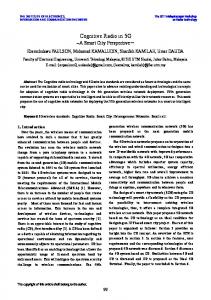
To extend the LTE Application Framework’s eNodeB with support for multiple UEs using OFDMA, there are two main approaches. We first provide an overview of the reference design and then discuss the available options. In this section, we focus on the downlink transmitter. The considerations within apply, with the exception of those concerning the PDCCH, analogously to the uplink receiver. Architectural considerations concerning the uplink receiver are therefore not separately discussed for most of the section. original fpga design Figure 11 depicts a simplified model of the LTE Application Framework eNodeB’s downlink transmitter. Whenever the FPGA starts processing new symbol (i.e., 14 times per millisecond), a Symbol Trigger is issued. The TTI Handling block keeps count of incoming Symbol Triggers and, at every start of a new subframe (i.e., every 14 Symbol Triggers), reads the Dynamic Configuration for the current TTI from the H2T Dynamic Configuration FIFO (refer to Section 3.2.1.1). It then triggers the PDCCH Encoding and PDSCH Encoding blocks by supplying them with the this subframe’s transmission configuration. The PDCCH Encoding block translates the Dynamic Configuration into a DCI message and generates the corresponding IQ samples for the PDCCH. These samples are saved in the Target-Scope (TS) PDCCH Sample FIFO. The PDSCH Encoding block
29
30
system design
Symbol Trigger
Delay Trigger PSS
CRS
UERS Dynamic Configura�on FIFO TTI Handling
IFFT
Baseband IQ data to RF
PDCCH Sample FIFO PDCCH Transmitter
H2T
Payload FIFO
Resource Mapping
TS PDSCH Sample FIFO PDSCH Transmitter TS
H2T
DL TX IQ Processing
Figure 11: FPGA Architecture of the original eNodeB’s downlink transmitter (simplified)
reads payload data from the H2T Payload FIFO and encodes it according to the parameters in the Dynamic Configuration. The generated PDSCH samples are saved in the PDSCH Sample FIFO. A delay of 100 000 clock ticks (520 µs, as the FPGA clocks at a rate of 192 MHz) is applied to the Symbol Trigger before it reaches the DL TX IQ Processing block. This is to ensure that, by the time it is triggered, all PDCCH and PDSCH samples have been generated and are ready in their respective FIFOs. The IQ Processing block is comprised of the PSS, CRS and UERS generation as well as the Resource Mapping block, which assigns all physical channels and signals to their respective REs. It is vital for the operation of resource mapper that all PDCCH and PDSCH samples are available in their respective FIFOs. After resource mapping, the samples are converted to the time-domain by the Inverse Fast Fourier Transform (IFFT) block and passed to the RF blocks for upmixing and transmission. Figure 12 shows a timing diagram of the downlink transmitter’s operation and the interworkings of is modules. In this example, all 100 PRBs are allocated to the served UE. The block sizes in this figure are not to scale. If respecting scale, the Symbol Trigger, which is active for a single clock cycle (i.e., one 192 000 th of a subframe) when issued would not be visible in the figure. It is, however, worth noting that the PDCCH Encoder and the PDSCH Encoder run in parallel and that the execution time of the former is negligible next to that of the latter. option 1: replication of existing logic Considering the architecture of the LTE Application Framework described above, the naïve approach is to extend the FPGA design with more PDCCH and PDSCH Encoding blocks to encode PDCCH and PDSCH samples for multiple UEs. Each encoder needs its own respective sample FIFO in
3.2 extensions to the reference design
start of subframe 0 (PHY)
start of subframe 1 (PHY)
Symbol Trigger PDCCH Encoder
DCI
DCI
PDSCH Encoder
100 PRBs
Delay Trigger
100 PRBs
delay trigger to ensure all PDSCH samples are ready for IQ processing
symbol 11
symbol 10
symbol 9
symbol 8
symbol 7
symbol 6
symbol 5
symbol 4
symbol 3
symbol 2
symbol 1
symbol 0
IQ Processing
start of subframe 0 (air)
Figure 12: Timeline of the original downlink transmitter (not to scale) start of subframe 0 (PHY)
start of subframe 1 (PHY)
Symbol Trigger PDCCH Encoder
DCI 1
PDCCH Encoder
DCI 2
DCI 1 DCI 2
PDCCH Encoder
DCI 3
DCI 3
PDCCH Encoder
DCI 4
DCI 4
PDSCH Encoder
UE 1: 25 PRBs
UE 1: 25 PRBs
PDSCH Encoder
UE 2: 25 PRBs
UE 2: 25 PRBs
PDSCH Encoder
UE 3: 25 PRBs
UE 3: 25 PRBs
PDSCH Encoder
UE 4: 25 PRBs
UE 4: 25 PRBs
Delay Trigger
delay trigger to ensure all PDSCH samples are ready for IQ processing
symbol 11
symbol 10
symbol 9
symbol 8
symbol 7
symbol 6
symbol 5
symbol 4
symbol 3
symbol 2
symbol 1
symbol 0
IQ Processing
start of subframe 0 (air)
Figure 13: Timeline for the replication scenario (not to scale)
which it can place generated samples. The TTI Handling block needs to be expanded to read one Dynamic Configurations for every served UE and supply it to the right PDCCH and PDSCH encoders. Modifications to the resource mapper are necessary for it to keep track of UEs’ resource allocations so that it knows which sample FIFO to read in which PRB. The timing diagram of this approach is depicted in Figure 13. This example uses four PDCCH and PDSCH encoders, respectively, to serve four UEs. The UEs share the available 100 PRBs equally among each other (25 PRBs per UE). While the replication approach is straightforward to implement, duplicating PDCCH and PDSCH encoders takes up additional fabric on the FPGA. In addition to the downlink transmitter, uplink receiver logic (in particular, the PUSCH decoder) needs to be duplicated as well. However, the encoder and decoder blocks are the most complex parts of the FPGA logic and account for the majority of the reference design’s used FPGA slices. It is therefore obvious that this approach scales badly. Experimental builds conducted by National Instruments show that no more than five pairs of PDSCH encoders and PUSCH decoders can fit onto a Kintex-7 FPGA.
31
system design
start of subframe 0 (PHY)
start of subframe 1 (PHY)
Symbol Trigger PDCCH Encoder PDSCH Encoder Delay Trigger
DCI 1
DCI 2
UE 1: 25 PRBs
DCI 3
DCI 4
UE 2: 25 PRBs
DCI 1 UE 3: 25 PRBs
UE 4: 25 PRBs
DCI 2
DCI 3
UE 1: 25 PRBs
DCI 4
UE 2: 25 PRBs
UE 3: 25 PRBs
delay trigger to ensure all PDSCH samples are ready for IQ processing
symbol 11
symbol 10
symbol 9
symbol 8
symbol 7
symbol 6
symbol 5
symbol 4
symbol 3
symbol 2
symbol 1
IQ Processing symbol 0
32
start of subframe 0 (air)
Figure 14: Timeline for the re-use scenario (not to scale)
option 2: re-use of existing logic A more refined approach to share PRBs between multiple UEs is the re-use of existing encoder and decoder logic already present on the FPGA. This approach is based on two observations that can be made from Figures 12 and 13: (i) the execution time of the PDCCH Encoder is negligible compared to that of the PDSCH Encoder and (ii) the PDSCH encoder’s execution time is dependent on the number of allocated PRB. This can be seen by comparing the execution time of the PDSCH encoder in Figure 12 (100 allocated PRBs) with that of the encoders in 13 (25 allocated PRBs). In fact, PDSCH encoder execution time is a function of Transport Block size, which is, in turn, a function of the used MCS and the number of allocated PRBs. The re-use approach exploits these features: After the PDCCH and PDSCH encoders are finished generating one UE’s PDCCH and PDSCH samples, respectively, they are re-run with the next UE’s configuration. This is illustrated in Figure 14, where again four UEs, each with 25 allocated PRBs, are served. As opposed to the duplication example, we only use one instance of the PDCCH encoder and PDSCH encoder, respectively and execute them once for every UE. Like the duplication approach, the re-use approach requires modifications to the TTI Handling and IQ Processing blocks. TTI Handling needs to be adjusted to read several configurations from the Dynamic Configuration FIFO and supply them to the encoders. A mechanism to ensure that the encoders only receive a new configuration when they are ready must be implemented. Depending on the currently processed UE, the PDSCH Encoder needs to place generated samples into one of N FIFOs, with N being the number of supported UEs, so that the resource mapper can know which samples belong to which UE. An equivalent multiplexing mechanism is needed for the PDCCH. In order for the resource mapper to handle multiple UEs, it must keep track of each UE’s PRB allocation in the current subframe so that it knows which UE’s sample FIFO to read in which PRB. Further, a means of supplying multiple traffic-streams to the PDSCH encoders, e.g., multiple separate payload FIFOs, must be implemented.
3.2 extensions to the reference design
Symbol Trigger
Delay Trigger PSS
CRS
Dynamic Configura�on FIFO TTI Handling
PDCCH Sample FIFO Config Dispatcher
H2T
PDCCH Transmitter
Resource Mapping
IFFT
Baseband IQ data to RF
TS
ready
PDSCH Sample FIFOs ready Config Dispatcher ...
[0]
[0] PDSCH Transmitter
...
Payload FIFOs
[7] TS
[7]
DL TX IQ Processing
H2T
Figure 15: FPGA Architecture of our enhanced downlink transmitter (simplified)
As the re-use approach does not duplicate FPGA logic and does not require additional FPGA logic except for additional sample and payload FIFOs, it scales better than the duplication approach. In fact, following this approach, we are able to serve eight UEs with our downlink transmitter. our multi-ue enabled downlink transmitter Our design of the downlink transmitter follows the described re-use approach to enable support for multiple UEs using OFDMA. It provides support for eight UEs. A simplified version of our downlink transmitter’s FPGA architecture is shown in Figure 15. The TTI Handling block is modified to read up to eight Dynamic Configurations from the Dynamic Configuration H2T FIFO. It supplies these configurations immediately, in contiguous clock cycles, to the Config Dispatcher blocks. These new blocks are at the core of our architecture: they buffer incoming configurations and supply them to the following blocks when they are ready. The PDCCH Transmitter is extended by a multiplexer (not shown in the figure) that collects the encoded bits for every scheduled UE and shifts them to their respective CCEs before modulation. The samples generated by the PDCCH Transmitter are therefore already in the right order when they are written to the PDCCH Sample FIFO. We use eight Payload FIFOs to supply the PDSCH Transmitter with each UE’s individual payload bits as well as eight PDSCH Sample TS FIFOs to store each UE’s generated samples. Our enhanced Resource Mapper is supplied with all configurations issued by the TTI Handling block and derives from them which PRB is allocated to which UE. This information is needed for the decision which PUSCH sample FIFO to read when a PUSCH RE is mapped. The reference design’s downlink transmitter supports transmission of UERS on antenna ports seven to fourteen. UERS is a reference sig-
33
34
system design
nal used for beamforming in MIMO setups. As neither the reference design nor our testbed support MIMO, this feature is not needed. To contain the scope of our implementation, we abstain from extending the UERS implementation for multiple users and remove it from our downlink transmitter design. Moreover, the reference design UE supports SRS transmission in uplink. According to 3GPP specifications, the SRS is transmitted over a limited number of TTIs and only when prompted by the eNodeB via higher layer mechanisms. However, the LTE Application Framework does not implement these higher layers and only allows SRS transmission to be turned on or off indefinitely, which leads to collisions when using SRS with multiple UEs. Further, the reference design eNodeB cannot process the received SRS as it lacks the corresponding receiver logic. To contain the scope of this thesis, we refrain from implementing the SRS receiver and a prompting scheme that allows the eNodeB to schedule SRS transmission of multiple UEs. Therefore, we remove the SRS transmitter from our uplink transmitter design. our multi-ue enabled uplink receiver While we are able to successfully implement our downlink receiver using the described architecture and following the re-use approach, the implementation of a multi-UE capable uplink receiver is more challenging and requires a more sophisticated approach. The timing diagram we presented in Figure 14 displays an ideal scenario where the execution time of the PDSCH encoder is quartered along with the the number of allocated PRBs. In practice, this is not the case. The PDSCH encoder (and the PUSCH decoder) is comprised of multiple stages and uses pipelining between them, thus increasing latency to maximize throughput. Our Config Dispatcher block described in Section 3.2.1.2, however, is not optimized to leverage the encoder’s internal pipeline. Instead, it waits until all samples of the currently processed UE are generated before the next configuration is supplied. The pipeline thus runs empty between two configurations. In practice, this means that a considerable part of encoder execution time stems from the initial filling of the pipeline and is therefore constant (i.e., it does not shrink with shrinking transport block sizes). This becomes a problem when serving many UEs: when the combined PDSCH execution time surpasses the duration of one subframe, more configurations arrive at the Config Dispatcher than can be dispatched and eventually, the buffer FIFO overflows, resulting in configurations being dropped. While the execution time of the PDSCH encoder is low enough to support eight UEs, the same cannot be said for the PUSCH decoder. As PUSCH decoder execution time scales with Transport Blokc size and thus with both the number of used RBGs and and the used MCS, we can mitigate this problem by choosing lower MCSs or allocating fewer resources. To give an impression of the severity of the resulting
3.2 extensions to the reference design
Number of UEs
RBGs per UE
(N)
(⌊ 25 N ⌋)
Highest usable MCS
1
25
28
2
12
27
3
8
24
4
6
21
5
5
14
6
4
14
7
3
16
8
3
14
Table 1: Highest usable MCS with in uplink with multiple UEs following the re-use approach
limitations, we show the maximum possible MCS that can be used with any number of UEs N when assigning each UE ⌊ 25 N ⌋ RBGs in Table 1. As can be seen, limitations already apply when scheduling two UEs. With eight UEs, the maximum usable MCS for every UE is MCS 14. This is a severe limitation and would significantly limit the scope and realism of experiments conducted with our testbed. In order to solve this problem, we combine the replication and reuse approaches: we duplicate the PUSCH decoder and re-use both instances. Therefore, each decoder only needs to decode PUSCH transmissions of four UEs. In order to dynamically balance the load between both decoder instances, we implement a scheduler that aims to distribute UEs with high and low transport block sizes evenly among the decoders. Our scheduler uses the following algorithm: 1. Create a list of all UEs and their Transport Block sizes. Treat inactive UEs as having a Transport Block size of zero. 2. Find the UE in the list with the highest Transport Block size. Assign this UE to decoder 0. Remove this UE from the list. 3. Find the UE in the list with the highest Transport Block size. Assign this UE to decoder 1. Remove this UE from the list. 4. Find the UE in the list with the lowest Transport Block size. Assign this UE to decoder 0. Remove this UE from the list. 5. Find the UE in the list with the lowest Transport Block size. Assign this UE to decoder 1. Remove this UE from the list. 6. If the list is empty, terminate. If not, proceed with step 2.
35
36
system design
Our resulting uplink receiver architecture can easily handle eight UEs with all RBGs allocated and MCS 28. We describe our architecture and implementation in more technical detail in Section 4.1.2.2. 3.2.2
Enhanced Cellular Features
Aside from support for multiple users, the LTE Application Framework lacks features, such as transmission of uplink data other than feedback information and dynamic allocation of uplink resources, which we need for our testbed to simulate realistic conditions. uplink data transmission The LTE Application Framework includes an implementation of the PUSCH. However, it is only used to transmit feedback information about the downlink channel. This limitation greatly restricts the scenarios it can be used for. Especially when evaluating the benefits of two UEs communicating via a D2D link versus a cellular link (comprising an uplink to an eNodeB and a downlink from the eNodeB to the destination UE) uplink data transmission is indispensable. We extend the Application Framework’s UE host code to allow for data that arrives at a specified User Datagram Protocol (UDP) port to be transmitted via the PUSCH. Downlink feedback is still transmitted in a feedback header, which is prepended to the payload. The FPGA implementation of the reference design physical layer provides all needed features, such as a PUSCH Payload FIFO which can be used to transmit arbitrary data, and therefore does not need to be changed. We further implement a protocol that allows addressing between UEs. For this means, an addressing header is added in uplink transmissions after the downlink feedback header. We extend the eNodeB host code to process this header and relay received PUSCH data to the destination UE specified in the addressing header. UEs can moreover address a transmission directly to the eNodeB to simulate uplink traffic to the internet. uplink resource allocation In order for UEs to receive PDSCH transmissions and transmit on the PUSCH, information, such as the used PRBs and MCS are required. This information is transmitted via DCI messages on the PDCCH. For the PDSCH, information is, among others, provided via format 1 DCI messages, while SingleInput Single-Output (SISO) uplink resource grants are announced via format 0 DCI messages. The LTE Application Framework, however, only supports DCI type 1 and therefore only downlink resource allocation and MCS control. PRBs and MCS used for PUSCH transmissions have to be manually configured by the user at both the transmitting and the receiving end.
3.2 extensions to the reference design
To allow our testbed to reconfigure uplink transmissions dynamically, we enable the eNodeB to control UEs’ PUSCH transmissions via the PDCCH. To contain the scope of this thesis, we abstain from implementing support for DCI format 0 and instead use type 1 DCI messages with special CCEs offsets. The CCEs used by every UE are tied to that UE’s index. Denoting n as a UE’s index, its downlink DCI message lies in CCEs 4n and 4n + 1. Its uplink DCI message is located in the two following CCEs 4n + 2 and 4n + 3. As the LTE Application Framework uses aggregation level 2, each DCI message occupies two CCEs. extended pdcch The PDCCH implementation in the reference design uses Control Format Indicator (CFI) 1. This means that in every downlink subframe, only the first symbol (minus the REs used for the CRS) is used by the PDCCH. There are 12 subcarriers in a PRB. The CRS uses four REs in the first symbol and our channel bandwidth of 20 MHz corresponds to 100 PRBs. Therefore, there are (12 − 4) ∗ 100 = 800 REs available to the PDCCH. One REG comprises four PDCCH REs and a CCE is made up of nine REGs. The PDCCH in the reference design thus contains ⌊ 800 4·9 ⌋ = 22 CCEs, which can accommodate 11 DCI messages. As discussed under Uplink Resource Allocation, we transmit two DCI message per UE. Since we aim to support eight UEs, we need a PDCCH that is capable of transmitting sixteen DCIs. We therefore extend the PDCCH implementation on the FPGA to use the next higher CFI, namely CFI 2, which means we use the first two symbols for PDCCH. As no other signals occupy REs on the second symbol, our extended PDCCH has 2000 REs or 55 CCEs, respectively, and can thus accommodate a total of 27 DCI messages. This is more than enough to fulfill our goal of supporting eight UEs. 3.2.3
Device-to-Device Links
In addition to the extensions to the cellular links covered so far, our testbed supports direct communication between two UEs via D2D links. Our system supports both inband and outband D2D communications. This section gives an overview of our design changes with regard to the LTE Application Framework to implement inband and outband D2D communications. 3.2.3.1 Inband Device-to-Device Links The 3GPP specifies that, in the case of FDD, uplink frequencies (or, in the case of TDD, uplink subframes) are to be used for D2D communications. To contain the scope of this thesis, our current testbed supports FDD only, with TDD being left for further study. As an uplink transmitter already exists in the reference design’s UE architecture,
37
38
system design
all that is left to be added to the UE design to enable D2D communications is an uplink receiver. For the D2D transmitter, we re-use the existing uplink transmitter logic in the LTE Application Framework. In accordance with the 3GPP specification, we use Time-Division Multiplexing (TDM) for multiplexing uplink and D2D transmissions. We make the following modifications to the TTI Management block of the uplink transmitter to implement TDM: • The Dynamic Configuration format contains an additional MCS and RBG allocation for the D2D link. • The Dynamic Configuration contains a ten-slot array of TX subframe configurations, which specify whether each subframe is to be used for uplink, D2D or no transmission at all (e.g., to listen to an inbound D2D transmission). • Depending on the subframe index, the TTI Handling block outputs either the uplink configuration, the downlink configuration or no valid configuration at all. UEs need to be able to receive D2D transmissions. As the cellularonly UE logic of the reference design only comprises an uplink transmitter and a downlink receiver, an uplink transmitter needs to be integrated manually. This task is not as easy as copying the eNodeB’s uplink receiver logic to the UE’s FPGA, as we need to account for synchronization. System timing and carrier frequencies in LTE are determined by the eNodeB. UEs synchronize themselves with the eNodeB and estimate the Carrier Frequency Offset (CFO) by processing the PSS. A separate synchronization signal, the PSSS is used for D2D communications according to [7]. To contain the scope of this thesis, we do not implement D2D synchronization signals. Instead, we use the eNodeB’s PSS to establish a common timing among the communicating UEs. Figure 16 depicts the FPGA architecture of our D2D-enabled UE. The CFO and timing offset information obtained from processing the PSS in the Synchronization and CFO Estimation block in the downlink receiver chain is shared with the uplink/D2D transmitter and D2D receiver chain. We do not modify the reference design’s uplink transmitter chain with regard to synchronization, which uses timing information to trigger timely PUSCH sample generation. As can be seen, all uplink and D2D transmissions are corrected to reflect the eNodeB’s CFO. We integrate the eNodeB’s uplink receiver logic into the UE’s FPGA design. The eNodeB’s logic, however, does not account for synchronization and CFO compensation as its timing and frequencies reflect the ground truth in a cell and it is the UEs’ responsibility to shape their transmissions accordingly. To adapt the uplink receiver for use in the UE, we prepend a Time Alignment and CFO Compensation block.
3.2 extensions to the reference design
Data from Host
PUSCH Transmitter
CFO Comp.
D2D/Uplink Samples to RF
UL/D2D Transmitter
PDCCH Receiver
Data to Host
PDSCH Receiver
Resource Demapper
Sync. CFO Est. Time Align. CFO Comp.
Downlink Samples from RF
DL Receiver
Data to Host
PUSCH Receiver
Time Align. CFO Comp.
D2D Samples from RF
D2D Receiver Data/Samples Timing Information & CFO DCI
Figure 16: High-level FPGA Architecture of our D2D-enabled UE
This aligns the incoming samples with regard to the downlink timing. As D2D transmissions are, like uplink transmissions, aligned with downlink timing and account for the transmitting UE’s CFO with regard to the eNodeB, we can use the information derived from the PSS to synchronize and CFO-compensate incoming D2D transmissions. 3.2.3.2 Outband Device-to-Device Links We use the 802.11 Application Framework to implement WiFi-based outband D2D links. Like the LTE Application Framework, the 802.11 Application Framework comprises an FPGA part, which implements physical and MAC layer functionality, as well as a host part, which controls the operation of the FPGA, supplies and receives payload data and displays controls and indicators. To simplify the implementation, we do not merge the LTE and 802.11 host or FPGA designs into a single host or FPGA design. Instead, we run the top-level VIs of both Application Frameworks in parallel, each controlling its respective USRP RIO device. We extend the host logic of the 802.11 Application Framework and the LTE Application Framework’s UE to communicate data, such as payload bytes for outband transmission, destination MAC addresses and outband transmission error rates.
39
40
system design
Outband Transmit Queue Outband Control Queue FPGA
Host
Host
FPGA
Outband Feedback Queue 802.11 Application Framework
D2D-enabled LTE UE
Figure 17: Communication between LTE and 802.11 Application Frameworks
Our architecture is shown in Figure 17. We use Queues to communicate between the Top-Level Host VIs as they provide an easy way to exchange data without a common parent VI. As the information whether or not to use the outband link is announced by the eNodeB via LTE (refer to Section 3.2.4), the 802.11 logic is controlled by the LTE UE logic. It uses the Outband Control Queue to control which MAC addresses (source and destination) are to be used for the outband transmission, supplies traffic for the outband link via the Outband Transmit Queue and receives feedback through the Outband Feedback Queue. While the 802.11 Application Framework supports various MCSs and users can manually switch between them at runtime, it does not by default feature AMC. We extend the reference design to add this functionality. As the 802.11 Application Framework does not calculate SINRs, we resort to the Block Error Rate (BLER) as an alternative indicator of channel quality. Our AMC mechanism aims to keep the BLER between one and five percent. 3.2.4
Resource Allocation and Mode Selection
In addition to the physical layer capabilities of our testbed, we design a simple yet effective algorithm for mode selection and resource allocation to perform experimental evaluations with our testbed. We further implement protocols for feedback reporting and signaling to allow the eNodeB to make educated mode selection decisions and communicate them to UEs. feedback reporting and signaling In order to enable our UEs to report channel conditions of the downlink, inband and outband channels to the eNodeB, we extend the reference design’s uplink feedback reporting protocol. By default, the protocol reports the current radio frame number at the UE, downlink subband and wideband SINR measurements and ARQ feedback (ACK/NACK information) on downlink transmissions. Our extended reporting protocol additionally includes subband and wideband SINR measurements for the inband channel, current outband BLERs and the currently used MCS on the outband link as well as downlink, inband and outband throughputs. The latter are only reported to aggregate our simulation
3.2 extensions to the reference design
results at the eNodeB and not used in our mode selection algorithm. In order to allow the eNodeB to control UEs’ use of D2D channels, we introduce a signaling protocol on the downlink channel. This protocol enables the eNodeB to communicate uplink subframe configurations (i.e., which subframes are to be used for uplink and which for inband transmissions) as well as inband transmitter and receiver resource allocations to its UEs. It further allows the eNodeB to tell UEs whether to use the uplink, inband or outband channel for data transmissions (i.e., the current mode selection). We implement both the feedback reporting and signaling protocols via headers that we prepend to downlink and uplink data transmissions. resource allocation As we use windows computers to run the host portion of our testbed, our current host code does not feature real-time capabilities. Because of this, we presently cannot reliably schedule resources on a per-subframe basis. Every time we change resource allocations, the lack of timing guarantees on our host causes an uncontrollable delay of several subframes before the new configuration is communicated to the FPGA. To mitigate this problem, we use a largely static resource allocation that only changes when UEs switch modes. While in cellular mode, we divide all available RBGs in downlink and uplink evenly between users. With eight users, this means that every user gets three downlink and uplink RBGs, respectively. This resource allocation mechanism is similar to the Round Robin scheduler used in LTE as it distributes resources evenly among all users of a system. Instead of time-multiplexing, however, we use frequency-multiplexing. When a UE switches to inband or outband D2D mode, it yields all but one of its downlink RBGs. As the eNodeB transmits signaling information via the downlink channel, it is important that a minimal downlink bandwidth is still ensured to enable reception of, e.g., mode switching commands. While in inband D2D mode, communicating UEs combine their allocated uplink resources to increase the bandwidth of their D2D channel. As we use TDM for duplexing on the inband D2D channel, one UE may transmit in five subframes per frame while the other transmits in four. The tenth subframe is always used for feedback reporting to the eNodeB. In every scheduling interval, we change which UE gets five and which gets four subframes, thus equaling out throughput between the UEs in the long run. In outband D2D mode, each UE keeps its own uplink RBGs and uses all subframes for feedback reporting. In cellular mode, the uplink subframe configuration depends on its communication partner. If a UE communicates directly with the base station, all uplink subframes are used for uplink feedback and data transmission. UEs that communicate with other UEs via cellular relaying use nine subframes per frame for uplink communication and
41
42
system design
one to evaluate the inband D2D channel. In every scheduling interval, we change which UE transmits and which UE receives during the inband subframe. As mentioned above, UEs yield their downlink resources as they switch to D2D mode. In order to make use of freed downlink resources, we distribute them evenly among cellular UEs, i.e., UEs that communicate directly with the base station and simulate downloads from the internet. We assume that they can make the best use of additional downlink resources as their throughput is only limited by their downlink channel. In contrast, a pair of UEs that communicate with each other via the base station is limited in throughput by both UEs’ downlink and uplink channels. As we do not implement dynamic scheduling of uplink resources, we assume that such pairs would profit only marginally from additional downlink resources since their restricted uplink resources would form a performance bottleneck. mode selection Our mode selection algorithm works by estimating the achievable throughput for a pair of communicating UEs on the cellular, inband and outband D2D links, respectively. It selects the mode which is deems to yield the highest throughput or, more precisely, it switches a UE pair’s communication mode if it believes that another link could improve throughput by 10 % or more. Throughputs are estimated for each link based on the currently used MCS and the number of allocated RBGs. We use the tables in Chapter 7.1.7 of [8] to determine the Transport Block Size, i.e., the number of bits transmitted during one TTI, and determine the achievable data rate in bits per second based on the respective subframe configuration that would be used for the link. For cellular relaying, we calculate the expected unidirectional throughput as the minimum of the sender’s achievable uplink throughput and the receiver’s achievable downlink throughput. In order to estimate outband D2D throughput, we use a look-up table with 802.11 throughputs for each MCS under perfect channel conditions (we obtain this data by having two instances of the 802.11 Application Framework communicate over a wire). We multiply the data from this table by one minus the reported outband BLER in order to calculate the outband throughput estimate. Due to the continuous adaptation of each channel’s MCS to the respective channel quality through AMC, our throughput estimates account for the current channel conditions. Our mode selection algorithm is thus ultimately based on each channel’s current quality. 3.3
features and future enhancements
features Our extensions to the LTE Application framework allow our testbed to support eight UEs simultaneously. In cellular mode, UEs can communicate with each other through the eNodeB, which
3.3 features and future enhancements
can relay received uplink data to the desired destination UE. Alternatively, UEs may send data to or receive data directly from the eNodeB to simulate communication with the internet or UEs in other cells. The eNodeB can dynamically assign downlink and uplink resources to UEs and control the used MCSs via DCI messages on the PDCCH. Our downlink feedback protocol enables the eNodeB to send UEs into inband or outband D2D. In these modes, UEs communicate directly with each other without traversing the eNodeB, using inband or outband links. Our inband D2D implementation uses the same frequencies and encodings as the uplink, which is largely compliant with 3GPP specifications. Outband links use 802.11 Application Framework, whose operation is dynamically controlled by the LTE UE. UEs report feedback on the quality and throughput of the downlink channel as well as the inband and outband D2D links, on which scheduling and mode selection decisions can be made. Our testbed enables researchers to evaluate mode selection algorithms for 5G networks in practice. As a proof of concept, we implement a scheduling mechanism that leverages the potentials of inband and outband D2D links to select the link with the highest throughput for every UE pair. We reallocate downlink resources of UEs switching to D2D mode in order to maximize performance and spectral efficiency. potential for enhancements Currently, our testbed supports up to eight UEs. The high execution times of the PUSCH decoder and PDSCH encoder, as addressed in Section 3.2.1.2, make the support of more UEs non-trivial. Furthermore, the USRP RIO platform supports a maximum of 16 T2H and H2T FIFOs combined. Our current implementation uses one payload FIFO per served UE in downlink and the LTE Application Framework uses the other available eight FIFOs, e.g., for visualization of the baseband spectrum on the host. As a possible solution, the U8-typed payload bytes for eight UEs could be multiplexed into a single U64 FIFO. This would require corresponding multiplexing and demultiplexing logic at the host and FPGA. Furthermore, as a regression to the LTE Application Framework, our testbed does not support transmission of SRS in uplink. However, while the LTE Application Framework’s UE supports SRS transmission, the eNodeB cannot process it. We therefore do not consider the lack of support for SRS in our testbed to be a serious regression. We plan to implement the SRS receiver in a future version of the testbed and, at the same time, revise the SRS transmitter to transmit only when requested by the eNodeB and thus enabling it to be used with multiple UEs. This will allow us to obtain channel measurements of the whole uplink channel rather than only the frequencies currently used for the PUSCH.
43
44
system design
We further deviate from the 3GPP specification by using OFDMA instead of SC-FDMA in uplink. Our inband D2D links use PUSCH scrambling, modulation and coding instead of PSSCH. As the difference lies mainly in the values of some parameters, it should be little effort to support a standard-compliant PSSCH in the future. We also plan to implement the PSSS in a future version to enable D2D communications independent of eNodeB coverage. Transmit power control for the uplink and D2D channels is currently not supported by our testbed. We will extend the FPGA implementation to use digital scaling to implement this feature in the future. Using low transmission powers for inband D2D links between close UEs will allow frequencies to be re-used by other UEs for uplink or D2D links, therefore allowing experimentation with underlay D2D systems.
4
I M P L E M E N TAT I O N
In this chapter, we present our implementation of the features described above. We first discuss the work done on FPGA, which mainly concerns the physical layer, in Section 4.1. Higher-layer functionality, such as signaling, feedback reporting, and addressing, is implemented in host code. Section 4.2 covers the respective changes and extensions. 4.1
fpga implementation
In this section, we show how we extend the LTE Application Framework eNodeB’s physical layer design to support multiple UEs and allow direct communication between UEs with inband D2D links. We first discuss limitations of our hardware platform concerning the number of FIFOs and present our way of handling them in Section 4.1.1. This section also gives an overview of the communication FIFOs in our architecture. Our multi-UE extensions to the eNodeB physical layer are covered in Section 4.1.2. Section 4.1.3 presents the changes made to the UE design in order to enable support for D2D links. 4.1.1
FIFO Management
The USRP RIO hardware platform supports a maximum total of 16 T2H and H2T FIFOs. The reference design eNodeB and UE architectures already use twelve and ten FIFOs, respectively. Since our testbed substantially extends the LTE Application Framework regarding both logic and required FIFOs, measures need to be taken to stay within the FIFO limit. As an alternative to FIFOs, terminals can be used for communication of data between the host and FPGA. Unlike FIFOs, their number is not limited by the hardware. Therefore, we replace FIFOs with terminals wherever possible. Further, we use multiplexing to transmit additional data over existing FIFOs. We use multiplexing to make efficient use of those FIFOs we cannot replace with terminals. enodeb design Our multi-UE enabled eNodeB design features the 16 T2H and H2T FIFOs listed in Table 2. As shown in the table, every FIFOs corresponds either to the eNodeB’s downlink transmitter (denoted as DL TX) or uplink receiver (UL RX) with one exception. The reg.host instruction fifo 0 is part of the Register Bus library used by the LTE Application Framework to control the FPGA from the host system. As we do not change the Register Bus logic, we leave this
45
46
implementation
Location
Direction
Reg. Bus
H2T
reg.host instruction fifo 0
H2T
PDSCH Payload 0 .. .
DL TX
FIFO Name
PDSCH Payload 7 T2H
TX Baseband Stream PUSCH Decoded Data 0 PUSCH Decoded Data 1
UL RX
T2H
PUSCH Decoding Status RX Baseband Stream RX Channel Estimates RX Constellation
Table 2: FIFOs in our eNodeB FPGA implementation
FIFO in place. The downlink transmitter comprises eight H2T PDSCH Payload FIFOs, numbered 0 to 7, from which it reads the payload data for each served UE. The TX Baseband Stream FIFO is used to supply selected outbound baseband IQ samples to the host to visualize the spectrum. The uplink receiver uses six T2H FIFOs to communicate received information to the host. To transfer demodulated and decoded PUSCH data to the host, it uses the two PUSCH Decoded Data FIFOs and the PUSCH Decoding Status FIFO. All decoded PUSCH data is written by the two PUSCH decoders to their respective PUSCH Decoded Data FIFO as a stream. The PUSCH Decoding Status FIFO contains meta information that helps the host to dissect these streams into individual transport blocks by different UEs. Like the downlink transmitter, the uplink receiver uses an RX Baseband Stream FIFO to enable spectrum visualization at the host. Moreover, the uplink receiver writes selected PUSCH samples to the RX Constellation FIFO for the host to display a constellation diagram. The RX Channel Estimates FIFO is used to send DMRS-based channel estimates to the host to calculate SINRs. Compared to the reference design, our FPGA architecture adds seven new PDSCH Payload FIFOs to support individual data streams for to up to eight UEs. Furthermore, we add a second Decoded Data FIFO for the additional PUSCH decoder and the RX Channel Estimates FIFO to calculate SINRs for the uplink channel. The SINR is an essential measurement for our eNodeB as it, unlike the reference design eNodeB, supports relaying received uplink data to other UEs. Knowledge of the uplink channel quality is thus crucial for the decision whether to use the cellular or the D2D link for inter-UE communications. Adding these nine new FIFOs to the ten FIFOs in the original design would exceed the 16 FIFO limitation by three. We therefore
4.1 fpga implementation
Location
Direction
Reg. Bus
H2T
FIFO Name reg.host instruction fifo 0 PDCCH Message PDSCH Decoded Data
DL RX
T2H
PDSCH Decoding Status RX Baseband Stream* RX Channel Estimates RX Constellation* D2D RX Channel Estimates PUSCH Decoded Data
D2D RX
T2H
PUSCH Decoding Status RX Baseband Stream* RX Constellation*
H2T UL/D2D TX T2H *
PUSCH Payload 0 PUSCH Payload 1 TX Baseband Stream Timing Indication
Baseband and Constellation FIFOs are used in multiple chains Table 3: FIFOs in our UE FPGA implementation
remove two H2T FIFOs present in the LTE Application Framework eNodeB, namely the DL TX Dynamic Configuration and UL RX Dynamic Configuration FIFOs. Furthermore, we remove the T2H Timing Indication FIFO. As shown in Figure 9, these FIFOs are used in the reference design to signal dynamic configuration information, such as used RBG allocations and MCSs, as well as to indicate the start of a new TTI and the resulting need to supply new configurations. Our implementation supplies uplink and downlink configurations via terminals (cf. Section 4.1.2.1) instead. Similarly, we indicate the start of TTIs via terminals by incrementing a TTI counter. The host periodically checks this counter and, if it has changed since the last read, it concludes that a new TTI has started. ue design Our UE design uses the 14 FIFOs shown in Table 3. Like the eNodeB, it features the reg.host instruction fifo 0 as part of the Register Bus library. The remaining FIFOs are used by the downlink receiver (referred to as DL RX), the D2D receiver (D2D RX) and the uplink/D2D transmitter (UL/D2D TX). The downlink receiver uses the PDCCH Message FIFO to transmit received downlink DCI messages to the host for display and PDCCH BLER calculation. Like the eNodeB’s uplink receiver, the UE’s downlink receiver features
47
48
implementation
PDSCH Decoded Data, PDSCH Decoding Status, RX Baseband Stream, and RX Channel Estimation FIFOs for transmission of received PDSCH payload, display of the baseband spectrum, and downlink SINR calculation. PDCCH samples are written to the RX Constellation FIFO to visualize received control channel constellations on the host. The D2D receiver chain is derived from the uplink receiver chain and thus uses similar FIFOs. It uses the D2D RX Channel Estimates FIFO to implement SINR calculation for the D2D link, the PUSCH Decoded Data and PUSCH Decoding Status FIFOs for received D2D payload and uses the same RX Baseband Stream and RX Constellation FIFOs as the downlink transmitter for spectrum and display at the host. The uplink/D2D transmitter has one payload FIFO for uplink and one for D2D data transmission, the PUSCH Payload FIFO 0 and 1, respectively. For spectrum visualization, baseband IQ samples are written to the TX Baseband Stream FIFO. The Timing Indication FIFO is used to send Timing Indications to the host and thus signal the beginning of a new subframe. Our FIFOs deviate from the LTE Application Framework UE’s FIFOs in a number of ways. Firstly, our introduction of a PUSCH receiver chain adds the respective FIFOs to our UE design. We further add the D2D RX Channel Estimates FIFO to obtain SINR measurements for the D2D channel. As stated above, the downlink and D2D receiver share the RX Baseband Stream and RX Constellation FIFOs. We exploit the design of our user interface, which allows the user to see the spectrum and constellation of either the downlink or the D2D receiver, but not both at the same time. Depending on what perspective the user chooses, either the downlink or the D2D receiver chain writes their samples to the respective FIFOs. We substitute the DL RX, UL RX, and UL TX Dynamic Configuration FIFOs present in the reference design with terminals. This leaves us with 14 T2H or H2T FIFOs in our UE FPGA design, which leaves room to implement further FIFO-based features in the future. It is worth pointing out that the closely related FlexRIO hardware platform, which is used with PCI eXtensions for Instrumentation (PXI) systems and can be programmed and controlled using the same tools as the USRP RIO platform, supports up to 32 T2H and H2T FIFOs. The FPGA code for this testbed can be compiled for FlexRIO with minor modifications to its Register Bus and Radio Frequency (RF) loops. We have successfully verified this with an early prototype version of our code. In the subsequent course of this thesis, however, we only had access to USRP RIO devices, thus requiring us to make efficient use of the 16 available FIFOs as described above.
4.1 fpga implementation
4.1.2
eNodeB FPGA Implementation
The eNodeB FPGA design consists of the following four Clock-Driven Loops: • The Register Bus Loop • The RF Loop • The Downlink Transmitter Loop • The Uplink Receiver Loop The Register Bus Loop is part of the Register Bus library that is used by the Application Framework. In the RF Loop, baseband samples are upconverted to RF and passed to the USRP’s Digital to Analog Conversions (DACs) for transmission. Neither of these loops needs to be modified to implement our testbed. However, changes to both the Downlink Transmitter and Uplink Receiver Loops are necessary to extend the eNodeB reference implementation for our testbed. Although our main modifications are related to multi-UE support, we also enable other features, like an increased number of REs for the PDCCH and DMRS-based uplink channel estimation. We present our modifications to the downlink transmitter and the uplink receiver in Sections 4.1.2.1 and 4.1.2.2, respectively. 4.1.2.1
Downlink Transmitter
In this section, we first give an overview of the downlink transmitter’s high-level operation before presenting each of its components in detail. overview The downlink transmitter performs physical layer tasks for the PDSCH and the PDCCH as well as MAC layer tasks. Its responsibilities include PDCCH and PDSCH encoding and scrambling, resource mapping and OFDM modulation. It also performs header generation for a simple MAC layer which enables frame delimiting. We make the following modifications to the downlink transmitter implementation: • Enabling Multi-UE PDCCH and PDSCH transmission • Increasing the number of DCI messages that can be transmitted via the PDCCH • Enabling uplink DCI transmission via the PDCCH Figure 18 displays the high-level architecture of our downlink transmitter. The control flow begins with the TX Trigger Clock-Driven Logic (CDL), which periodically issues Symbol Triggers, marking the
49
implementation Payload FIFOs
DataPath
[0]
Control Path Trigger Path
...
50
TX Trigger
MAC TX
[7]
PXSCH TX Bit Proc.
Ready Path FIFO References
H2T
DL TX to RF DL TX Configurations
DL TTI Handling
PDSCH TX Config Calc.
DL TX IQ Processing TS TX Baseband Stream
PDCCH Transmitter T2H Timing Indication to Host (via terminal)
Figure 18: High-level architecture of the eNodeB’s downlink transmitter
beginning of a new OFDMA symbol. At a clock rate of 192 MHz, triggers are issued on average every 13 715 cycles (14 symbols per millisecond). The triggers are consumed by the DL TTI Handling CDL, which reads the Dynamic Configurations from the host and outputs a configurations for both the PDCCH Transmitter and PDSCH TX Config Calculation at the start of every subframe. It also informs the host about the beginning of every new TTI by incrementing a subframe counter that is supplied to the host via a terminal on the eNodeB TopLevel FPGA VI. The PDCCH Transmitter receives downlink and uplink DCI messages for the current subframe from the DL TTI Handling CDL and performs PDCCH encoding, modulation and scrambling. Once all UEs are processed, the generated IQ samples are written to the target-scoped PDCCH Sample FIFO. PDSCH generation is handled by the PDSCH TX Config Calculation, MAC TX and PXSCH TX Bit Processing CDLs. PDSCH TX Config Calculation processes downlink DCIs for the current subframe from DL TTI Handling and derives the parameters for the MAC layer and PDSCH encoding. It buffers configurations and supplies them, one at a time, when the following CDLs are ready. Further, it supplies the DL TX IQ Processing CDL with the information which UE uses which RBGs. The MAC TX CDL reads payload bits from the Payload FIFOs, generates a minimal MAC header and supplies the payload bits to the PXSCH TX Bit Processing CDL whenever it is ready. The PXSCH TX Bit Processing CDL performs PDSCH encoding, modulation, and scrambling for. The generated IQ samples are written to one of eight PDSCH Sample FIFOs, depending on the UE for which the PDSCH samples are generated. The DL TX IQ Processing CDL performs resource mapping, thus combining the IQ samples from the PDCCH and PDSCH Sample FIFOs according to the LTE resource grid. It further implements CRS and PSS generation as well as OFDM modulation and Cyclic Prefix (CP) insertion. The generated baseband IQ samples are written to the DL TX to RF and TX Baseband Stream FIFOs for transmission and spectrum visualization, respectively.
4.1 fpga implementation
The following paragraphs describe the above mentioned six CDLs and their modifications in detail. dl tti handling This CDL reads Dynamic Configurations from the host and supplies them, at the start of every subframe, to the PDCCH and PDSCH transmitter chains. The reference design uses a FIFO to read configurations from the host. Due to the reasons given in Section 4.1.1, we replace this FIFO by a terminal. We further modify this CDL to handle the Dynamic Configurations of up to eight UE. This CDL as the following inputs: • A Symbol Trigger, issued by the TX Trigger CDL • An eight-slot DL TX Configs array and the Static Downlink Configuration, both provided by the host via terminals on the TopLevel eNodeB FPGA VI The elements of the DL TX Config array contain both a Downlink TTI Configuration and an uplink DCI. Downlink TTI Configuration clusters are comprised of a downlink DCI and a Dynamic Configuration, which in turn contains UE-specific configuration data such as the RNTI and CCE offset. The Static Downlink Configuration holds non-dynamic parameters for the downlink transmitter, such as the cell ID and the frame structure. This CDL processes incoming Symbol Triggers and produces a Timing Cluster, which holds information about the current timing (e.g., subframe index, symbol index, start of symbol and start of subframe flags, etc.). The generated Timing Cluster is output to the PDCCH and PDSCH transmitter chains. At every start of a subframe, the current DL TX Configs array supplied by the host is saved in a feedback node. We do this to ensure that the array does not change during this TTI. In the following cycles, we iterate over the array and output one UE’s downlink TTI configuration and uplink DCI per clock cycle for eight contiguous cycles, i.e., UE 0’s configuration in the first cycle, UE 1’s configuration in the second cycle, etc. Feedback nodes delay the generated timing clusters so that the first UE’s configuration is time-aligned with the start of subframe Timing Cluster at the output of this CDL. As the host may mark supplied DL TX Configs as invalid, there can be TTIs in which no transmissions are scheduled. In these cases, this CDL outputs an Empty PDCCH Trigger to the PDCCH Transmitter. Also, at the start of every TTI, this CDL increments a subframe counter and outputs it as a terminal to the host in order to poll it for a new configuration array. pdcch transmitter The PDCCH Transmitter is responsible for the generation of PDCCH baseband IQ samples. We extend the reference implementation to support DCI encoding for multiple UEs
51
52
implementation
Data Path Control Path Trigger Path
Empty PDCCH Trigger Downlink Configuration Uplink DCI Message
PDCCH Config Dispatcher
delay
∨
DCI Dispatcher
DCI Encoder
Ready Path
PDCCH MUX
PDCCH Scramb. Interl. Mod.
PDCCH Samples
Static Configuration Timing Cluster
Figure 19: Architecture of the PDCCH Transmitter DCI #1 Offset: 0 DCI #2 Offset: 12 DCI #3 Offset: 10 DCI #4 Offset: 4
PDCCH MUX
DCI #1 0 2 CCE Index
DCI #4 4
DCI #3 6
8
10
DCI #2 12
14 …
Figure 20: Operation of the PDCCH MUX
and transmission of uplink DCI messages. The architecture of our enhanced PDCCH Transmitter is depicted in Figure 19. Its inputs are the following: • The Empty PDCCH Trigger, the Downlink Configuration, the Uplink DCI Message, and a Timing Cluster, all provided by the DL TTI Handling CDL • The Static Downlink Configuration, provided by the host As mentioned above, Downlink Configurations and DCI Messages for each UE are output by the TTI Handling CDL in contiguous clock cycles. The DCI Encoder, however, has an execution time of several hundred clock cycles and cannot handle multiple configurations at once. We thus extend the reference design PDCCH Transmitter by the PDCCH Config Dispatcher and DCI Dispatcher blocks shown in Figure 19. The PDCCH Config Dispatcher consumes incoming Downlink Configurations and Uplink DCI Messages and buffers them. It combines the downlink and uplink DCI messages into a cluster and stores it in an internal FIFO. When the following CDL signals that it is ready, an element from the FIFO is read and output. When the last element is read from the FIFO, it outputs a last element out trigger (orange arrow). The DCI Dispatcher works similarly: it consumes incoming DCI clusters and stores the downlink and uplink DCIs as well as their respective CCE Offsets in an internal FIFO buffer. The CCE Offset of the downlink DCI is contained in the incoming cluster and the respective uplink CCE Offset can be derived by adding two to the downlink offset. When the DCI Encoder CDL signals readiness, the DCI Dispatcher supplies it with a DCI message from the FIFO and additionally outputs the corresponding CCE Offset for the PDCCH
4.1 fpga implementation
MUX. We do not change the DCI Encoder itself. It encodes an input DCI message into bits, which are supplied at its output in pairs (i.e., arrays) of two to facilitate later QPSK modulation. The PDCCH MUX stores incoming bits and arranges them according to their CCE Offset. When a readout trigger (orange arrow) is supplied, it outputs the stored PDCCH bits. In the reference design, this CDL would simply delay bits to shift them to their respective CCE. To support multiple UEs, the PDCCH MUX is completely re-written to work on an internal block of memory, in which each element represents a PDCCH RE. The address (i.e., the REs) to which incoming bits are written is calculated from their CCE Offset. When a readout trigger is supplied, the contents of the memory are output. The number of PDCCH REGs is read from the Static Configuration. The PDCCH Scrambler Interleaver Modulator CDL performs the tasks suggested by its name. It consumes a Static Configuration to read the number of REGs in the system. We modify this CDL to increase the memory area on which the interleaver works. This is necessary because our testbed uses CFI 2 and therefore 2000 instead of 800 PDCCH REs. At the beginning of a TTI, the DL TTI Handling CDL supplies the PDCCH Transmitter with downlink and uplink configurations for up to 8 UEs. Each UE’s configuration is buffered by the PDCCH Config Dispatcher. The first UE’s configuration is passed to the DCI dispatcher, which supplies first the downlink and then the uplink DCI to the DCI Encoder. All encoded samples are stored by the PDCCH MUX. Once the PDCCH Config Dispatcher outputs the last UE’s configuration, a readout trigger is issued to the PDCCH MUX. This trigger is delayed to allow the DCI Dispatcher and Encoder to finish processing the last UE’s DCI messages. Upon trigger reception, the PDCCH MUX outputs all PDCCH bits for this TTI to the PDCCH Scrambler Interleaver Modulator, which produces this TTI’s PDCCH baseband IQ samples. If no UE is active in a TTI, the DCI Encoder is not executed and the PDCCH MUX is triggered directly via the Empty PDCCH Trigger. pdsch config calculation The PDSCH Config Calculation CDL controls the PDSCH Transmitter components of the downlink transmitter. We modify its logic to manage PDSCH configurations of multiple UEs. Changes are further necessary to the encoder parameter calculation to support the extended PDCCH, which uses CFI 2. Our PDSCH TX Config Calculation architecture as well as its interworkings with the other PDSCH Transmitter CDLs are depicted in Figure 21. This CDL’s inputs are: • The Downlink Configuration and the Timing Cluster, both provided by DL TTI Handling • The Static Downlink Configuration, provided by the host
53
implementation
Payload FIFOs
DataPath
[0]
Control Path Trigger Path
...
54
Ready Path
[7]
FIFO References
H2T
Downlink Configuration Static Configuration
PDSCH Config Dispatcher
DCI To Enc Params
Timing Cluster PDSCH TX Config Calculation
MAC TX
PXSCH TX Bit Proc.
PDSCH Samples Symbol Trigger
RB Allocation
Figure 21: Interworkings of the PDSCH Transmitter CDLs
• A Next Config Trigger, issued by PXSCH TX Bit Processing As opposed to the architecture shown in Figure 21, not all outputs of this CDL are produced by the DCI To Encoder Parameters subCDL. Instead, the output clusters are assembled via complex wiring from components of the sub-CDL and input clusters. For the sake of simplicity, however, we assume for this explanation that the assembly of all outputs occurs in DCI To Encoder Parameters. Our extended PDSCH TX Config Calculation serves two purposes, as reflected by its two components shown in Figure 21: buffering of Downlink Configurations and calculation of the MAC and PDSCH parameters. The first task is performed by its PDSCH Config Dispatcher CDL, which operates identically to the Config Dispatcher in the PDCCH Transmitter except that it manages Downlink Configurations only. The DCI To Encoder Parameters CDL processes Downlink Configurations output from the Config Dispatcher and derives the configuration of the PDSCH encoder. This includes, e.g., the number of allocated REs, the transport block size and the redundancy version index. It also issues a PDSCH Transmitter Trigger that is passed to MAC TX and PXSCH Bit Processing and, when the input Timing Cluster indicates the start of an OFDM symbol, an OFDM Symbol Trigger. We modify this CDL to: • Consider the additional REs used by the extended PDCCH when calculating the PDSCH REs • Append a UE index field to the PDSCH transmitter trigger. The UE index is calculated as CCE Offset 4 • Output the Resource Block Allocation as well as the corresponding UE index for each processed downlink configuration. This is used as an input at the PDSCH IQ Processing CDL mac tx The MAC TX CDL reads payload bits, which are supplied by the host via T2H FIFOs. It further adds a simple MAC header and is rate-controlled by the PXSCH Bit Processing CDL. We extend
4.1 fpga implementation
this CDL to support multiple UEs and thus payload FIFOs. It has the following inputs: • The Payload FIFO cluster, holding references to the eight Payload FIFOs • A PDSCH Transmitter Trigger and the transport block size, both of which are provided by PDSCH Config Calculation • A ready for output flag that indicates whether the PXSCH Bit Processing CDL is ready to process new payload bits The purpose of this CDL is to supply a Transport Block of payload bits to the PDSCH Encoder. In TTIs where the Transport Block size exceeds the amount of data in the respective Payload FIFO, padding is used to fill the remaining bits of the Transport Block. In order for the receiver to be able to separate payload and padding, a header called the MAC header is generated. This header consists of a 32-bit unsigned integer value which represents the number of payload bits in this Transport Block. While we do not change the header generation logic, we extend the MAC TX CDL to manage multiple Payload FIFOs. We use the UE index in the PDSCH Transmitter Trigger (cf. PDSCH Config Calculation) to select the respective UE’s Payload FIFO from the Payload FIFO cluster. The index is saved in a feedback node, which is activated by the PDSCH Transmitter Trigger, thus memorizing the currently selected Payload FIFO until the next trigger arrives. pxsch tx bit processing This CDL performs encoding, deserializing, scrambling and modulation of the PDSCH payload. The name PXSCH TX Bit Processing refers to the fact that it can be used both for PDSCH and PUSCH generation. As the used channel encoder has a considerable latency, this CDL delays the OFDM Symbol Trigger to ensure that all PDSCH samples are generated before the trigger reaches the DL TX IQ Processing CDL. We extend the PXSCH TX Bit Processing to allow it to be executed multiple times within a TTI, following the Re-Use Approach presented in Section 3.2.1.2. Its inputs are: • One bit of MAC data from the MAC TX CDL • The PDSCH Transmitter Configuration, the PDSCH Transmitter Trigger, and the OFDM Symbol Trigger, all provided by PDSCH Config Calculation The PXSCH TX Bit Processing CDL consists of three main subCDLs: the PXSCH Channel Encoder and the PXSCH Deserializer Scrambler Modulator, each performing the tasks implied by their name, and the Trigger Delay CDL. This latter CDL delays up to ten trigger signals
55
implementation Static Configuration Symbol Trigger
Resource Mapper
RB Allocation
IQ Sample Path
IFFT Start Pulse Channel Cluster Timing Indices
Control Path Trigger Path FIFO Reference(s) PSS
PDSCH Sample FIFOs CRS
[0] ...
56
[7] PDSCH Samples
TS Write FIFO*
Read FIFO*
∨
IFFT
CP insertion
Baseband IQ Sample Out
PDCCH Sample FIFO
PDCCH Samples
TS Write FIFO
Read FIFO
Figure 22: Architecture of the DL TX IQ Processing CDL
in parallel by 100 000 cycles. This is the time needed by the PXSCH Channel Encoder to process payload bits in the worst case scenario (i.e., when using the maximum Transport Block size). In the reference design, the PXSCH TX Bit Processing CDL does not have a Ready for Configuration output, which could be used for rate control. We thus extend TX Bit Processing to report when it is ready to process a new configuration. At every incoming PDSCH Transmitter Trigger, we save the current PDSCH Transmitter Configuration’s Number of REs attribute in a Feedback Node. We then count symbols output by the PXSCH Deserialized Scrambler Modulator. When this count is equal to the number of REs from the configuration, we know that all symbols for this configurations are generated. In this case, we output a Ready for Configuration trigger and reset the symbol counter for the next configuration. Due to the reasons discussed in Section 3.2.1.2, treating the PDSCH Encoder as a black box and not exploiting its internal pipeline leads to higher encoder execution times. To account for this, we delay the Symbol Trigger by 190 000 instead of 100 000. The Trigger Delay CDL can only delay ten triggers simultaneously, but up to 14 triggers are expected to arrive during 190 000 clock cycles. We therefore extend the Trigger Delay CDL to support simultaneous delay of up to 20 trigger signals. Furthermore, we modify the output format of the PXSCH TX Bit Processing CDL by tagging each generated PDSCH symbol with the Downlink Configuration’s UE index to ensure that it lands in the right sample FIFO. dl tx iq processing The DL TX IQ Processing CDL performs IQ sample buffering, resource mapping, generation of the PSS and CRS as well as OFDM modulation. Aside from these main tasks, it serves minor secondary functions, such as power measurement. Here, we focus on the main functionality and, in particular, on the parts modified to enable handling multiple UEs. Figure 22 shows the architecture of the DL TX IQ Processing CDL, focussing on its main tasks. It has the following inputs:
4.1 fpga implementation
• The Static Configuration, which is supplied by the host • The Resource Block Allocation from PDSCH Config Calculation • The Symbol Trigger and a PDSCH Samples cluster, comprised of an IQ sample and its respective UE index, both provided by PXSCH TX Bit Processing • A PDCCH Sample, generated by the PDCCH Transmitter This CDL collects incoming PDSCH and PDCCH samples in its internal buffer FIFOs, the PDCCH and PDSCH Sample FIFOs. To separate PDSCH samples of multiple UEs, we replace the reference design’s PDSCH Sample FIFO with a cluster of eight FIFOs, one per UE. We implement CDLs that enable us to write and read the cluster like a regular FIFO. These CDLs are denoted as Write FIFO* and Read FIFO* in Figure 22. One of their inputs is the index of the FIFO, which is to be written or read, respectively. In case of Write FIFO*, this index is provided as part of the input cluster. Read FIFO* requires the index to be passed as a separate terminal. We extend the Resource Mapper to process Resource Block Allocations. These consist of a resource block allocation bitmap and a UE index. The Resource Mapper internally builds a table which Resource Block is allocated to which UE. It keeps track of system timing by processing incoming Symbol Triggers and generates Timing Indices clusters. If the start of a new subframe is detected, the internal resource allocation table is reset. For every received symbol trigger, an IFFT Start Pulse is issued to trigger modulation of an OFDM symbol. In the 2048 cycles following a Symbol Trigger, a Channel Cluster and a Timing Indices cluster are output in every cycle. This cluster indicates which channel or signal (i.e., PDSCH, PDCCH, PSS, CRS or none) is mapped to the subcarrier currently indicated by the Timing Cluster. Only one channel or signal may be assigned to each RE. As an extension to the reference design, our implementation of the Channel Cluster additionally specifies the UE index for PDSCH subcarriers. We further modify the Resource Mapper’s Channel Cluster generation sub-CDL to reflect that we use CFI 2 for the PDCCH. Our implementation maps the first two symbols instead of just the first symbol of every subframe to PDCCH. Depending on the channel or signal indicated by the Channel Cluster, either a PSS or CRS symbol is generated by triggering the PSS or CRS CDL, respectively, or pre-generated PDSCH or PDCCH sample is read from one of the Sample FIFOs. For PDSCH subcarriers, the FIFO to read is determined by the UE index in the Channel Cluster. The generated samples are subsequently ORed. As PSS, CRS and Read FIFO output zero when not triggered, this is a resource-efficient way of merging the data flow and selecting the one sample that is not zero. The resulting samples are subsequently OFDM-modulated
57
58
implementation
DataPath PUSCH Decoded Data
Control Path RX Channel Estimates
Trigger Path Ready Path
T2H
FIFO Reference
T2H
UL RX from RF UL RX Input FIFO Read
PUSCH RX Sample Select
UL RX IQ Processing
TS UL RX Configurations
Calculate PUSCH Config
RX Baseband Stream
T2H
Constellation Symbol Number Constellation UE Index
PXSCH RX Bit Processing
UL RX Constell. FIFO Write
PUSCH Decoder Status
T2H
RX Constellation
T2H
Figure 23: High-level architecture of the eNodeB’s uplink receiver
by the IFFT and CP Insertion CDLs. After modulation, the baseband IQ samples are output to be passed to the RF Loop and the host. 4.1.2.2
Uplink Receiver
In this section, we present our eNodeB’s uplink receiver and highlight our modifications. We first give an overview of the CDLs that comprise the uplink receiver before discussing each one in detail. overview The uplink receiver performs physical layer tasks for PUSCH reception. Its responsibilities include OFDM demodulation, resource demapping, channel estimation and correction as well as PUSCH decoding. The processing of received MAC headers does not occur on the FPGA and is implemented in host logic. We make the following modifications to the uplink receiver: • Enabling simultaneous reception of multiple PUSCH transmissions • Enabling channel estimation for uplink SINR calculation Figure 23 displays our extended uplink receiver architecture. The UL RX Input FIFO Read CDL reads received baseband samples from the UL RX from RF FIFO, which is filled by the RF Loop, and passes the samples on to the following CDL as well as the RX Baseband Stream FIFO. It further counts samples to derive Start of Symbol Triggers, which are issued towards the Calculate PUSCH Config and UL RX IQ Processing CDLs. Since we do not modify this CDL, we do not discuss it in detail below. Like in the downlink transmitter, we receive the UL RX Configurations from the host via a terminal. The Calculate PUSCH Config CDL consumes the UL RX Configuration and derives the corresponding PUSCH Receiver Configuration. It counts Symbol Triggers and, at every start of a subframe (i.e., every 14 triggers) outputs the saved configurations to the PUSCH RX Sample Select CDL.
4.1 fpga implementation
It also supplies the UL RX IQ Processing CDL with every active UE’s Resource Block Allocation at the start of every subframe. The UL RX IQ Processing CDL performs OFDM demodulation and channel equalization. It assigns each incoming sample to its corresponding signal or channel and tags PDCCH samples with the respective UE index. The equalized samples are passed, along with their meta-information, to the following CDLs. UL RX Constellation FIFO Write writes the equalized samples for a selected UE to the RX Constellation FIFO. The information which UE to select is received from the host via the Constellation UE Index terminals. PUSCH RX Sample Select sorts received PUSCH samples into separate FIFOs, depending on their respective UE. It buffers these samples and their corresponding PUSCH Receiver Configurations until a TTI is complete and derives a scheduling for dispatching configurations onto decoders. It then supplies the two PXSCH RX Bit Processing CDLs with the configurations and samples, one UE per decoder at a time. The PXSCH RX Bit Processing CDLs performs soft-bit demapping, descrambling and decoding of the PUSCH payload. Decoded data is written as a stream into the respective PUSCH Decoded Data FIFO. Both instances write meta-information about the demodulated data, such as Transport Block size, subframe number, UE index, and decoder index, to the PUSCH Decoder Status FIFO. In the following, we describe our modifications to each CDL in detail. As we do not alter the inner workings PXSCH RX Bit Processing CDL and merely surround it with our multiplexing logic, we do not discuss it in an own paragraph. calculate pusch configuration This CDL receives Uplink Receiver Configurations from the host and derives the PUSCH Configuration. It is therefore similar to the DL TTI Handling and PDSCH Config Calculation in the downlink transmitter. However, its logic is simpler due to the absence of control channel support in the uplink. The inputs of this CDL are the following: • A Symbol Trigger issued by the UL RX Input FIFO Read CDL • An eight-slot Array of Uplink RX Configurations, which contains, e.g., the RNTIs, Resource Block Allocations, MCSs, and uplink subframe configuration for the served UEs, and is provided by the host via a terminal Like the DL TTI Handling, this CDL generates a Timing Cluster from the received Symbol Triggers and saves the currently supplied Uplink RX Configurations in a feedback node at the start of a new subframe. When a subframe starts, it generates PUSCH Receiver Configurations including, e.g., the number of REs, Transport Block size and modulation, for each element and outputs them in contiguous cycles. We extend the PUSCH Receiver Configuration format to also hold a UE index, which we derive from the configuration’s position in
59
60
implementation
Data Path Control Path Trigger Path Baseband Sample Symbol Start RB Allocation Frame Structure
CP Removal
FFT
UL Resource Demapper
Channel Estimation DMRS
Channel Equalizer
Equalized Sample Channel Estimate Resource Map and Timing
Figure 24: Architecture of the UL RX IQ Processing CDL
the array supplied by the host. Depending on a UE’s uplink subframe configuration and the number of the current subframe, we mark its configuration as invalid before outputting it in subframes in which the respective UE does not transmit an uplink signal. We further modify this CDL to output a second cluster, which contains the Resource Block Allocation tagged with the respective UE index, in parallel to the PUSCH Receiver Configuration. This cluster is consumed by the UL RX IQ Processing CDL. ul rx iq processing This block performs OFDM demodulation and equalization of the received baseband signal as well as resource mapping. We extend its Resource Mapper and Channel Estimation logic to support multiple UEs. Our extended architecture is displayed in Figure 24. Its inputs are: • A received baseband IQ sample from the UL RX Input FIFO Read CDL • A UE’s Resource Block allocation from the Calculate PUSCH Configuration CDL • The Frame Structure, which is provided by the host as a part of the Static Configuration • A Symbol Start trigger issued by the UL RX Input FIFO Read CDL We remove the Cyclic Prefix in the CP Removal CDL and convert the baseband samples into the frequency domain with the FFT CDL. The Resource Mapper collects UEs’ Resource Block Allocations supplied by the PUSCH Configuration CDL at the start of every subframe and derives a table, which Resource Block is allocated to which UE. Since the FFT has a latency of 5285 cycles, the Resource Mapper has knowledge of all Resource Block Allocations when the first samples arrive from the FFT. As the FFT outputs all samples in contiguous clock cycles without gaps, the start of a new symbol can be derived from a valid sample arriving after an invalid sample. At the start of every symbol, the Resource Mapper generates Timing Clusters and Channel Clusters for every subcarrier and outputs them synchronously with the corresponding samples, thus mapping the samples to the channels
4.1 fpga implementation
and signals indicated in their Channel Cluster. The Channel Estimation DMRS CDL uses this information to isolate the DMRS samples and estimates the channel by comparing the received DMRS with the expected sequence. We extend this CDL to handle multiple UEs, each transmitting their DMRS, by replicating the internal DMRS sequence generation CDL eight times. The Channel Equalizer uses the generated estimates to equalize the baseband samples. To perform uplink channel estimation in order to enable SINR calculation at the host, we wire the Channel Estimates produced by the Channel Estimation CDL to a terminal so that they can be passed to the host via the RX Channel Estimates FIFO. ul rx constellation write To enable constellation display at the host for each UE, we extend the UL RX Constellation Write CDL to distinguish between UEs. It has three inputs: • An Equalized Sample and its respective Resource Map and Timing from the UL RX IQ Processing CDL • The Constellation Symbol Number and the Constellation UE Index, both provided by the host via terminals and specifying which samples should be written The implementation of this CDL is straightforward: It marks only samples as valid which correspond to the UE and Symbol Number specified by the host. Only valid samples are written to the RX Constellation FIFO. pusch rx sample select In the reference design, the PUSCH RX Sample Select CDL is used to forward only those samples to Bit Processing which correspond to the PUSCH and to assemble the configuration for the Bit Processing. We completely re-write and greatly extend the logic of this CDL to dispatch both configurations and PUSCH samples to two instances of PXSCH RX Bit Processing. We further implement a mechanism to schedule UEs onto the two decoder instances in order to distribute the load. The architecture of our revised PUSCH RX Sample Select is depicted in Figure 25. It has the following inputs: • The Static Uplink Configuration, which is supplied by the host via a terminal • The PUSCH Configuration provided by the PUSCH Configuration Calculation • The Resource Map and Timing and an Equalized Sample, both produced by the UL RX IQ Processing • A Ready for Configuration trigger issued by the PXSCH RX Bit Processing CDL
61
implementation
Static Configuration Delay PUSCH Config
PUSCH Configuration
Build Receiver Config
UL Config Dispatcher
Ready for Config 0 Resource Map and Timing
PUSCH Receiver Configuration 0 PUSCH Receiver Configuration 1
Data Path
Ready for Config 1
Control Path Trigger Path PUSCH Sample FIFOs
Ready Path FIFO References
[0] ...
62
Read Out FIFO
PUSCH Sample 0
Read Out FIFO
PUSCH Sample 1
[7] Equalized Sample
TS
Write FIFO*
Figure 25: Architecture of the PUSCH RX Sample Select CDL
Our implementation of PUSCH RX Sample Select uses eight FIFOs to buffer equalized PUSCH samples, similar to the buffer FIFOs used in the downlink transmitter. The Write FIFO* CDL processes incoming samples and their corresponding Resource Map and Timing clusters and, if the sample is a PUSCH sample, writes it to the FIFO corresponding to its UE index. It counts how many samples were written to each FIFO in the current TTI and supplies this number to the Read Out FIFO CDL (yellow arrow). At the start of every subframe, the counters are reset. Delay PUSCH Config consumes incoming PUSCH Configurations and delays them until valid Timing Clusters arrive. As mentioned before, the FFT in the UL RX IQ Processing CDL has a latency of 5285 cycles. This means that the PUSCH Configurations, which are supplied from the PUSCH Configuration Calculation and do not traverse UL RX IQ Processing, arrive more than 5000 cycles earlier than the first valid Timing Cluster. Since the correct operation of Build Receiver Config relies on both valid Timing Clusters and PUSCH Configurations, we introduce this delay to synchronize them. Furthermore, while waiting for the first valid Timing Cluster, this CDL derives the scheduling of UEs onto our two decoder instances using the algorithm described in Section 3.2.1.2. It tags output configurations with the index of the respective decoder. The task of Build Receiver Config is to assemble the configuration for the PXSCH RX Bit Processing CDL. This task consists of building a cluster with values from other clusters and reflects the behavior of the original PUSCH RX Sample Select CDL. One field of the configuration is the U32 user data field. The Bit Processing CDLs pass simply pass this value through and report it as-is in their Decoder Status output. While the reference design only populates user data with the subframe index, our implementation writes the subframe, the UE index and the decoder index, all as U8s, to this field. This enables the host to determine which UE is associated with which Transport Block and in which Decoded Data FIFO to find the respective Transport Block. The UL Config Dispatcher
4.1 fpga implementation
buffers generated PUSCH Receiver Configurations and issues them one, one configuration per decoder at time, when a PXSCH Bit Processing CDL signals readiness. It counts the number of configurations received in a subframe (hence the need for its Timing Cluster input). Even if Bit Processing is ready, it does not dispatch configurations until it has received all configurations of the next subframe. This ensures that all samples for the to-be-dispatched subframe are buffered in the PUSCH Sample FIFOs. When the UL Config Dispatcher dispatches a configuration, it triggers the respective decoder’s Read Out FIFO CDL. This trigger includes the UE index of the dispatched configuration. Read Out FIFO reads and outputs all samples that have been written to one of the Sample FIFOs in the last subframe. The number of written samples for the last subframe to each FIFO is supplied to it by the Write FIFO* CDL. We have two instances of this CDL to serve the two PXSCH Bit Processing CDL on the Top-Level FPGA VI. Figure 26 illustrates the operation of PUSCH RX Sample Select and how it controls the execution of the PXSCH RX Bit Processing CDL. This example is simplified as it abstracts parts of this CDL’s internal logic and only considers one decoder. In step one, it buffers incoming PUSCH samples as well as configurations. Once a TTI (i.e., a subframe) is complete and all configurations and PUSCH samples are buffered, the Config Dispatcher begins outputting configurations. Along with each issued configuration, the Read Out FIFO CDL outputs the corresponding PUSCH samples for the PXSCH RX Bit Processing to demodulate and decode. Once Bit Processing is done with a configuration, it issues a Ready for Configuration trigger and PUSCH RX Sample Select dispatches the next configuration and batch of samples. 4.1.3
UE FPGA Implementation
The FPGA architecture of our D2D-enabled UE contains the following five Clock-Driven Loops: • The Register Bus Loop • The RF Loop • The Downlink Receiver Loop • The D2D Receiver Loop • The Uplink/D2D Transmitter Loop Like in the eNodeB design, we do not modify the Register Bus Loop. Therefore, it is not discussed in this section. We modify the Downlink Transmitter Loop to handle the PDCCH, which now uses
63
64
implementation
1
Decoder status Conf Conf Conf
T2H PXSCH RX Bit Processing
Config Dispatcher samples in
PUSCH Sample FIFOs
Payload data
T2H
Read Out FIFO
TS
PUSCH RX Sample Select
2
Decoder status
T2H Conf Conf Conf
PXSCH RX Bit Processing
Config Dispatcher
PUSCH Sample FIFOs
Payload data
T2H
Read Out FIFO
TS UE1 samples UE2 samples UE3 samples
PUSCH RX Sample Select
3
Decoder status
T2H
Conf Conf
Config Dispatcher
PUSCH Sample FIFOs
PXSCH RX Bit Processing
Conf Read Out FIFO
TS
Conf
Payload data
T2H
UE1 samples
UE2 samples UE3 samples PUSCH RX Sample Select
4
Decoder status
T2H
Conf Conf
Config Dispatcher
PUSCH Sample FIFOs
TS
ready
PXSCH RX Bit Processing
Payload data
T2H
Read Out FIFO
UE2 samples UE3 samples PUSCH RX Sample Select
Figure 26: Interoperation of PUSCH RX Sample Select and Bit Processing (simplified)
4.1 fpga implementation
RX Baseband Stream BB stream enable DL TX
Write Baseband Stream
T2H
PDSCH Decoded Data RX Channel Estimates
Time & Freq. Offset T2H T2H DL RX from RF DL RX Sync Top TS
DL IQ Sample Buffer
DL RX IQ Processing
PDSCH RX Sample Select
PXSCH RX Bit Processing UL DCI
UL RX Configurations
Get PDSCH Dyn.Config
PDCCH RX Top
PDSCH Decoder Status
T2H PDCCH Message
T2H
IQ Sample Path Control Path Trigger Path FIFO Reference
Constellation Symbol Number Constellation enable DL RX
DL RX Constell. FIFO Write
RX Constellation
T2H
Figure 27: High-level architecture of the UE’s downlink receiver
CFI 2, extend the reference design’s Uplink Transmitter to an Uplink/D2D Transmitter and add the D2D Receiver. Since our new design uses three radio interfaces, we also need to modify the RF Loop to enable sample reception for the D2D Receiver. We discuss our extensions to the downlink receiver in Section 4.1.3.1. The integration of the D2D Receiver, including the necessary modifications of the RF Loop, are described in Section 4.1.3.2. Section 4.1.3.3 covers the extension of the Uplink Transmitter into an Uplink/D2D Transmitter. 4.1.3.1
Downlink Receiver
As in the previous section, we first give an overview of the downlink receiver’s general architecture and then discuss our modifications in detail. overview The downlink receiver performs PDCCH and PDSCH physical layer operations, such as synchronization, CFO compensation, OFDM demodulation, resource demapping descrambling and decoding. MAC header processing is performed at the host. We make the following changes to the downlink receiver reference design: • Adapting the PDCCH reception to support CFI 2 • Enabling reception of the uplink DCI message • Enabling FIFO multiplexing for the Baseband Stream and Constellation FIFOs The architecture of the downlink receiver is shown in Figure 27. It is similar to that of the uplink receiver, but it features additional synchronization logic and a PDCCH receiver. Synchronization and CFO correction are achieved by the DL RX Sync Top CDL. The measured
65
66
implementation
time and frequency offset are stored in a register so that the D2D receiver and Uplink/D2D Transmitter Loop can read it. Received samples are buffered in the DL IQ Sample Buffer CDL, which sends samples out as a continuous data stream per OFDM symbol to the host for spectrum visualization and the IQ Processing CDL for demodulation. It also issues Start of Symbol triggers. The Get PDSCH Dynamic Configuration CDL reads uplink receiver configurations from the host and supplies them at the beginning of every subframe to IQ Processing and the PDSCH and PDCCH receivers. DL RX IQ Processing performs OFDM demodulation and supplies equalized samples to the receiver CDLs and the RX Constellation FIFO as well as channel estimates to the host. PDCCH processing occurs in the PDCCH RX Top CDL, which outputs extracted downlink DCIs to PDSCH RX Sample Select and the PDCCH Message FIFO for display and PDCCH BLER calculation at the host. Extracted uplink DCIs are written to the UL DCI register to be used by the Uplink/D2D Transmitter Loop. PDSCH RX Sample Select assembles the PDSCH receiver configuration from the dynamic configuration and the uplink DCI and forwards only PDSCH samples to PXSCH RX Bit Processing. This is the same CDL used in the uplink receiver, which writes demodulated and decoded payload data to the PDSCH Decoded Data and meta-information to the PDSCH Decoder Status FIFO. As we do not implement reception for multiple simultaneous transmissions, our changes to the downlink receiver are less extensive than the presented modifications to the eNodeB’s downlink transmitter and uplink receiver. In the following, we discuss only those CDLs in detail that we modify. get pdsch dynamic configuration This CDL reads the dynamic downlink configuration from the host and outputs it at the start of every subframe. In every other cycle, an invalid configuration is output. Our only change to this CDL is that we read the configuration from a terminal instead of a FIFO. We do this to keep the number of FIFOs in our UE design below the FIFO limitation discussed in Section 4.1.1. write baseband stream To make efficient use of FIFOs, we use the RX Baseband Stream FIFO in both the UE’s downlink and D2D receiver (cf. Section 4.1.1). This CDL controls the usage of the FIFO in the downlink receiver chain and thus enables multiplexing. The host supplies the BB stream enable DL TX flag to the FPGA, which indicates whether the RX Baseband Stream FIFO is to be used by the downlink receiver. Write Baseband Stream only writes baseband samples to the FIFO when this flag is set to true. This CDL is also used in the D2D receiver to control its usage of the RX Baseband Stream FIFO (cf. Section 4.1.3.2).
4.1 fpga implementation
Data Path Control Path
Equalized Sample
PDCCH DCI Decoder
PDCCH UL DCI Interpreter
PDCCH DCI Decoder
PDCCH DL DCI Interpreter
UL DCI Message
CCE Offset +2 PDCCH LLR Demap Descrambler
DL DCI Message PDSCH Parameters
Resource Map and Timing Dynamic DL Configuration Static DL RX Configuration
Figure 28: Architecture of D2D PDCCH RX Top
dl rx iq processing The DL RX IQ Processing CDL’s functionality is analogous to that of UL RX IQ Processing. Instead of the DMRS, the CRS or, if present, the UERS is used for channel estimation. We modify the Channel Cluster generation in the Resource Mapper to reflect our changes to the PDCCH: instead of every first symbol, the first two symbols of every subframe are mapped to the PDCCH. pdcch rx top The name PDCCH RX Top refers to the fact that this is the top-level CDL for PDCCH reception. This CDL performs Log-Likelihood Ratio (LLR) softbit demapping, descrambling and decoding for the DCI messages received via the PDCCH. To extract both the downlink an the uplink DCI message, we modify PDCCH RX Top to decode two DCIs. Our extended logic is depicted in Figure 28. It has the following inputs: • An Equalized Sample and the corresponding Timing and Channel Cluster from the DL RX IQ Processing CDL • The Dynamic Downlink Configurations, supplied by Get PDSCH Dynamic Configuration • The Static Downlink Receiver Configuration, provided by the host via a terminal Despite its name, the PDCCH LLR Demap Descrambler CDL performs not only softbit demapping and descrambling but also deinterleaving. We extend the memory region on which the deinterleaver operates to account for the increased number of PDCCH bits because we use CFI 2. After descrambling, the PDCCH DCI Decoder decodes a DCI message from the descrambled PDCCH bits. Since we want to decode both the downlink and the uplink DCI message, we use two instances of the PDCCH DCI Decoder. The CCE Offset in the Dynamic Configuration refers to the downlink DCI message. We thus increment it by two CCEs before before we provide it to the second instance of the DCI Decoder to decode the next DCI after the downlink DCI, i.e., the uplink DCI. The PDCCH DL DCI Interpreter processes the decoded bits of the downlink DCI message and builds the downlink DCI cluster. It further derives the parameters for the
67
68
implementation
PDSCH Bit Processing, such as the Transport Block size and number of REs. We adapt the calculation of these values to account for the larger PDCCH and therefore fewer REs available to the PDSCH. To build the uplink DCI cluster from the decoded DCI bits, we implement the PDCCH UL DCI Interpreter CDL based on the PDCCH DL DCI Interpreter. It marks DCI messages as invalid if their Cyclic Redundancy Check (CRC) fails. This is done because unlike the PDSCH Bit Processing, the Uplink/D2D transmitter cannot handle inconsistent configurations. Also, the UL DCI Interpreter does not derive a decoder configuration. dl rx constellation write This CDL decides which samples to write to the RX Constellation FIFO. We extend it to enable multiplexing of the RX Constellation FIFO and thus use it in both the downlink and D2D receiver chains. The host supplies a Constellation Symbol Number that signals which PDCCH symbol it is interested in and a Constellation enable DL RX flag. This flag specifies whether the downlink receiver can currently use the FIFO. Samples are only written to the FIFO if their Resource Map and Timing indicate that they belong to the PDCCH, the symbol number matches the one provided by the host, and the enable flag is set. This CDL is similar to the Write Baseband Stream CDL discussed above. 4.1.3.2 D2D Receiver In this section, we present the implementation of our D2D receiver. Before we discuss details, we give an outline of its design and components. overview To enable UEs to receive D2D transmissions, we introduce an additional loop, the D2D Receiver Loop, to the UE reference design. We modify the RF Loop to enable reception on an additional RX port. As discussed in Section 3.2.3.1, we use the PUSCH for inband D2D links. To implement the D2D receiver, we therefore re-use the eNodeB’s uplink receiver and integrate it into the UE design. The integration requires the following changes to the uplink transmitter: • Enabling Synchronization and CFO compensation • Enabling channel estimation for SINR calculation • Enabling FIFO multiplexing for the Baseband Stream and Constellation FIFOs The architecture of the D2D receiver is illustrated in Figure 29. As it is based on the uplink receiver presented in Section 4.1.2.2, the designs are very similar. Received samples are time-aligned, CFO compensated and buffered in the D2D RX Time & Frequency Align CDL
4.1 fpga implementation
IQ Sample Path Control Path Trigger Path FIFO Reference
BB stream enable D2D TX TDM Select Subframe
Write Baseband Stream
RX Baseband Stream
T2H
PUSCH Decoded Data
D2D RX Channel Estimates
Time & Freq. Offset
T2H D2D RX from RF
TS D2D RX Configuration
T2H D2D RX Time & Freq Alignment
D2D RX IQ Processing
PUSCH RX Sample Select
PXSCH RX Bit Processing
PUSCH Decoder Status
T2H
Calculate D2D Config
Constellation Symbol Number
UL RX Constell. FIFO Write
RX Constellation
T2H
Constellation enable D2D RX
Figure 29: High-level architecture of the UE’s D2D receiver
and output as a continuous stream per OFDM symbol. We use the Time and Frequency Offset calculated by the downlink receiver for this task. A Symbol Trigger is issued at the beginning of each symbol. Calculate D2D Config reads the D2D RX Configuration from the host. In subframes where D2D transmission is enabled, it provides this configuration to the IQ Processing and Sample Select CDLs. It further provides the RX subframe allocation, which specifies in which subframes D2D reception is enabled, to TDM Select Subframe. This CDL ensures that only baseband samples from subframes in which reception is enabled are written to the RX Baseband Stream FIFO. Write Baseband Stream enables this FIFO to be shared with the downlink receiver. The functionality of D2D RX IQ Processing, PUSCH RX Sample Select and PXSCH RX Bit Processing is analogous to the uplink receiver, except that reception of multiple transmissions is not implemented. We write PUSCH baseband samples to the RX Constellation FIFO for visualization at the host. UL RX Constellation FIFO Write contains the respective symbol selection and multiplexing logic. In the following paragraphs, we describe the modules that we modified as well as our changes to them in more detail. rf loop The RF Loop is responsible for reading samples from the USRP’s ADCs and downconverting them to the baseband. In the reference design, the user can choose which of the USRP’s two RX ports to use for downlink reception. The RF Loop reads and downconverts samples from both ports and writes the samples from the selected port to the DL RX from RF FIFO while it discards samples from the other port. We introduce a new sample FIFO for the D2D receiver, the D2D RX from RF FIFO, and hard-wire it to RX port 0. Consequently, we hard-wire the downlink transmitter’s DL RX from RF FIFO to RX
69
70
implementation
port 1. This way, we can supply samples to both the downlink and D2D receiver chain. d2d rx time & frequency alignment This CDL performs time alignment and frequency offset correction for incoming samples. It consists of a subset of the downlink receiver’s DL RX Sync Top CDL’s sub-CDLs as well as the uplink receiver’s UL RX Input FIFO Read CDL. As we do not implement D2D synchronization signals, the Time and Frequency Offset are not calculated directly by this CDL. Instead, the D2D Receiver Loop reads this information from the Time & Frequency Offset register and provides it to this CDL as an input. This CDL incorporates the uplink receiver’s UL RX Input FIFO Read CDL, buffers samples to output them as OFDM symbols in continuous sample streams, and issues Start of Symbol triggers. calculate d2d configuration The logic of this CDL is based on the Calculate PUSCH Configuration CDL in the uplink receiver. It reads the receiver configuration from the host and supplies it at the beginning of every subframe in which D2D reception is enabled. It has the following inputs: • A Symbol Trigger issued by the UL RX Time & Frequency Alignment CDL • The D2D RX Configuration, which contains the D2D RX DCI as well as the RNTI and the RX Subframes array, and is provided by the host via a terminal The RX Subframes array is a ten-slot array that defines for each subframe if D2D reception should be enabled. At the start of every subframe, which we derive from counting symbol triggers, we save the D2D RX Configuration in a feedback node to ensure that it is constant in the course of this TTI. If the value of the contained RX subframes array is true for the current subframe number, we calculate and output a valid PUSCH configuration to the IQ Processing and Sample Select CDLs. If not, we output an invalid configuration. This CDL also outputs the RX Subframes array. tdm select subframe The inputs of this CDL are the RX Subframes array from Calculate D2D Configuration and a time- and frequency aligned baseband sample. We count incoming samples and derive the current subframe index. If the corresponding value in the RX Subframes array is set to true, we output this sample as valid. If not, we invalidate it. write baseband stream This is the same CDL described in the downlink receiver in Section 4.1.3.1. It only allows samples to be written to the RX Baseband Stream FIFO if the BB stream enable D2D TX
4.1 fpga implementation
flag is set to true, indicating that the downlink receiver is currently not using this FIFO. This mechanism allows the RX Baseband Stream FIFO to be shared between the downlink and D2D receivers. d2d rx iq processing This CDL is largely identical to the UL RX IQ Processing CDL in the reference design, which is described in Section 4.1.2.2. We add a new sub-CDL called Apply Subframe Allocation between the Resource Mapper and Channel Estimation DMRS. Apply Subframe Allocation intercepts the Resource Map and Timing cluster generated by the Resource Mapper and marks it as invalid if it indicates a subframe during which we are not supposed to receive, according to the RX Subframes array. This is necessary to prevent the DMRS sequence counter from increasing in subframes where we do not expect a transmission and hence no DMRS. ul rx constellation fifo write The functionality of this CDL is identical to the DL RX Constellation FIFO Write CDL in the downlink receiver except that it filters for PUSCH samples instead of PDSCH samples. This CDL enables the host to specify which samples are to be written to the RX Constellation FIFO and allows this FIFO to be shared between the downlink and D2D receiver. 4.1.3.3
Uplink/D2D Transmitter
The Uplink/D2D Transmitter enables the transmission of both uplink and D2D signals via TDM. It performs physical layer tasks including encoding, scrambling, resource mapping and OFDM modulation for the PUSCH and generates the MAC header. An early prototype of our testbed relies on Frequency-Division Multiplexing (FDM) instead of TDM for uplink and D2D multiplexing [24]. The architecture of its Uplink/D2D transmitter is very similar to our eNodeB’s OFDMAenabled downlink transmitter. We keep this design as it enables us to implement TDD very easily. While our current FPGA architecture does not expose FDM-capabilities to the host, only minimal modifications are necessary to re-enable this feature, thus allowing experiments apart from the 3GPP standard. The modifications discussed in this section are with respect to the reference design, not the early prototype. overview The Uplink/D2D transmitter performs physical layer tasks for PUSCH-based uplink and D2D transmissions as well as MAC header generation. It performs PUSCH encoding, scrambling, resource mapping, OFDM modulation and DMRS generation. Our modifications to reference design are the following: • Making large parts of the physical layer capable of multiple simultaneous transmissions
71
implementation UL Payload
IQ Sample Path Control Path
H2T D2D Payload
H2T
Trigger Path Ready Path
Build Cluster
FIFO References
Dummy FIFOs [0] ...
72
MAC TX
[5] UL DCI D2D DCI UL TX Dynamic Configuration
PXSCH TX Bit Proc.
TS UL D2D TTI Handling Timing Indication
TX Trigger T2H
UL TX to RF PUSCH TX Config Calc.
Time & Freq. Offset
UL TX IQ Processing TS TX Baseband Stream TDM Select Subframe
T2H
Figure 30: High-level architecture of the UE’s Uplink/D2D transmitter
• Enabling TDM-multiplexed Uplink and D2D transmissions The architecture of our uplink/D2D transmitter is shown in Figure 30. It is similar to our downlink transmitter (cf. Section 4.1.2.1) and shares parts of its logic. The FPGA regularly generates TX Triggers, which indicate the start of a new symbol. At the start of every subframe, the UL D2D TTI Handling CDL writes to the Timing Indication FIFO to signal the beginning of a new TTI to the host. It receives the D2D DCI and the Dynamic Uplink Configuration from the host via a terminal while the uplink DCI is supplied via a register by the downlink receiver. At the start of a subframe, it outputs, depending on the subframe index, either an uplink configuration, a D2D configuration or no configuration at all. The PUSCH TX Config Calculation CDL translates these configurations into encoder parameters and supplies each configuration to the MAC TX and PXSCH TX Bit Processing CDLs when they are ready. Every time it dispatches a configuration, it also signals the resource block allocation of the corresponding UE to the UL TX IQ Processing CDL. The MAC TX CDL reads payload bits from the Payload FIFOs, appends the MAC header and passes the bits to the PXSCH TX Bit Processing CDL when it is ready. We re-use the MAC TX implementation from the eNodeB’s downlink transmitter, whose interface expects a cluster of eight FIFOs, and therefore merge the Ul Payload, the D2D Payload and six dummy FIFOs into a Payload FIFO Cluster. The PXSCH TX Bit Processing performs PUSCH encoding and scrambling. Generated samples are passed to UL TX IQ Processing for resource mapping, OFDM modulation and CFO correction. The respective CFO estimate is supplied from the downlink receiver chain via a register. We pass the generated IQ samples to the RF Loop for transmission via the UL TX to RF FIFO. The TDM Select Subframe CDL ensures that only samples from subframes in which transmission is enabled are passed to the host via the TX Baseband Stream FIFO.
4.1 fpga implementation
In the following paragraphs, we describe our modifications to the reference design in more detail. ul tti handling This CDL issues Dynamic Configurations at the start of every subframe. We extend it to implement TDM and thus issue a different configuration dependent on the current subframe index. The inputs of this CDL are the following: • A Start of Symbol Trigger that marks the beginning of a new OFDM symbol • The Uplink DCI Message, provided by the downlink receiver chain via a register • The D2D DCI Message and the Uplink Transmitter Dynamic Configuration, consisting of the uplink RNTI, the D2D RNTI and the TX Subframe Configuration array, both provided the host via a terminal At the start of each subframe (i.e., every 14 Symbol Triggers), this CDL outputs an uplink transmitter configuration. This configuration comprises an RNTI, a configuration index, and a DCI. Whether the uplink or the D2D DCI message is used to construct the uplink transmitter configuration is determined by the TX Subframe Configuration Array. This ten-slot array contains a U2 value for each subframe index from 0 to 9. If the value at a specified index is 1, an the uplink DCI is used and an uplink configuration with a configuration index of 0 is output. If the value is 2, the D2D DCI is used and a this CDL outputs a D2D configuration with a configuration index of 1. For any other value (i.e. 0 or 3), no valid configuration is issued (and therefore no transmission happens in this TTI). At the start of each subframe, this CDL writes the index of the new subframe to the Timing Indication FIFO to signal the beginning of a new TTI to the host. Further, UL TTI Handling outputs the ten-slot boolean TX Subframes array, which is derived from the TX Subframe Configuration and indicates in which subframes transmissions are scheduled. pusch tx configuration calculation This CDL performs the same tasks as the PDSCH TX Configuration Calculation CDL in the eNodeB’s downlink transmitter. Its implementation and interoperation with the MAC TX and Bit Processing CDLs are described in Section 4.1.2.1. This CDL dispatches PUSCH configurations instead of PDSCH configurations. mac tx and pxsch tx bit processing These CDLs are also used in the eNodeB’s downlink transmitter. For a detailed description of their operation and changes compared to the reference design, refer to Section 4.1.2.1.
73
implementation
Symbol Trigger
Resource Mapper
RB Allocation
IQ Sample Path
IFFT Start Pulse Timing Indices Channel Cluster
Control Path Trigger Path FIFO Reference(s)
PUSCH Sample FIFOs DMRS x8
[0] ...
74
[7] PDSCH Samples
TS Write FIFO*
Read FIFO*
∨
IFFT
CP insertion
Baseband IQ Sample Out
Figure 31: Architecture of the UL TX IQ Processing CDL
ul tx iq processing The UL TX IQ Processing CDL performs resource mapping, DMRS generation and OFDM modulation. We modify this CDL to support resource mapping and DMRS generation for multiple simultaneous transmissions. This feature is not required for TDM support, but it is a remnant from our early prototype testbed and enables FDM. The architecture of this CDL is depicted in Figure 31. It has the following inputs: • A Resource Block Allocation from PUSCH Config Calculation • The Symbol Trigger and a PUSCH Samples cluster, comprised of an IQ sample and its configuration UE index, both provided by PXSCH TX Bit Processing As can be seen from Figure 31, the architecture of this CDL is very similar to the downlink transmitter’s DL TX IQ Processing CDL. The resource mapper records all Resource Block Allocations during a TTI in an internal table and derives which PRBs correspond to which configuration index. PUSCH samples arriving in the same TTI are buffered in one of seven PUSCH Sample FIFOs, depending on their configuration indices. When a Symbol Trigger arrives, the Resource Mapper generates Timing Indices and Channel Clusters for each subcarrier. The latter determine whether an RE is allocated to DMRS or PUSCH. We extend the reference design’s DMRS generation CDL into the DMRS x8 CDL, which keeps track of eight individual DMRS sequence positions and outputs the next sample in the DMRS sequence specified by the Channel Cluster. The Read FIFO* CDL outputs a PUSCH sample of a specified PUSCH Sample FIFO, accordingly. Generated samples are then converted to the time domain by the IFFT CDL. The CP Insertion CDL inserts the cyclic prefix before outputting the readily OFDM-modulated baseband samples for upmixing and transmission in the RF Loop. tdm select subframe This is the same CDL used by the D2D receiver (cf. Section 4.1.3.2). It ensures that only samples from subframes in which a transmission is active are written to the TX Baseband Stream FIFO.
4.2 host implementation
4.2
host implementation
The host controls the FPGA and supplies it with parameters as well as payload data. It handles higher-layer tasks, such as feedback reporting and processing, mode selection and addressing. Our host implementation is an extension of the LTE and 802.11 application frameworks. In this section, we present our modifications to the reference designs to implement the testbed. As a cross-cutting concern, we first discuss the protocols used for downlink and uplink signaling as well as data transmission in Section 4.2.1. We then describe our extensions to the eNodeB host code to support multiple UEs and D2D signaling as well as mode selection in Section 4.2.2. For the UE, we modify both the LTE and the 802.11 reference designs to enable inband and outband D2D links. These extensions are covered in Section 4.2.3. 4.2.1
Protocols
As discussed in Section 4.1, the host supplies payload bytes to the FPGA as a stream via Payload FIFOs. Received bytes are provided by the FPGA as a stream of Transport Blocks, each including an FPGAgenerated MAC header, via the PDSCH and PUSCH Decoded Data FIFOs, respectively. To enable packet-based communication and functionality like addressing, downlink signaling and uplink feedback reporting, we use the protocols presented in the following. dtp The MAC header, which is generated by the FPGA transmitter logic, allows the host to dissect received Transport Blocks into payload and padding, thus enabling the host to extract a stream of payload bytes. To allow packet-based instead of stream-based communication, the LTE application framework implements the Data Transmission Protocol (DTP). It allows for grouping of bytes into packets of up to 65 536 bytes. We use the reference design’s DTP implementation to encapsulate signaling, feedback and payload data. downlink signaling In compliance with 3GPP specifications, the eNodeB is the master node in our testbed and tells UEs which Resource Blocks, modulations and links (i.e., cellular or D2D) to use for communication. While signaling of resources for the downlink and uplink channel can be achieved via the PDCCH, no mechanisms are in place for D2D links and mode selection. We therefore implement a Downlink Signaling Protocol, which allows the eNodeB to communicate this information to the UEs. The Downlink Signaling Header contains the following information: • The UL Subframe Configuration
75
76
implementation
DTP Header
DL Signaling Header
Payload Data
12 bytes
16 bytes
n bytes
Figure 32: Data format generated by the eNodeB Host
• The D2D RX Configuration • The D2D TX DCI Message • The Data Sink The UL Subframe Configuration is a 10-slot array that defines for every subframe whether it is to be used for uplink transmission, D2D transmission or no transmission at all. It makes sense for a UE to not transmit during subframes in which it receives D2D transmissions. As the transmission would occur in the same band as the reception, it would likely saturate the receiver’s ADCs and thus jam the inbound D2D link. The D2D RX Configuration is comprised of the Resource Block Allocation, MCS, and RNTI to use for the D2D receiver as well as the RX subframes array, which specifies in which subframes the UE should listen for D2D transmissions. The D2D TX DCI contains only the Resource Block Allocation and MCS, as the same RNTI is used for uplink and D2D transmissions. The Data Sink defines which channel to use for payload transmission, i.e., uplink, inband or outband D2D. We prepend this header to any transport blocks data written to our payload FIFOs. Both the Downlink Signaling header and the payload data are encapsulated in a DTP packet. Figure 32 depicts the format of the data we write to downlink payload FIFOs. addressing As we want to enable UEs to exchange data with each other via the eNodeB, we implement a protocol for UEs to address uplink transmissions to other UEs. We prepend a one-byte addressing header, which specifies the address of the destination UE, to our payload. The eNodeB processes this header for incoming transmissions and forwards the traffic to the respective destination UE. A value of 255 for the addressing header means that a packet is addressed to the eNodeB. In this case, the packet is not forwarded. uplink feedback reporting As mentioned before, the eNodeB decides for each UE which communication links, MCSs and resources to use. For the eNodeB to make educated mode selection and scheduling decisions, UEs need to report CQIs, such as observed SINRs, to the eNodeB. The LTE Application Framework reference design already implements a feedback reporting protocol that uses the PUSCH to report the quality of the downlink channel. We extend the
4.2 host implementation
56 bytes Addressing Header
Feedback Header and Payload
DTP Header
UL Feedback Header
Feedback Header, No Payload
DTP Header
UL Feedback Header
Payload Only
DTP Header
0x00
Addressing Header
Payload Data
12 bytes
1 byte
1 byte
n bytes
Payload Data
Figure 33: Data format generated by the UE Host
used feedback format to include D2D-related indicators as well as throughput rates. Our feedback header contains the following values: • The current Radio Frame Number • ACK/NACK/DTX information about received downlink Transport Blocks • Downlink subband and wideband SINRs • Inband D2D subband and wideband SINRs • The outband TX BLER • The MCS used on the outband link • Downlink as well as inband and outband D2D throughput The eNodeB bases its mode selection and scheduling decisions on these values and displays the Radio Frame Number on the user interface for information purposes. Since the Uplink Feedback header occupies 56 bytes and is thus rather large, the UE does not send it in every packet. Instead, it transmit one feedback header in every radio frame (i.e., every 10 ms). Whenever the UE writes a packet of payload to the Uplink FIFO, it checks whether a feedback header has already been sent in this subframe. If not, it adds the feedback header between the DTP and the addressing headers. If no feedback header needs to be transmitted, it instead inserts a zero byte to indicate the absence of a feedback header in this packet. Even if no payload is currently transmitted, the UE periodically checks if a feedback header needs to be transmitted and, if that is the case, transmits only the feedback header without any payload data. The three possible formats for uplink data are shown in Figure 33. 4.2.2
eNodeB Host Implementation
The eNodeB Host code initializes the FPGA, allows the user to control physical layer parameters, supplies payload data to the FPGA and
77
78
implementation
performs higher-layer tasks, such as feedback processing and scheduling. To implement our testbed, we make the following modifications to the reference design: • Enabling the host to handle transmission to and reception from up to eight UEs • Enabling SINR calculation for the uplink channel • Enabling Downlink Signaling Header generation • Enabling Uplink Feedback Header processing • Enabling uplink traffic forwarding and Addressing Header processing • Implementing a quality-aware mode selection algorithm The architecture of the eNodeB host Top-Level VI is composed of an Initialize and a Cleanup VI as well as nine main loops, which run until the VI is stopped or an error occurs in any loop. To communicate information between loops, the reference design uses queues and duplicate terminals on the Top-Level VI. We explain the functionality and our changes to each of the eNodeB’s components in the following. initialize and cleanup vis The Initialize VI starts the FPGA and loads the bitfile. It further instantiates the queues and the session cluster, which are used by the other loops to exchange data, and starts the DMA FIFOs used for communication with the FPGA. The Cleanup VI releases the queues and stops the FPGA. We extend these VIs to instantiate and release additional queues used for uplink data reception and forwarding. configuration loop This loop periodically checks whether transmission and reception are enabled via switches on the user interface. When the status changes from disabled to enabled, it uses terminals to order the FPGA to start transmission or reception, respectively, and supplies static parameters, such as the cell ID and frame structure. It further opens UDP ports to listen for payload data. When the user disables transmission or reception, this loop signals the FPGA to stop the respective chain and closes the opened UDP ports. Our changes in this loop mainly concern interface integration to support multiple UEs. For example, we open eight UDP ports instead of one to enable payload transmission to different UEs via UDP. read status loop The eNodeB reads the PUSCH Decoder Status FIFO and writes this data into queues for other loops to read. We
4.2 host implementation
adapt the data format of the PUSCH decoder status queues to distinguish between different UE and decoder indices. This loop further polls the FPGA for the current received baseband power and implements Automatic Gain Control (AGC) for the uplink channel. constellation & baseband loop In this loop, the host reads the RX and TX spectrum as well as the received PUSCH constellation and channel estimates from the FPGA. We add a terminal to the front panel to allow the user to choose which UE’s constellation data should be displayed and pass this UE index to the FPGA, which writes only the according samples to the PUSCH Constellation FIFO. We further introduce calculation of SINRs from DMRS channel estimates. Our SINR calculation logic is based on the UE’s downlink SINR calculation. As downlink SINR calculation is based on the CRS, we adapt the respective VIs to use DMRS-based channel estimates instead. throughput & bler loop This loop calculates the current PUSCH throughput and BLER. Its calculations are based on the PUSCH decoder status that is supplied to it via queues. We modify throughput and BLER calculation to account for TDM-multiplexing between uplink and D2D (i.e., we only consider TTIs in which we would expect uplink transmissions) and extend it to calculate each value for up to eight UEs. tti configuration loop The eNodeB reads Timing Indications and issues Dynamic Configurations to the FPGA in this loop. It further performs AMC based on the received feedback data. We modify the logic in this loop to supply arrays of eight Dynamic Configurations at a time to the downlink transmitter and the uplink receiver. We further change it to to perform AMC for up to eight UEs and use a terminal instead of a FIFO to receive Timing Indications. read payload loop This loop periodically checks the network interface for incoming data on the UDP ports opened in the Configuration Loop. In the reference design, this loop’s logic would be part of the Downlink Transmission Loop and would directly write received UDP data, encapsulated as DTP packets, to the Payload FIFO. As our extended eNodeB transmits not only payload supplied via UDP, but also forwarded traffic from other UEs, we bundle all traffic for an individual UE in its Data Transmission Queue. We split the reference design’s Downlink Transmission Loop logic into this loop, which is only responsible for reading data from the UDP interface and writing it to the Transmission Queue, and the Downlink Transmission loop, which writes queued data to the respective UE’s PDSCH Payload FIFO.
79
80
implementation
uplink reception loop This loop is an extension to the reference design. It performs payload data reception via the uplink channel by reading data from the FPGA’s PUSCH Decoded Data FIFO according to the reported PUSCH Decoder status, which is provided to this loop via a queue. The logic in this loop is loosely based on the UE’s downlink reception loop. It performs DTP packet extraction as well as feedback and addressing header interpretation. Decoded feedback data is displayed to the user interface and provided to other loops via an output terminal. If a packet is addressed to another UE, it is written to the respective UE’s Downlink Transmission Queue. If it is addressed to the eNodeB, it is output on an UDP port specified by the user on the front panel. downlink transmission loop The logic in this loop supplies the payload for the PDSCH Payload FIFO. We read this payload from each UE’s Downlink Transmission queue and, before encapsulating it in a DTP packet and writing it to the FIFO, prepend the Downlink Signaling Header. resource allocation and mode selection loop This loop implements the resource allocation and mode selection algorithm we described in Section 3.2.4. We split its functionality into three main VIs: (i) the Mode Selection VI, which estimates throughputs and selects the highest-performing link, (ii) the DL Resource Allocation VI, which distributes downlink resources according to UEs’ mode selections and (iii) the Mode Switching VI, which derives and applies UEs’ downlink, uplink, inband and outband configurations from the selected modes. 4.2.3
UE Host Implementation
Like the eNodeB, the UE Host code initializes and controls the FPGA and performs higher-layer tasks, such as feedback reporting. For our inband and outband D2D-enabled UE, we build on top of both the LTE and the 802.11 Application Framework. Our design therefore has two Top-Level VIs, both of which need to be started by the user. The 802.11 Top-Level VI acts as a slave to the LTE Top-Level VI and does not need to be manually controlled. It gets its configuration from and reports all important feedback data to the LTE Top-Level VI. We make the following core changes to the LTE and 802.11 Application Frameworks: • Enabling payload data transmission via the uplink channel • Enabling support for the FPGA’s inband D2D transmitter and receiver • Enabling SINR calculation for D2D reception
4.2 host implementation
• Enabling Downlink Signaling Header processing • Enabling Uplink Feedback and Addressing Header generation • Enabling outband D2D links by establishing a communication channel between the 802.11 and LTE Top-Level VIs We describe our changes to both Application Frameworks in the following two sections. 4.2.3.1
Modifications to the LTE Application Framework
The architecture of the LTE UE Top-Level VI is similar to the architecture of the eNodeB. It features its own versions of the Initialize and Cleanup VIs as well as eleven main loops, which are discussed in the following paragraphs together with our modifications. initialize and cleanup vis These VIs start and stop the FPGA. They further instantiate and release queues used for communicating data across loops. Our modifications here add additional queues that we need for inband D2D reception and transmission, feedback header generation and control of the 802.11 Top-Level VI. configuration loop The Configuration Loop enables and disables transmitter and receiver chains on the FPGA. We extend the logic to support our FPGA’s D2D receiver chain. This chain is started together with the downlink receiver when the UE Receiver switch on the front panel is enabled. We further open a UDP port, through which the uplink payload is provided, on activation of the uplink transmitter. read status loop This loop reads the decoder status from the FPGA and performs AGC for the downlink receiver. We extend this loop’s logic to read not only the downlink receiver’s decoder status but also that of the D2D receiver. This data is provided to other loops via queues. constellation, dci & baseband loop The UE reads baseband streams, constellations and the received PDCCH message from the FPGA and visualizes them on the front panel with this loop. It further performs SINR calculation from channel estimates. We extend this loop to display either the Downlink or inband D2D baseband spectrum and constellation, depending on which tab the user currently views. We further enable the calculation of SINRs for the inband D2D receiver. Since the inband D2D channel uses the same reference signal as the uplink channel, namely the DMRS, we can re-use our SINR calculation logic from the eNodeB here.
81
82
implementation
uplink and d2d throughput & bler loops This loop calculates the downlink throughput and BLER for the PDSCH and the PDCCH. While we do not make significant changes to this loop itself, we add a new D2D Throughput & BLER Loop that performs the same tasks for the PUSCH-based D2D link. The implementation of this loop is heavily based on its uplink counterpart. feedback header generation loop We add this loop, which generates Uplink Feedback Header bits and writes them into the Uplink Header Queue. It produces a new header every time a radio frame is completely received. The Uplink Header Queue can only store one header instance at a time. By using LabVIEW’s Lossy Enqueue VI for writing data to the queue, we ensure that at any given time only the most recent header bits are stored in the queue. 802.11 interface loop We choose to use queues to implement data exchange between the LTE and 802.11 Top-Level VIs because it requires only minimal modifications. In this loop, we supply the 802.11 Application Framework with the outband transmission configuration by enqueueing it into the 802.11 TX Control Queue. This configuration contains the last two bits of both the 802.11 transmitter and the receiver MAC addresses as well as a flag that indicates whether the outband link is currently active. For the transmitter MAC address, we supply our 16-bit RNTI; for the receiver MAC address, we use our destination UE’s RNTI, which is provided by the eNodeB via the downlink signaling protocol. Since the 802.11 TX Control Queue has a maximum size of one element and we use LabVIEW’s Lossy Enqueue VI, the queue only contains the latest configuration at any point in time. We further read the feedback provided by the 802.11 Application Framework from the 802.11 Feedback Queue in this loop. This includes the current MCS, throughput and TX error rate on the outband channel. downlink reception loop This loop reads payload data from the FPGA’s PDSCH Decoded Data FIFO, extracts DTP packets and outputs the extracted data to a UDP port specified by the user. Our extensions to this loop enable processing of the eNodeB’s Downlink Signaling Header. The decoded configurations are output via terminals to the front panel and other loops. transmission loop We extend the Application Framework’s Uplink Transmission Loop into a universal Transmission Loop, which handles uplink, inband and outband D2D transmissions. This loop performs payload transmission to the configured data sink (i.e., uplink, inband or outband D2D) as well as uplink transmission of feedback headers. It periodically checks if there are header bytes in the feed-
4.2 host implementation
back header queue and, if the queue is not empty, dequeues and transmits them. If the UE is configured for uplink payload transmission, feedback header bits are, together with the addressing header, prepended to the transmitted uplink payload. The generated bits are then written to the PUSCH Payload FIFO 0. In case of inband D2D transmission, only the feedback header, if available, is written to Payload FIFO 0, while the actual DTP-encapsulated payload bytes are written to PUSCH Payload FIFO 1. For outband D2D transmissions, the payload data is instead enqueued in the 802.11 Transmit Queue. d2d reception loop The D2D Reception Loop is another addition to the reference design. It reads the received payload from the FPGA’s PUSCH Decoded Data FIFO and extracts DTP packets. As our testbed does not support multi-hop D2D communication, we assume that any received payload is meant for this UE and write it directly the user-specified UDP output port. tti configuration loop This loop processes Timing Indications issued by the FPGA and provides it with Dynamic Configurations, which it derives from the information that the eNodeB provides via our downlink signaling protocol. We extend this loop to provide both uplink and D2D configurations to the uplink/D2D transmitter and to supply parameters for our newly added D2D receiver chain. 4.2.3.2 Modifications to the 802.11 Application Framework The 802.11 Application Framework’s architecture is similar to that of the LTE Application Framework. To integrate it with our testbed, we only need to change its host code; no modification to the 802.11 FPGA design is required. As our modifications to the 802.11 host code are minimal, we confine ourselves to discussing the changes rather than presenting the whole architecture. As mentioned in Section 4.2.3.1, we use queues to communicate configurations and feedback data between the LTE and the 802.11 Application Framework’s Top-Level VIs. We extend the 802.11 host by adding an LTE Communication Loop, which periodically reads the Outband TX Configuration from the 802.11 TX Control Queue. It overwrites the last two bytes of the transmitter and receiver MAC addresses on the front panel with the data from the Outband TX Configuration. We fix the first four bytes of both MAC addresses to constant values. The LTE Communication Loop further reports the current MCS, TX BLER, and RX Throughput by writing them to the 802.11 stats queue. We further add an AMC Loop to the 802.11 host, in which we implement our AMC mechanism described in Section 3.2.3.2. We switch to a higher MCS if we observe a BLER below one percent and use a
83
84
implementation
lower MCS if it is above five percent. Due to the inner workings of the 802.11 Application Framework and the communication interface between the host and FPGA, it takes some time for a changed MCS at the host to be applied at the FPGA. We therefore choose a comparably low frequency for our AMC loop and let it run once in every second. By default, the 802.11 Application Framework supports three Data Sources, which can produce data for transmission. The selected data source writes the generated data into a payload queue and the 802.11 Transmission Loop transmits the data contained in this queue. We remove the mentioned data sources and directly expose the payload queue as the Outband Transmission Queue to the LTE Application Framework. By writing data into this queue, the LTE UE Top-Level VI can provide payload data directly to the Transmission Loop of the 802.11 Top-Level VI. Furthermore, to enable MCS adaptation in the absence of payload data (i.e., when the outband link is currently unused), we write 100 dummy packets of 1024 byte each to the Outband Transmission Queue during every second in which the outband D2D link is inactive. At the same time, we discard any received data and do not consider it for our throughput calculations while the outband link is inactive. Like the LTE Application Framework, the 802.11 Application Framework offers the option to specify a UDP port on the front panel, on which received payload data is output. We set this to the same port that the LTE UE uses to output its received payload, thus merging the data streams received via LTE and 802.11 at the network interface.
5
E X P E R I M E N TA L E VA L U AT I O N
We use our testbed to evaluate the performance of Device-to-Device communications and our mode selection algorithm under realistic conditions. In this chapter, we describe our experiments and present the obtained results. We first give an overview of our setup and methodology in Section 5.1 before discussing each experiment in detail in Sections 5.2, 5.3, 5.4 and 5.5. 5.1
experimental setup
hardware In our experiments, we emulate a cell with eight users. Our experimental setup is depicted in Figure 34. It features eight UEs, numbered 0 to 7, and an eNodeB. Each UE, with the exception of UEs 2 and 7, consists of two USRPs: one for LTE transmission and reception, and one for 802.11. USRPs used for LTE UEs have three antennas: one for the downlink receiver, uplink/D2D transmitter, and downlink receiver, respectively. 802.11 USRPs only require two antennas: one for transmission and one for reception. UEs 2 and 7 do not use D2D links and hence do not need a second USRP for 802.11 links. Our experimental setup further features two nodes W0 and W1, which communicate via an 802.11 link. These nodes are not part of our experimental cell and we do not evaluate their performance. However, we use them to generate interference on the outband channel for our experiments. Aside from the USRPs, our nodes consist of Windows hosts that run the host portion of our testbed code. Every UE consist of a HP
Figure 34: Setup for our experimental evaluation with labeled nodes
85
86
experimental evaluation
Z240 host computer with a Core i7-6700 processor, which controls the corresponding USRPs (cf. Figure 34). The USRPs used are NI USRP2954R models, which we connect to the host computers via NI PCIe8371 MXI cards. We use a computer with a Core i7-6700K processor to run the eNodeB host code. The 802.11 nodes W0 and W1 are implemented via two USRPs connected to a single HP Z240 host computer running two instances of the 802.11 Application Framework. All computers use the same software setup, i.e., Windows 7 and LabVIEW Communications 2.0. communication patterns In our experiments, every UE communicates either with another UE or directly with the eNodeB. We call UEs that communicate with each other (i.e., D2D UEs) pairs. We use the following pairings for all our experiments: • UE 0 and UE 1 form Pair 0 • UE 4 and UE 5 form Pair 1 • UE 3 and UE 7 form Pair 2 • UE 2 and UE 6 communicate directly with the eNodeB As the UEs in both pairs 0 and 1 are very close to each other, they represent users in proximity (e.g., in the same room), who exchange data bidirectionally, e.g., for mobile gaming or media sharing. Pair 2 represents another pair of communicating users, albeit not in immediate proximity. Both UE 3 and UE 7 are closer to the eNodeB than they are to each other. Finally, UEs 2 and 6 represent users who download data from the internet or other entities outside of this cell. Therefore, they do not perform D2D communication. In this chapter, we refer to these UEs as Cellular UEs. performance measurement We use throughput as the performance indicator in our experiments. In particular, we measure bidirectional throughput within UE pairs and downlink RX throughput for Cellular UEs. Measurements are obtained at the host of the LTE Application Framework and capture all traffic received from the FPGA that passes CRC validation. This includes padding and thus best represents the actual capacity of the LTE channel. By measuring channel capacity instead of actual user data throughput, we eliminate uncertainty introduced by the fact that our Windows host may not always be able to provide payload data in time. In order to provide a comprehensive picture of our results, we present measured mean throughputs as well as 10th and 90th percentiles as well as time diagrams. While delay is another interesting performance indicator that is certainly worth assessing, the lack of a real-time capable host prevents us from obtaining meaningful measurements. As our Windows hosts
5.2 scenario i: cellular only
do not run a real-time operating system and thus cannot provide timing guarantees, we observe highly jittered delays in the area of 30 ms to 100 ms when two UEs communicate via eNodeB relay. The authors of [15] are able to perform precise delay measurements by using a similar setup (albeit without support for inband links) with a real-time host. experiments Our experiments have a duration of 300 seconds which is enough to gain representative average throughput measurements. For realistic conditions, we use a higher TX power for the eNodeB downlink transmission than for UEs’ uplink and D2D transmissions. In order to evaluate the gains of inband and outband D2D links both individually and combined, we assess the following four scenarios: • Cellular Only. This scenario represents a legacy cellular system without D2D links and serves as a baseline for later experiments. • Cellular & Inband D2D. This scenario extends the first by inband D2D links. • Cellular & Outband D2D. This scenario extends the first by 802.11based outband D2D links. • Cellular, Inband & Outband D2D. This scenario uses both inband and outband D2D links to evaluate their combined performance. 5.2
scenario i: cellular only
In order to establish a baseline for our following experiments, we measure the performance of a legacy cellular network without support for D2D links. The throughput from one UE to another is the minimum of its uplink TX throughput (i.e., traffic to the eNodeB) and the receiving UE’s downlink RX throughput (i.e., traffic received from the eNodeB). When we present the throughput of a D2D UE pair in this chapter, we refer, unless explicitly stated differently, to the combined throughput in both directions. The throughput of Cellular UEs is equal to their respective measured downlink RX throughput. The result of this experiment is depicted in Figure 35. Figure 35a shows the aggregate throughput of all UEs over time. It can be seen that the throughput changes slightly over time due to random channel conditions. Overall, system throughput moves between 50 and 57 Mbps, averaging at 52.75 Mbps, and has a low variance. Figure 35b displays the throughput of each individual UE pair and the aggregate throughput of the two Cellular UEs. As we do not use D2D links in this experiment, all D2D pairs exchange data in eNodeB relay mode and thus do not exploit proximity. Consequently, since all
87
experimental evaluation
60
25
50
20 Throughput [Mbps]
System Throughput [Mbps]
88
40 30 20
15 10 5
10 0
0 0
50
100
150 200 Time [s]
250
300
(a) System Throughput over time
Pair 0
Pair 1
Pair 2 UE Pair
Cellular UEs
(b) Throughput by UE pair
Figure 35: Throughput of the Cellular Only scenario
UEs are roughly equidistant from the eNodeB, the throughputs of all UE pairs are very similar and limited primarily by their uplink channel quality. As can be seen, Cellular UE throughput is considerably higher than that of UE pairs. This is the case for two main reasons. Firstly, Cellular UEs download data from the internet and are therefore not limited by their uplink channel. Since the eNodeB uses a higher transmit power than UEs, the quality of the downlink channel exceeds that of the uplink channel and a higher MCS can be used, thus enabling more throughput. Second, our downlink resource allocation algorithm prefers Cellular UEs as they are not limited by their uplink channel and can thus make better use of downlink resources: after assigning an equal amount of REGs to all UEs communicating directly with or via the eNodeB, remaining resources are distributed among Cellular UEs. In this case, after distributing 24 REGs among eight UEs (three REGs per UE), the remaining one REG is assigned to the first Cellular UE, which is UE 2. 5.3
scenario ii: cellular & inband d2d
In this scenario, we enable inband D2D links in our experimental LTE cell. We measure the throughput of an inband D2D link in host code at the respective receiver and display the combined throughput of both directions of the D2D link in our results. basic evaluation In our first experiment, we evaluate the Cellular & Inband D2D scenario under static circumstances, i.e., we do not apply any artificial interference to the channel. Our results are depicted in Figure 36. It can be seen from Figure 36a that the total system throughput increases by 82 Mbps, which is a 56 % gain compared to the Cellular Only scenario. While the throughput via the cellular downlink link stays roughly equal to the previous scenario, the inband D2D links increase system throughput by nearly 30 Mbps. Figure 36b shows the average throughput of each UE pair and the cellular and D2D links. It can be seen that UE pairs 0 and 1 use the in-
5.3 scenario ii: cellular & inband d2d
90
60
Pair 0 Pair 1 Pair 2 Cellular UEs
80 50 Throughput [Mbps]
Throughput [Mbps]
70 60 50 40 30 20
40 30 20 10
10 0
0 Downlink
Inband
Total
(a) System Throughput by link
Downlink
Inband
Total
(b) Throughput by UE pair
Figure 36: Throughput of the Cellular & Inband D2D scenario
band D2D link while pair 2, whose UEs are spaced further apart and thus have a worse D2D channel quality, use the cellular link to relay via the eNodeB instead. As the UEs in pairs 0 and 1 are very close to each other, they enjoy a better channel quality and can thus use a higher MCS when communicating directly with each other. This manifests in a throughput increase of 24 % and 29 %, respectively, compared to the previous scenario. As the UE pairs can now communicate directly on uplink resources, they can yield the majority of their downlink REGs, which the eNodeB redistributes to the Cellular UEs. As a consequence, throughput of Cellular UEs increases by 115 % compared to the Cellular Only scenario. UE pair 2 continues to use cellular relaying for their communication due to poor D2D channel quality. We observe its throughput to drop by 2.5 % compared to the Cellular Only scenario as it now uses part of its uplink resources to periodically evaluate the quality of the inband D2D channel. evaluation under changing channel conditions In order to evaluate the performance of our system under changing channel conditions and observe how our mode selection algorithm adapts to them, we repeat the previous experiment while artificially manipulating the channel. After 120 seconds, we place an obstacle between UEs 4 and 5 (i.e., pair 1) to degrade their D2D channel. At second 210 (i.e., after another 90 seconds), we remove the obstacle again. We display the results of this experiment in Figure 37. Figure 37a indicates that downlink system throughput stays roughly constant, while average inband and total throughputs drop by 18 % and 7 %, respectively. Note that the confidence intervals greatly grow as the mode selection algorithm enables or disables D2D links based on their channel quality. Figure 37b shows that pair 1 now switches opportunistically between the inband and downlink links. As it uses the higherthroughput inband link whenever it can, pair 1’s throughput is between that of pair 0 and pair 2, which use the inband and cellular links, respectively, over the course of the whole experiment.
89
experimental evaluation
90
60
Pair 0 Pair 1 Pair 2 Cellular UEs
80 50 Throughput [Mbps]
Throughput [Mbps]
70 60 50 40 30 20
40 30 20 10
10 0
0 Downlink
Inband
Total
Downlink
(a) System Throughput by link
Inband
Total
(b) Throughput by UE pair
Figure 37: Throughput of the Cellular & Inband D2D scenario under changing channel conditions
120
Total Throughput [Mbps]
Downlink Throughput [Mbps]
60
Downlink Inband Total
140
100 80 60 40
Pair 0 Pair 1 Pair 2 Cellular UEs
50 40 30 20 10
20 0
0 0
50
100
150 200 Time [s]
250
300
0
(a) System Throughput by link 60
100
150 200 Time [s]
60
Pair 0 Pair 1 Pair 2 Cellular UEs
50
50
40 30 20 10 0
250
300
(b) Total Throughput by UE pair
Inband Throughput [Mbps]
Downlink Throughput [Mbps]
90
Pair 0 Pair 1 Pair 2
50 40 30 20 10 0
0
50
100
150 200 Time [s]
250
300
(c) Downlink Throughput by UE pair
0
50
100
150 200 Time [s]
250
300
(d) Inband Throughput by UE pair
Figure 38: Throughput of the Cellular & Inband D2D scenario under changing channel conditions
5.4 scenario iii: cellular & outband d2d
As we only obstruct the channel for a limited time in this experiment, it is interesting to look at the behavior of throughput before, during and after this time. Figure 38 shows the corresponding time diagrams for this experiment. Note that the throughput of pair 1 degrades at second 120 in Figure 38b when we introduce the obstacle. As we run our experiments in a small room, the UEs can still communicate via reflections, albeit with a worse channel quality. This manifests in a drop and high jitter in throughput that can be observed between seconds 120 and 155. At second 155, pair 1 switches to cellular relay mode (cf. Figures 38c and 38d), thus again stabilizing its throughput. As pair 1 now uses downlink resources, less downlink REGs are available for the Cellular UEs, whose traffic can be observed to drop during this period. As we remove the obstacle again, our mode selection mechanism needs some time to sense that the channel between UEs 4 and 5 is good again. At second 235, pair 1 switches back to inband mode, thus again yielding its downlink resources to the Cellular UEs. It is important to note that the switch from D2D to cellular mode at second 155 results in a throughput increase for pair 1 while it decreases overall system throughput and Cellular UE throughput in particular (cf. Figures 38a and 38b). This is a good example for the fact that D2D uses resources more efficiently than traditional cellular networks. It indicates that in D2D systems, there may be situations in which tradeoffs need to be made between the throughput of an individual UE and the system as a whole. 5.4
scenario iii: cellular & outband d2d
This scenario evaluates the performance gain introduced by outband D2D links in our experimental LTE cell. Unlike the LTE Application Framework, the 802.11 Application Framework, which we use for outband links, only transmits when we provide it with payload data. When a D2D UE pair switches to outband D2D mode, we therefore saturate the 802.11 physical layer with data packets of 1024 bytes. We measure outband D2D throughput at the receiver’s 802.11 host. By configuring the 802.11 Application Framework to use 802.11ac links with a bandwidth of 20 MHz on the 5 GHz band, we create a realistic environment. Different, non-overlapping Wireless Local Area Network (WLAN) channels are used for each UE pair to maximize usage of outband frequencies. Pairs 0, 1 and 2 use channels 44 (5.22 GHz), 36 (5.18 GHz) and 52 (5.26 GHz), respectively. basic evaluation Again, we first evaluate this scenario without artificial channel degradation. We present our results in Figure 39. Figure 39a indicates that in this scenario, downlink and outband account for roughly half of the total system throughput, respectively.
91
experimental evaluation
120
60
100
50 Throughput [Mbps]
Throughput [Mbps]
92
80 60 40
Pair 0 Pair 1 Pair 2 Cellular UEs
40 30 20 10
20
0
0 Downlink
Outband
Total
(a) System Throughput by link
Downlink
Outband
Total
(b) Throughput by UE pair
Figure 39: Throughput of the Cellular & Outband D2D scenario
With 111 Mbps, system throughput is 111 % higher than in the Cellular Only scenario and 37 % higher than in the Cellular & Inband scenario. This is mainly because on the outband channel, each UE pair has a bandwidth 20 MHz for itself. This is as much as the bandwidth of the whole uplink spectrum. In Figure 39b, it can be seen that pairs 0 and 1 exploit their proximity in order to establish outband links while pair 2 continues to use cellular mode due to bad D2D channel quality. As pairs 0 and 1 yield their downlink resources, Cellular UEs experience the same increase in throughput as in the Cellular & Inband scenario. Due to the high bandwidth of the outband channel, data rates for pairs 0 and 1 are high (152 % and 180 % higher than in Cellular Only or 95 % and 113 % higher than in Cellular & Inband). Unlike the Cellular & Inband scenario, pair 2’s traffic does not drop because no uplink resources are used for D2D channel evaluation. Note that the confidence intervals on the outband links, particularly for pair 0, are significantly larger than for the inband links in the Cellular & Inband scenario. As the outband links operate on ISM frequencies, they are more susceptible to interference, e.g., by nearby WiFi users. evaluation under changing channel conditions To evaluate the performance of our system in the presence of interference on outband frequencies, we re-run the previous experiment while nearby nodes communicate via WiFi. After 120 seconds, nodes W0 and W1 (cf. Figure 34) start communicating on channel 44 (5.22 GHz), thus interfering with pair 0’s outband D2D link. We disable nodes W0 and W1 after another 90 seconds (i.e., 210 seconds into the experiment). The results of this experiment are displayed in Figure 40. A drop in outband and overall system throughput can be observed in Figure 40a. Note that the confidence interval of both values grows greatly as a consequence of the temporary interference. Figure 40b shows that both pair 0’s and the Cellular UEs’ throughput are affected by this. To evaluate the effect of the temporary interference in detail, it is worth assessing the timing diagrams of this experiment depicted in
120
60
100
50 Throughput [Mbps]
Throughput [Mbps]
5.4 scenario iii: cellular & outband d2d
80 60 40
Pair 0 Pair 1 Pair 2 Cellular UEs
40 30 20 10
20
0
0 Downlink
Outband
Downlink
Total
(a) System Throughput by link
Outband
Total
(b) Throughput by UE pair
Figure 40: Throughput of the Cellular & Outband D2D scenario under changing channel conditions
Total Throughput [Mbps]
Downlink Throughput [Mbps]
60
Downlink Outband Total
140 120 100 80 60
40 30 20 10
40 20
0 0
50
100
150 200 Time [s]
250
300
0
(a) System Throughput by link 60
100
150 200 Time [s]
60
Pair 0 Pair 1 Pair 2 Cellular UEs
50
50
40 30 20 10 0
250
300
(b) Total Throughput by UE pair
Outband Throughput [Mbps]
Downlink Throughput [Mbps]
Pair 0 Pair 1 Pair 2 Cellular UEs
50
Pair 0 Pair 1 Pair 2
50 40 30 20 10 0
0
50
100
150 200 Time [s]
250
300
(c) Downlink Throughput by UE pair
0
50
100
150 200 Time [s]
250
300
(d) Outband Throughput by UE pair
Figure 41: Throughput of the Cellular & Outband D2D scenario under changing channel conditions
93
experimental evaluation
120
60
100
50 Throughput [Mbps]
Throughput [Mbps]
94
80 60 40
Pair 0 Pair 1 Pair 2 Cellular UEs
40 30 20 10
20
0
0 Downlink
Inband
Outband
Total
(a) System Throughput by link
Downlink
Inband
Outband
Total
(b) Throughput by UE pair
Figure 42: Throughput of the Cellular, Inband & Outband D2D scenario
Figure 41. The drop in pair 0’s throughput due to the interference is clearly visible from second 120 in Figure 41b. After a few seconds, our system recovers by switching pair 0 to cellular relay mode. This can be seen in Figures 41c and 41d. While this switch increases pair 0’s throughput, it lowers overall system throughput due to the inferior resource efficiency of cellular relaying (cf. Figure 41a). Once the interference stops, pair 0 switches back to outband D2D, which increases both its own throughput and that of Cellular UEs. Due to interference with other WiFi users in the building at the time of this experiment and the fact that our AMC for 802.11 relies on the BLER, the outband channel takes some time to recover to its original throughput after our artificial interference is gone. It is worth pointing out that the 802.11 Application Framework v2.0 does not implement a full-fledged 802.11 DCF. While it does feature basic listen-before-talk, it deals rather badly with interference. We expect interference between fully 802.11-compliant transmissions to be less severe than between instances of the 802.11 Application Framework. Results from this experiment should therefore be seen as a worst-case scenario of coexistence between outband D2D and WiFi users. 5.5
scenario iv: cellular, inband & outband d2d
In this scenario, we combine inband and outband D2D links and assess their combined performance. We use the same settings as in the previous experiments and perform one experiment without artificially degarading the channel and one with interference on the outband channel. basic evaluation The results of our first experiment are depicted in Figure 42. It can be seen that the values are very similar to those of the Cellular & Outband scenario (cf. Figure 39). Figure 42b reveals that pairs 0 and 1 use outband D2D links only while pair 2 uses cellular relaying due to bad D2D channel quality. As the outband
120
60
100
50 Throughput [Mbps]
Throughput [Mbps]
5.5 scenario iv: cellular, inband & outband d2d
80 60 40
Pair 0 Pair 1 Pair 2 Cellular UEs
40 30 20 10
20
0
0 Downlink
Inband
Outband
Total
(a) System Throughput by link
Downlink
Inband
Outband
Total
(b) Throughput by UE pair
Figure 43: Throughput of the Cellular, Inband & Outband D2D scenario under changing channel conditions
channel has a higher bandwidth and hence enables higher throughputs in the absence of interference, UEs in close enough proximity to perform D2D communications prefer it to the inband channel. Note that the throughput of pair 2 is lower in this experiment than in the Cellular & Outband scenario and more comparable to that in the Cellular & Inband scenario. This is because the UE pair uses part of its uplink resources to periodically measure the quality of the inband D2D channel, thus decreasing its uplink throughput. evaluation under changing channel conditions In this experiment, the WiFi nodes W0 and W1 communicate on WLAN channel 44 (5.22 GHz), which pair 0 uses for its outband link, from second 120 to second 210 in order to generate interference on the outband channel. The results of this experiment can be seen in Figure 43. Compared with the previous experiment, outband and total throughput drop and their variance increases as a result of mode switches. It is visible in Figure 43b that pair 0’s outband throughput decreases as a result of the interference and it instead switches to inband D2D. Figure 44 shows the time diagrams of this experiment. Similar to the Outband & Cellular example, Figure 44b indicates a substantial drop in pair 0’s throughput as the interference on the outband channel starts. After a few seconds, our system recovers by switching pair 0 to inband D2D mode. Note that pair 0’s throughput on the fallback D2D channel still exceeds that of pair 2, which uses cellular relaying. Another advantage of falling back to inband mode instead of cellular mode is that pair 0 does not use additional downlink resources. The throughput of the Cellular UEs is thus not impacted by pair 0’s mode switch. When the interference is gone, our system switches back to the outband channel, which provides a higher bandwidth. Figures 44d and 44e illustrate this switch.
95
experimental evaluation
120
Total Throughput [Mbps]
Downlink Throughput [Mbps]
60
Downlink Inband Outband Total
140
100 80 60 40
Pair 0 Pair 1 Pair 2 Cellular UEs
50 40 30 20 10
20 0
0 0
50
100
150 200 Time [s]
250
300
0
(a) System Throughput by link 60
100
150 200 Time [s]
60
Pair 0 Pair 1 Pair 2 Cellular UEs
50
50
250
300
(b) Total Throughput by UE pair
Inband Throughput [Mbps]
Downlink Throughput [Mbps]
40 30 20 10
Pair 0 Pair 1 Pair 2
50 40 30 20 10
0
0 0
50
100
150 200 Time [s]
250
300
0
(c) Downlink Throughput by UE pair
50
100
150 200 Time [s]
250
300
(d) Inband Throughput by UE pair
60 Outband Throughput [Mbps]
96
Pair 0 Pair 1 Pair 2
50 40 30 20 10 0 0
50
100
150 200 Time [s]
250
300
(e) Outband Throughput by UE pair
Figure 44: Throughput of the Cellular, Inband & Outband D2D scenario under changing channel conditions
Part III DISCUSSION AND CONCLUSION
6
DISCUSSION
Our experiments assess the gain in throughput that is enabled by the introduction of D2D links in an LTE cell. The results of all conducted experiments are summarized in Figure 45. Figure 45a shows the system throughput for each link in experiments we conducted without artificially degrading the channel. It can be seen that the introduction of D2D links improves overall throughput in all scenarios. We find that in our experimental cell, the use of inband D2D links can increase overall system throughput by 68 %. With outband links, we observe a 111 % throughput gain. In a scenario with both inband and outband D2D links as well as low interference on outband frequencies, outband links offer a higher bandwidth and are therefore preferred by our mode selection algorithm. The system performance of the Cellular & Outband and Cellular, Inband & Outband scenarios are therefore roughly equal. More precisely, the performance of the Cellular, Inband & Outband scenario is slightly worse, as D2Dcapable UE pairs which are separated by large distances needlessly use part of their uplink resources for inband D2D channel evaluation. This drawback is specific to our mode selection mechanism and thus not intrinsic to multi-band D2D scenarios in general. More sophisticated algorithms could be implemented to minimize resource on channel estimation. Figure 45b displays the performance of our system when the D2D channels are degraded. In case of the Cellular & Inband scenario, we temporarily place an obstacle between UEs; in the Cellular & Outband and Cellular, Inband & Outband scenarios, we create interference on the outband channel. We display the throughput of the Cellular Only scenario in this figure for comparison. Our experi-
Cellular Only Cellular & Inband Cellular & Inband Cellular, Inband & Outband
140
100 80 60 40 20
Cellular Only Cellular & Inband Cellular & Inband Cellular, Inband & Outband
140 120 Throughput [Mbps]
Throughput [Mbps]
120
100 80 60 40 20
0
0 Downlink
Inband
Outband
Total
(a) System throughput without artificial channel degradation
Downlink
Inband
Outband
Total
(b) System throughput with artificial channel degradation
Figure 45: System throughput by scenario and experiment
99
100
discussion
ments show that while overall throughput decreases in the presence of degraded channels, our D2D scenarios still outperform the Cellular Only scenario by 46 %, 89 % and 98 %, respectively. We find that the combination of outband and inband D2D links in the Cellular, Inband & Outband scenario benefits overall throughput. In our experiment, UEs communicating via the outband D2D channel can fall back to the inband D2D channel. This increases the throughput of the respective UE pair, as the D2D channel offers a better channel quality and higher bandwidth when in proximity, as well as system throughput due to the more efficient use of resources. In a crowded environment with interference on the outband channel, e.g., an office with many WiFi users, inband links may provide higher bandwidths than outband links. If in this situation the inband channel quality degrades or the cell runs low on uplink resources, a system may profit by switching UE pairs from inband to outband links. While this would be an interesting scenario to evaluate, our 802.11 implementation’s lack of a 802.11-compliant DCF hinders us from meaningfully assessing situations with multiple users on the same outband channel. Furthermore, our current system does not perform dynamic resource allocation on uplink resources. This currently prevents us from assessing the gains of dynamically re-allocating uplink resources from Cellular UEs performing downloads or D2D pairs in outband mode to inband D2D links.
7
CONCLUSION
In this thesis, we prototype the first experimental testbed for inband and outband D2D communications in 5G networks. In Chapters 1 and 2, we discussed our motivation, introduced the reader to the basics of LTE and Device-to-Device communications, and gave an overview of related work concerning experimental D2D testbeds. We presented the design of our testbed and mode selection mechanism in Chapter 3 and gave a detailed description of our implementation in Chapter 4. In Chapter 5, we demonstrated our testbed by experimentally evaluating our mode selection algorithm. We discussed the results of our experiments in Chapter 6. Our testbed is based on the LabVIEW Communications Application Frameworks, which provide reference designs of the LTE and 802.11 physical layers. Several extensions to this software base were necessary to realize our testbed. We discussed different techniques to enable multi-user support in the LTE Application framework and proposed two basic approaches to implement OFDMA-based user multiplexing. We ultimately opted for a combination of both approaches, which allows our eNodeB to serve up to eight users simultaneously. Furthermore, we enhanced the reference design by enabling data transmission and resource allocation on the uplink channel. To enable D2D links at the UE, we extended its FPGA architecture to allow for inband D2D transmission and reception capabilities. The implementation of our extensions in FPGA confronted us with limitations of our hardware platform, requiring us to make efficient use of available communication FIFOs and use multiplexing wherever possible. We developed an interface between the UE and the 802.11 Application Framework, which allows us to use the latter for outband D2D links. To demonstrate our testbed, we devised and implemented a mode selection algorithm that chooses a communication channel based on throughput estimates. By using our testbed to evaluate the performance of our mode selection algorithm, we performed the first experimental performance evaluation of inband and multi-band D2D in cellular networks. Our results show that the deployment of both inband and outband D2D links can improve system performance significantly. In fact, our system outperforms legacy cellular networks in all conducted experiments. We find that in low-interference environments, outband links enable higher data rates than inband links due to the larger available bandwidth on the outband channel. However, we observe that they are susceptible to interference by other users on the same frequency
101
102
conclusion
band. Our measurements show that system throughput rises as UE pairs switch to D2D links and drops as they switch back to cellular mode. Under variable channel conditions, multi-band D2D systems, using inband and outband D2D links in a complimentary fashion, yield the best performance in our experiments. In the future, we aim to extend the capabilities of our testbed by making our host implementation real-time capable. This will enable scheduling of resources on a subframe-level and low-latency mode selection. We further plan to enhance our physical layer by implementing fine-grained transmit power control for D2D links, which will allow us to explore the merits of frequency re-use within cells in the form of underlay D2D. Moreover, in future versions, our outband links will feature a 802.11-compliant DCF, which will enable more realistic studies on the coexistence and interference between outband D2D links and, e.g., WiFi, Bluetooth or ZigBee users. As our experiments highlight the potential of high-bandwidth outband D2D links, we believe this topic to be deserving of further investigation. In particular, be believe that mm-wave communication technologies could greatly benefit D2D systems due to their immense channel bandwidths and highly directional nature, which limits interference on the outband channel.
BIBLIOGRAPHY
[1]
3GPP. 3rd Generation Partnership Project; Technical Specification Group Radio Access Network; Evolved Universal Terrestrial Radio Access (E-UTRA); User Equipment (UE) radio transmission and reception (Release 15). TS 36.101. V15.1.0. 2017.
[2]
3GPP. 3rd Generation Partnership Project; Technical Specification Group Radio Access Network; Evolved Universal Terrestrial Radio Access (E-UTRA) and Evolved Universal Terrestrial Radio Access Network (E-UTRAN); Overall description; Stage 2 (Release 15). TS 36.300. V15.0.0. 2017.
[3]
3GPP. Technical Specification Group Core Network and Terminals; Proximity-services (ProSe) User Equipment (UE) to ProSe function protocol aspects; Stage 3 (Release 15). TS 24.334. V15.1.0. 2017.
[4]
3GPP. Technical Specification Group Core Network and Terminals; Proximity-services (ProSe) function to ProSe application server aspects (PC2); Stage 3 (Release 14). TS 29.343. V14.2.0. 2017.
[5]
3GPP. Technical Specification Group Radio Access Network; Evolved Universal Terrestrial Radio Access (E-UTRA); Medium Access Control (MAC) protocol specification (Release 15). TS 36.321. V15.0.0. 2017.
[6]
3GPP. Technical Specification Group Radio Access Network; Evolved Universal Terrestrial Radio Access (E-UTRA); Packet Data Convergence Protocol (PDCP) specification (Release 14). TS 36.323. V14.5.0. 2017.
[7]
3GPP. Technical Specification Group Radio Access Network; Evolved Universal Terrestrial Radio Access (E-UTRA); Physical channels and modulation (Release 15). TS 36.211. V15.0.0. 2017.
[8]
3GPP. Technical Specification Group Radio Access Network; Evolved Universal Terrestrial Radio Access (E-UTRA); Physical layer procedures (Release 15). TS 36.213. V15.0.0. 2017.
[9]
3GPP. Technical Specification Group Radio Access Network; Evolved Universal Terrestrial Radio Access (E-UTRA); Radio Link Control (RLC) protocol specification (Release 15). TS 36.322. V15.0.0. 2017.
[10]
3GPP. Technical Specification Group Radio Access Network; NR; NR and NG-RAN Overall Description; Stage 2 (Release 15). TS 38.300. V15.0.0. 2017.
[11]
3GPP. Technical Specification Group Services and System Aspects; Proximity-based services (ProSe); Stage 2 (Release 15). TS 23.303. V15.0.0. 2017.
103
104
bibliography
[12]
3GPP. Technical Specification Group Radio Access Network; Evolved Universal Terrestrial Radio Access (E-UTRA); Multiplexing and channel coding (Release 15). TS 36.212. V15.0.1. 2018.
[13]
3GPP. Technical Specification Group Radio Access Network; Evolved Universal Terrestrial Radio Access (E-UTRA); Radio Resource Control (RRC); Protocol specification (Release 15). TS 36.331. V15.0.1. 2018.
[14]
Arash Asadi and Vincenzo Mancuso. “On the compound impact of opportunistic scheduling and D2D communications in cellular networks.” In: Proceedings of the 16th ACM international conference on Modeling, analysis & simulation of wireless and mobile systems. ACM. 2013, pp. 279–288.
[15]
Arash Asadi, Vincenzo Mancuso, and Rohit Gupta. “An SDRbased experimental study of outband D2D communications.” In: INFOCOM 2016-The 35th Annual IEEE International Conference on Computer Communications, IEEE. IEEE. 2016, pp. 1–9.
[16]
Arash Asadi, Vincenzo Mancuso, and Peter Jacko. “Floating band D2D: Exploring and exploiting the potentials of adaptive D2D-enabled networks.” In: World of Wireless, Mobile and Multimedia Networks (WoWMoM), 2015 IEEE 16th International Symposium on a. IEEE. 2015, pp. 1–9.
[17]
Arash Asadi, Qing Wang, and Vincenzo Mancuso. “A survey on device-to-device communication in cellular networks.” In: IEEE Communications Surveys & Tutorials 16.4 (2014), pp. 1801– 1819.
[18]
Nan Cheng, Haibo Zhou, Lei Lei, Ning Zhang, Yi Zhou, Xuemin Shen, and Fan Bai. “Performance analysis of vehicular deviceto-device underlay communication.” In: IEEE Transactions on Vehicular Technology 66.6 (2017), pp. 5409–5421.
[19]
Hsin-Jui Chou and Ronald Y Chang. “Joint mode selection and interference management in device-to-device communications underlaid MIMO cellular networks.” In: IEEE Transactions on Wireless Communications 16.2 (2017), pp. 1120–1134.
[20]
David Chu. “Polyphase codes with good periodic correlation properties (corresp.)” In: IEEE Transactions on information theory 18.4 (1972), pp. 531–532.
[21]
Christopher Cox. An introduction to LTE, LTE-advanced, SAE, VoLTE and 4G mobile communications. 2014.
[22]
Demia Della Penda, Liqun Fu, and Mikael Johansson. “Mode selection for energy efficient D2D communications in dynamic TDD systems.” In: Communications (ICC), 2015 IEEE International Conference on. IEEE. 2015, pp. 5404–5409.
bibliography
[23]
Hesham ElSawy, Ekram Hossain, and Mohamed-Slim Alouini. “Analytical modeling of mode selection and power control for underlay D2D communication in cellular networks.” In: IEEE Transactions on Communications 62.11 (2014), pp. 4147–4161.
[24]
Max Engelhardt and Arash Asadi. “The First Experimental SDR Platform for Inband D2D Communications in 5G.” In: 2017 IEEE 25th International Conference on Network Protocols (ICNP). IEEE. 2017, pp. 1–2.
[25]
Ettus Research. USRP Software Defined Radio (SDR) online catalog. 2018. url: https://www.ettus.com/product.
[26]
Mohammad H Hajiesmaili, Lei Deng, Minghua Chen, and Zongpeng Li. “Incentivizing device-to-device load balancing for cellular networks: An online auction design.” In: IEEE Journal on Selected Areas in Communications 35.2 (2017), pp. 265–279.
[27]
International Telecommunication Union. “Guidelines for Evaluation of Radio Interface Technologies for IMT-Advanced.” In: ITU Report M.2134-0 (2008).
[28]
International Telecommunication Union. “Requirements, evaluation criteria and submission templates for the development of IMT-Advanced.” In: ITU Report M.2133-0 (2008).
[29]
International Telecommunication Union. “Guidelines for Evaluation of Radio Interface Technologies for IMT-Advanced.” In: ITU Report M.2135-1 (2009).
[30]
Chris Johnson. Long Term Evolution in Bullets. Johnson, 2012. isbn: 9781478166177.
[31]
Furqan H Khan, Young-June Choi, and Saewoong Bahk. “Opportunistic mode selection and RB assignment for D2D underlay operation in LTE networks.” In: Vehicular Technology Conference (VTC Spring), 2014 IEEE 79th. IEEE. 2014, pp. 1–5.
[32]
Junchao Li, Weiwei Xia, and Lianfeng Shen. “Delay-aware resource control for device-to-device underlay communication systems.” In: Transactions on Emerging Telecommunications Technologies 28.2 (2017).
[33]
Rainer Liebhart, Devaki Chandramouli, Curt Wong, and Jürgen Merkel. LTE for public safety. John Wiley & Sons, 2015.
[34]
Xingqin Lin, Jeffrey Andrews, Amitabha Ghosh, and Rapeepat Ratasuk. “An overview of 3GPP device-to-device proximity services.” In: IEEE Communications Magazine 52.4 (2014), pp. 40–48.
[35]
Pavel Mach, Zdenek Becvar, and Tomas Vanek. “In-band deviceto-device communication in OFDMA cellular networks: A survey and challenges.” In: IEEE Communications Surveys & Tutorials 17.4 (2015), pp. 1885–1922.
105
106
bibliography
[36]
Patrick Murphy, Ashu Sabharwal, and Behnaam Aazhang. “Design of WARP: a wireless open-access research platform.” In: Signal Processing Conference, 2006 14th European. IEEE. 2006, pp. 1– 5.
[37]
National Instruments. LabVIEW Communications 802.11 Application Framework 2.0 and 2.0.1. 2016. url: http : / / www . ni . com / white-paper/53279/en/.
[38]
National Instruments. LabVIEW Communications LTE Application Framework 2.0 and 2.0.1. 2016. url: http://www.ni.com/whitepaper/53286/en/.
[39]
Alexander Pyattaev, Kerstin Johnsson, Sergey Andreev, and Yevgeni Koucheryavy. “3GPP LTE traffic offloading onto WiFi direct.” In: Wireless Communications and Networking Conference Workshops (WCNCW), 2013 IEEE. IEEE. 2013, pp. 135–140.
[40]
Alexander Pyattaev, Kerstin Johnsson, Sergey Andreev, and Yevgeni Koucheryavy. “Proximity-based data offloading via network assisted device-to-device communications.” In: Vehicular Technology Conference (VTC Spring), 2013 IEEE 77th. IEEE. 2013, pp. 1–5.
[41]
Alexander Pyattaev, Jiri Hosek, Kerstin Johnsson, Radko Krkos, Mikhail Gerasimenko, Pavel Masek, Aleksandr Ometov, Sergey Andreev, Jakub Sedy, Vit Novotny, et al. “3GPP LTE-Assisted Wi-Fi-Direct: Trial Implementation of Live D2D Technology.” In: Etri Journal 37.5 (2015), pp. 877–887.
[42]
Yingjing Qian, Tao Zhang, and Dajiang He. “Resource allocation for multichannel device-to-device communications underlaying QoS-protected cellular networks.” In: IET Communications 11.4 (2017), pp. 558–565.
[43]
Ali Ramezani-Kebrya, Min Dong, Ben Liang, Gary Boudreau, and S Hossein Seyedmehdi. “Joint Power optimization for deviceto-device communication in cellular networks with interference control.” In: IEEE Transactions on Wireless Communications 16.8 (2017), pp. 5131–5146.
[44]
Firdose Saeik and Rute C Sofia. Challenges on the Validation of D2D Communications: Availability of Open-source Tools. Tech. rep. COPELABS/ULHT, 2016.
[45]
Hongliang Zhang, Lingyang Song, and Zhu Han. “Radio resource allocation for device-to-device underlay communication using hypergraph theory.” In: IEEE Transactions on Wireless Communications 15.7 (2016), pp. 4852–4861.
T H E S I S S TAT E M E N T
pursuant to § 23 paragraph 7 of APB TU Darmstadt I herewith formally declare that I, Max Engelhardt, have written the submitted Master Thesis independently. I did not use any outside support except for the quoted literature and other sources mentioned in the paper. I clearly marked and separately listed all of the literature and all of the other sources which I employed when producing this academic work, either literally or in content. This thesis has not been handed in or published before in the same or similar form. I am aware, that in case of an attempt at deception based on plagiarism (§ 38 Abs. 2 APB), the thesis would be graded with 5,0 and counted as one failed examination attempt. The thesis may only be repeated once. In the submitted thesis the written copies and the electronic version for archiving are identical in content.
ERKLÄRUNG ZUR ABSCHLUSSARBEIT
gemäß § 23 Abs. 7 APB der TU Darmstadt Hiermit versichere ich, Max Engelhardt, die vorliegende Master Thesis ohne Hilfe Dritter und nur mit den angegebenen Quellen und Hilfsmitteln angefertigt zu haben. Alle Stellen, die Quellen entnommen wurden, sind als solche kenntlich gemacht worden. Diese Arbeit hat in gleicher oder ähnlicher Form noch keiner Prüfungsbehörde vorgelegen. Mir ist bekannt, dass im Falle eines Plagiats (§ 38 Abs. 2 APB) ein Täuschungsversuch vorliegt, der dazu führt, dass die Arbeit mit 5,0 bewertet und damit ein Prüfungsversuch verbraucht wird. Abschlussarbeiten dürfen nur einmal wiederholt werden. Bei der abgegebenen Thesis stimmen die schriftliche und die zur Archivierung eingereichte elektronische Fassung überein.
Darmstadt, 26. März 2018
Max Engelhardt
107


![5G Vision - 5G-PPP [PDF]](https://m.moam.info/img/260x300/5g-vision-5g-ppp-pdf_647e1a08098a9e94638b4589.jpg)