Strang, Turner (a), Craig, Greg (a), Thomas, Russell (a), Soffer, Raymond J. (a),. Roy, Simon (b), Brown, Anthony (a), Keillor, Jocelyn (a). (a) National Research ...
EVALUATING PROBABILITY OF DETECTION USING AN AIRBORNE MULTI-SENSOR SYSTEM FOR SEARCH AND RESCUE OPERATIONS: A HUMAN FACTORS FLIGHT TEST EVALUATION Strang, Turner (a), Craig, Greg (a), Thomas, Russell (a), Soffer, Raymond J. (a), Roy, Simon (b), Brown, Anthony (a), Keillor, Jocelyn (a) (a) National Research Council Canada – Aerospace (b) Defence Research and Development Canada - Valcartier
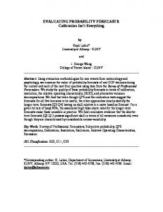
Abstract A large scale airborne experiment was performed in order to evaluate the visual detection performance of operators while using an advanced sensor system for Search and Rescue tasks. Such an evaluation is timely due to the Government of Canada’s intent to replace its aging Fixed-Wing Search and Rescue aircraft with a more advanced, sensor-equipped fleet. The experiment involved 22 hours of night time flight trials using an infrared sensor system performing a search pattern over an idealized trial range. Ninety search objects resembling downed, fixed wing, general aviation aircraft were placed within a 21 km by 13 km grassland area to compose the trial range. The rate of detection was found to be 81.8% based on 978 total detection opportunities, across two sensor operators. 1.0 Introduction The Government of Canada has committed to replacing its aging Search and Rescue (SAR) fleet of aircraft. The intent is to replace the 50 year old CC115 Buffalos and some of the CC130 Hercules with a more advanced, sensor-equipped fleet (Canada. Department of National Defence, 2015). For this reason, there is a need to evaluate the detection performance of operators while using an advanced sensor system for night time Search and Rescue (SAR) tasks. This paper outlines an experiment led by the National Research Council Canada (NRC) in collaboration with the Department of National Defence (DND) with funding from the National Search and Rescue Secretariat (NSS) SAR New Initiatives Fund. The experiment entailed evaluating the probability of detection using an airborne multi-sensor system for search and rescue operations. Multiple night time flights were performed with a sensor operator searching for artificial search objects that simulated downed aircrafts. The combined effectiveness of the sensor system with the operators in the loop was evaluated in the form of rates of detection. This paper outlines the method and data analysis procedures used in the study along with the final results. It should be noted that there was a night vision goggles (NVG) component to this project, but those results will not be addressed in this paper. 2.0 Method 2.1 Trial Range A trial range was created on the DRDC Experimental Proving Ground (EPG) at Canadian Forces Base Suffield. The range was approximately a 21 km by 13 km rectangular plot of land in the Southern Alberta grasslands. The vegetation on the range was mainly low-lying grasses typical of the Canadian prairies. Both natural and man-made objects were dispersed throughout the range prior to the placement of the experimental objects. These other objects included items such as gas wellheads, buildings, vehicles, and wildlife. Figures 1 through 4 below show some of these objects and a search object in the sensor display.
1
FIGURE 1: GAS WELLHEAD THROUGH INFRARED SENSOR
FIGURE 2: WILDLIFE (COWS) THROUGH INFRARED SENSOR
FIGURE 3: BUILDINGS THROUGH INFRARED SENSOR
FIGURE 4: SEARCH OBJECT THROUGH INFRARED SENSOR
2.2 Flight Routes The desired sensor configuration determined the flight routes which replicated a track crawl SAR mission. A track crawl SAR mission entails flying in-line with, or on either side of, a search object’s intended track (Department of National Defence; Canadian Coast Guard, 1998). These key parameters and their desired values for the trial are listed in Table 1 below. It is important to note that the chosen routes were not planned to cover the entire trial range, but rather only specific tracks within in it. Fifteen flight lines oriented roughly East-West with 1900 m separation in between were found to fulfill the desired configuration. Four unique flight routes composed of differing sequences of these same 15 flight lines were specified as illustrated in Figure 5. A random route was designated for each trial night flight. This variation of flight routes was implemented in order to limit learning; in other words, to limit the sensor operator’s familiarity with the arrangement or location of the search objects throughout the trial range. There were a total of 11 trial flights as listed in Table 2 below.
2
TABLE 1: KEY PARAMETERS FOR TRIAL
Parameter Groundspeed Altitude (above ground level) Slant Angle Sensor Vertical Field of View Sensor Horizontal Field of View Percent Overlap of Consecutive Flight Legs
TABLE 2: TRIAL FLIGHT DATE AND ROUTE BREAKDOWN
Value 100 ±20 kts 1500 ±100 ft 30° 18.18° 13.63° -200% (negative meaning that the legs do not overlap but rather have uncovered area between)
Flight
Date
Route
1 2 3 4 5 6 7 8 9 10 11
September 15, 2014 September 16, 2014 September 17, 2014 September 18, 2014 September 19, 2014 September 22, 2014 September 24, 2014 September 25, 2014 September 28, 2014 September 29, 2014 September 30, 2014
4 4 2 3 1 3 4 1 2 3 4
FIGURE 5: FLIGHT ROUTES. "S" AND "E" INDICATE THE ROUTE START AND END, RESPECTIVELY.
2.3 Search Objects The range was created with 90 objects arrayed along the flight lines shown in Figure 5. The objects comprised aluminized polyethylene blankets arranged to resemble either a crashed general aviation aircraft (for example, a Cessna 172) or a slightly different aircraft-shaped distractor of equal surface area1. The aluminized polyethylene search objects were analyzed to ensure they produced similar emissivity to the aluminum used for most aircraft. Sixty of these objects (see Figure 6) were placed in configuration 1 (replicating a general aviation aircraft) while the remaining 30 were placed in configuration 2 (slightly different from configuration 1 for a subsequent discrimination task that will be reported upon separately). 1
The impact of the different shaped objects on detection and discrimination will be addressed in subsequent work.
3
The objects, with 25.45 m2 surface area, were secured to the ground with clips and wooden stakes following regulations in place at the EPG (see Figure 7).
FIGURE 6: SEARCH OBJECT CONFIGURATIONS
FIGURE 7: PLACEMENT OF CONFIGURATION 1 OBJECT WITH WOODEN STAKES AND CLAMPS
The location of the search objects was determined randomly with the constraint that they must lay within the sensor view on one of the 15 flight legs and successive objects would be separated by at least 1253 m (two times the sensor field of view vertical length). On each trial flight, all of the 90 search objects would be visible if the sensor was at maximum field of view, pointed down the flight lines at a 30° slant angle while flying at 1500 ft above ground level (AGL). There were a few “exclusion zones” within the EPG where objects could not be staked into the ground, so none were placed there. Figure 8 illustrates the placement of the search objects outside of the exclusion zones but inside the flight line sensor view boundaries.
FIGURE 8: OBJECT PLACEMENT, EXCLUSION ZONES, AND SWEEP BOUNDARIES WITHIN TRIAL RANGE
2.4 Equipment The sensor system used in the trial was the Advanced Integrated Multi-sensing Surveillance (AIMS) system which was developed as a technology demonstrator by Defence Research and Development Centre (DRDC) Valcartier and its partners. The system was developed primarily for Search and Rescue, with an emphasis on functionality under low-visibility and low-light conditions. The AIMS system comprises a sensor turret and an operator station. The sensor package is a L3-WESCAM MX-20 turret 4
with an active imager (AI), a 3-5 micron infrared (IR) camera, a narrow (EON) and a wide (EOW) field of view electro-optical (EO) camera (Lechevin, Larochelle, Roy, Likuski, & Rea, 2013). The main workstation controls for the system are a joystick for the sensor control (orientation, zoom, etc.) and keypads, switches, knobs, and scroll wheels for setting various configurations of the sensor package. The AIMS system is described in detail in Lechevin et al. (2013) and the development of the interface design is described in Baker and Youngson (2007). The NRC’s Twin Otter aircraft was modified to carry the AIMS system. The turret deployed from the undercarriage of the NRC Twin Otter and the operator console installed within the cabin are depicted in Figures 9 and 10, respectively.
FIGURE 9: AIMS SENSOR TURRET DEPLOYED FROM TWIN OTTER
FIGURE 10: AIMS SYTEM OPERATOR STATION WITHIN TWIN OTTER CABIN
2.5 Participants Two operators were required to perform separate trial tasks on alternating test nights. Few people have experience with the specific sensor used for these trials. Two male Canadian Forces Airborne Electronic Sensor Operators (AESOPs) were made available, one with and the other without significant experience with the sensor system. Also worth noting is that the inexperienced AESOP had very limited prior flight experience with any EO/IR sensor, whereas the experienced AESOP had significant experience with multiple system types. Furthermore, the experienced operator was older (mid-40s) than the inexperienced operator (mid-20s). 2.6 Experimental Procedure After local astronomical twilight, the NRC Twin Otter departed towards the trial range. It was ensured that the search task did not begin before or during twilight to limit the amount of reflectance from the aluminized objects and emulate a true night-time search task. The trial range was chosen to be well away from large artificial light sources such as that created by a city. Reflectance from artificial light sources was undesired because the experiment attempted to replicate typical SAR scenarios in which aircraft have crashed far away from artificial light sources. Inside the Twin Otter cabin, one AESOP took position seated at the AIMS operator station, an experimenter sat next to the AIMS operator to record observations, and the other AESOP carried out an NVG task that will be reported separately. The AESOPs alternated tasks each trial flight. That is, if the experienced AESOP was the AIMS operator on the first trial flight, he would then carry out the NVG 5
search task on the second trial flight, while the inexperienced AESOP operated the AIMS system. This alternation was another way to help minimize the operators’ familiarity with the pattern of targets within the range. Each AESOP was given training on one full flight prior to the trial flights. The pilot flew the planned routes attempting to maintain straight flight lines at 100 ± 10 kts groundspeed, 1500 ± 100 ft above ground level. The task for the sensor operator was to fix the sensor view directly down the flight line with a 30° slant angle at maximum field of view. The AESOPs were instructed to carry out the task in this manner in order to minimize performance variability which could arise from differences in operator training and scanning techniques, as in a similar U.S. Coast Guard (USCG) study (Hover, Mazour, Osemer, & Nash, 1982). Although it was possible to use a preset sensor configuration to accomplish this under optimal conditions, fixing the sensor directly down the flight line with a 30° slant angle was an entirely manual task when the aircraft was angled into a crosswind to maintain its path down the flight line, which occurred regularly. When the AESOP detected a search object, they were required to verbalize the detection, identify the object as either configuration 1 or configuration 2, and also take a “Target Capture” using the AIMS system. A target capture was a simple button press that saved digital images of all of the sensor outputs and created a metadata text file containing aircraft and sensor data at the time it was pressed. Detections from the sensor operator were recorded by four means. The target captures provided a major source for detection validation with images and metadata for each instance. Secondly, the experimenter recorded if the AIMS operator detected a search object and whether or not they were able to discriminate the object between configuration 1 and configuration 2. The AIMS sensor video combined with headset audio was recorded as the third means to validate detection through post-trial review. Lastly, two video cameras mounted within the cabin recorded the AIMS operator actions, headset audio, and the aircraft GPS position. 2.7 Physiological Monitoring The AESOPs physiological conditions were monitored throughout the trial. Further information, including the results, of the physiological component of this study can be found in Berezny et al. (2015). 2.8 Data Analysis The goal for the data analysis was a validated set of detections and misses for all of the trial flights. The first step was collating the results of detections from the sheet that the experimenter at the AIMS station completed for each trial flight. These results were preliminary and not validated but gave structure to the subsequent analyses. Completed experimenter sheets were available for all flights, but as post processing revealed, there were occasional errors present in the data recorded by the experimenter because they could not always confirm the AESOP’s responses in-flight. Further analysis included using the metadata and image data from the target captures to validate detections or non-detections (misses). The image metadata provided the latitude and longitude position of the centre of the sensor view. The experimenter’s results could be validated if there was an image captured with a search object in view. Occasionally, the target captures resulted in unclear images that were not viable for detection validation. In this case, the metadata of the sensor’s frame centre latitude and longitude could provide an estimate of whether a target was indeed visible, but the video recordings
6
would have to be used for validation. Target capture data was available for all flights; however, on a few occasions the operator verbalized detection but failed to properly press the target-capture button. Furthermore, the most robust method used to validate the detection results was the audio and video recordings from the AIMS system and the aircraft headsets. The video recorded from the AIMS system was the video output of the sensors; the same video displayed on the system’s monitors. All of the verbal communication through the aircraft headsets was recorded on the video’s audio stream. AIMS sensor video data was not available for the night of September 20th due to a data downloading error, and the recording was not initiated until midtrial on September 28th due to a procedural error so the audio and video recordings were also not a complete data source. The AIMS system displays and records four video channels: IR, EON, EOW, and the video-in-command (VIC). The VIC consisted of a chosen sensor video stream with metadata in the form of aircraft latitude and longitude position, sensor frame centre latitude and longitude position, date and time, and more was overlaid on the sensor image as seen in Figure 11. Mainly, the IR video stream was used for the VIC but the operator could switch to another sensor stream, if required. The IR provided the most detail for the nighttime search task. In the process of reviewing all of the recorded AIMS audio and video, when the operator verbalized that he had detected a search object with the sensor, the reviewing experimenter could validate the detection by observing the object along with its latitude and FIGURE 11: TARGET CAPTURE OF A STILL FROM THE VIC VIDEO longitude in the VIC display. Finally, as previously stated, a fourth data source for validation was the video and audio recorded with two video cameras recording the AIMS operator within the cabin. The cameras recorded aircraft GPS position, time, and headset audio. This data source was used similarly to the AIMS video data but was only used when the AIMS recordings were missing (Sept. 20th and 28th). 3.0 Results From the 11 trial flights there were a total of 978 detection opportunities. One flight was cut short due to system difficulties resulting in the absence of 12 detection opportunities for that trial. Otherwise, each trial flight had 90 detection opportunities as planned. With a total of 800 validated detections and 178 validated misses, the AESOPs were able to achieve an 81.8% overall detection rate. Table 3 below shows that the experienced and inexperienced AESOPs performed similarly. TABLE 3: DETECTION RESULTS BY AESOP
AESOP Experienced Inexperienced Total
Total Detections All Flights 442 358 800
Total Misses All Flights 98 80 178
Mean Detection Rate Over Trial Flights 81.9% 81.7% 81.8%
Standard Deviation Over Trial Flights 5.7 % 5.5 % 5.6 % 7
The AESOPs also performed similarly when the detection rates are viewed versus trial flight number as plotted in Figure 12. The mean detection rates and standard deviations for each AESOP across the 11 trial flights are also presented in Table 3 above. Experienced AESOP
Inexperienced AESOP
8
9
83%
7
86% 74%
4
74%
3
60%
76%
87%
2
77%
84%
1
89%
84%
Detection Rate
80%
84%
100%
10
11
40%
20%
0% 0
5 6 Trial Flight Number
FIGURE 12: AESOP DETECTION RATES VERSUS TRIAL FLIGHT NUMBER
4.0 Discussion The observed detection rate indicates that a sensor system can be a useful tool for night time SAR operations. This preliminary analysis of an idealized search task is a valuable and promising start to understanding the capabilities of human-operated EO/IR sensors in a SAR role. The high detection rates may also be attributed to factors other than the success of sensors in a night time SAR role. The search objects were contrasted highly with the background providing targets that were typically quite salient. Since the search objects were, for the most part, as visible as they appear in Figures 4 and 11, the detection rates may be higher than with actual downed aircraft. Figure 13 illustrates the effect that different background conditions (for example, moisture content, vegetation type, etc.) can have on the visibility of possible search objects and thus detection rates. Secondly, the trials were flown at the low altitude of 1500 ft. This low altitude meant that the Cessna 172-sized search objects occupied a larger amount of the sensor field of view than would be the case at a higher altitude. These low altitudes likely contributed to the high detection rates. Thirdly, there were a large number of search objects throughout the range (see Figure 8) with an average of 6 per 21 km (approximately 6 minutes, 50 seconds at 100 kts) flight line. This high number was chosen in order to permit a consistent detection rate estimate across a large number of targets. High frequency of search objects over time is associated with higher rates of vigilance (Baddeley & Colquhoun, 1969). Thus, the large number of search objects may have helped the operators maintain a high level of vigilance throughout the flight. By avoiding a vigilance decrement with the high object rate used in this trial, the detection rates may be significantly higher than for tasks with fewer detection opportunities. Of course, vigilance may also be influenced by the presence of a reward or knowledge of results relating to detected signals or search objects (Sipowicz, Ware, & Baker, 1962). Neither explicit rewards nor knowledge of results were provided during this study but in a real SAR 8
mission, the reward of saving lives or knowing that a detected object was indeed a downed aircraft would act to maintain vigilance as suggested in Sipowicz et al. (1962).
FIGURE 13: TWO SEPARATE IMAGES OF THE SAME LOCATION AND SEARCH OBJECT THROUGH THE INFRARED SENSOR. THE SEARCH OBJECT IS VISIBLE ON THE RIGHT BUT NOT VISIBLE ON THE LEFT. (IT SHOULD BE NOTED THAT THE IMAGE ORIENTATIONS ARE DIFFERENT BUT THE LOCATIONS ARE THE SAME.)
The search objects degraded over time due to their limited design and the presence of roaming wildlife on the range. This degradation resulted in incomplete search objects as illustrated in Figure 14. The degraded search objects had less surface area than the complete, but the degradation did not appear to have an effect on detection rates as shown by the sustained rates over the trial flights in Figure 12. The effect of this degradation will also be further analyzed in subsequent work. A further study by the NRC will look to better understand the relationship of detection rates to search object visibility in IR sensor outputs. The study entails displaying images with varying levels of contrast between the search objects and the surrounding area. This will help to understand how different search objects with lower visibility or contrast to background might influence detection rates. FIGURE 14: DEGRADED SEARCH OBJECT
This large scale study complements prior independent studies by DND and USCG. DND had previously found that search sensors, specifically the AIMS system, had the potential to be valuable tools for SAR (Lechevin, Larochelle, Roy, Likuski, & Rea, 2013). However, DND’s evaluations were limited in the number of search objects and total detection opportunities, so this present study somewhat fills the need for a more statistically robust evaluation. On the other hand, USCG’s evaluations were performed with helicopters over water (Hover, Mazour, Osemer, & Nash, 1982) to observe the effects that various conditions (for example, sea state, altitude, search object type, etc.) had on detection. However, in this present study conditions were not varied in the evaluation of search sensor capabilities over land.
9
5.0 Conclusion The findings of this preliminary study have demonstrated that the use of an advanced, aircraft-mounted sensor can result in high detection rates for idealized SAR scenarios in which high contrast targets are located in mainly dry and flat grassland. It is promising for sensors in this role that with over 22 hours of flight data collection, the rate of detection was found to be 81.8% based on 978 total detection opportunities. This paper describes an evaluation of probability of detection using an airborne multisensor system for search and rescue operations. Future studies will be required to examine the utility of airborne sensing systems under other conditions, such as for searches involving different altitudes, groundspeeds, terrain types, groundcover, seasons, and/or object types. Nevertheless, this study does provide promising results indicating that sensors may become an important tool in finding survivors in airborne search and rescue missions conducted over land. 6.0 Acknowledgements This study was funded in part by the National Search and Rescue Secretariat, and in part by the NRC Working and Traveling on Aircraft Program. The AESOPs who took part deserve much appreciation for their eager assistance and cooperation throughout the month-long trial period. Jim Thoreson and other Civil Air SAR Association (CASARA) volunteers were kind enough to donate their time to assist with the set-up of the experiment. Similarly, Stéphane Messier and Terry Rea of Defence Research and Development Canada – Valcartier provided their expertise and were instrumental for the success of the trial. Captain Michel Gosselin, DND, and George Leblanc, NRC, merit praise for managing the project. Also, Madeline Lee, Paul Kissmann, Angela Gagnon, and Graham Payne of the NRC worked tirelessly in support of this project.
References Baddeley, A. D., & Colquhoun, W. P. (1969). Signal probability and Vigilance: A Reappraisal of the 'Signal-Rate' Effect. British Journal of Psychology, 60(2), 169-178. Baker, K., & Youngson, G. (2007, June). Advanced Integrated Multi-sensor Surveillance (AIMS). Mission, Function, Task Analysis. Retrieved April 10, 2015, from Defense Technical Information Center: http://www.dtic.mil/get-tr-doc/pdf?AD=ADA482576 Berezny, N. J., Craig, G. L., Lee, M., Wright, H. E., Thomas, R., Kissmann, P., & Keillor, J. M. (2015). A comparison of task-related phyisological responses in operators using EO/IR sensors or Night Vision Goggles to carry out air-to-ground search. Paper approved for publication. Canada. Department of National Defence. (2015, March 31). Fixed-Wing Search and Rescue Aircraft Replacement (FWSAR) Project: Request for Proposal (RFP) (CD-ROM) (Vol. 1). Ottawa, ON, Canada: FWSAR Secretariat. Department of National Defence; Canadian Coast Guard. (1998). National Search and Rescue Manual. Ottawa. Hover, G., Mazour, T., Osemer, S., & Nash, L. (1982, Sept. 20-22 ). Evaluation of forward looking infrared (FLIR) as a coast guard SAR sensor. OCEANS 82, 491-495. Retrieved from http://ieeexplore.ieee.org/stamp/stamp.jsp?tp=&arnumber=1151782&isnumber=25890
10
Lechevin, N., Larochelle, V., Roy, S., Likuski, K. A., & Rea, T. (2013, Summer). Advanced Integrated Multi-sensing Surveillance: Capabilities for Future SAR and ISR missions. The Royal Canadian Air Force Journal, Vol. 2(No. 3), 41-51. Sipowicz, R. R., Ware, J. R., & Baker, R. A. (1962). The Effects of Reward and Knowledge of Results on The Performance of a Simple Vigilance Task. Journal of Experimental Psychology, Vol. 64(No.1), 58-61.
11