ICSNC 2011 : The Sixth International Conference on Systems and Networks Communications
Evaluation of Adaptive Interference Cancellation in Chirp Spread Spectrum-based Communication Systems
Martin Brandl, Karlheinz Kellner Center for Biomedical Technology Danube University Krems Krems, Austria
[email protected],
[email protected] Abstract—For data transmission in heavily distorted indoor environments, chirp-based spread spectrum systems operating in the 2.45 GHz ISM band are well applicable. The robustness of spread spectrum systems against narrow band jammers is given by their compression gain, which is defined by the timebandwidth product of the spreading signal. Using chirp matched filter systems, jammers can pass through the receiver filter and are only weighted by its transfer function. Dividing the receiver chirp filter into time (equivalent to frequency) intervals, a jammer can be suppressed by switching off the corresponding frequency interval, leading to an increased jamming robustness. Due to its simplicity, this is suitable even for low cost systems. Theoretical and experimental results prove the capability of the method. Keywords—spread spectrum, chirp, matched filter, FPGA design
I.
INTRODUCTION
Nowadays, wireless communication systems employ digital modulation and advanced signal processing capabilities. Wireless transmission systems for short range applications are a fast growing topic in communication engineering. There are many fields of applications, from the transmission of speech and video in cordless telephone sets to high data rate communication in local area networks, for example. Low power devices (LPDs) for license free operation in the so-called industrial, scientific, and medical frequency bands/ISM (ISM bands are defined by the International Telecommunication Union—Radio Communication Sector /ITU-R in 5.138, 5.150, and 5.280) have been placed on the market. In particular, communication systems for wireless local area networks (WLANs) are targeted for applications in large indoor areas, offices with wiring difficulties, branch offices, and temporary indoor networks. WLANs are appropriate for unwired small business offices such as realestate agencies, where only a few terminals are needed and where there may be frequent relocations of equipment to accommodate reconfiguration or redecoration of the office space. Therefore, for wireless operation in local area networks, systems have been introduced especially for systems of micro- and picocells within buildings, including the option of roaming. Since an indoor environment with a dominant multipath propagation scenario [1] and unlicensed operation are difficult to beat using narrow band systems,
Copyright (c) IARIA, 2011.
ISBN: 978-1-61208-166-3
spread spectrum sets have been introduced [2]. They operate with direct sequence modulation with a spreading factor of approximately 10 or in frequency hopping mode with a limited number of channels. Such WLAN systems have succeeded in operation and number, respectively. The WLAN modulation, transmitted spectral distribution, media access control, interoperability, and so on are standardized in IEEE 802.11. For indoor environments, the coherence bandwidth is typically 2 to 5 MHz for the 2.45 GHz ISM band [3]. Therefore, the bandwidth of the transmission system should be at least two times the channel coherence bandwidth, resulting in narrow band communication systems which are difficult to operate in industrial environments. To overcome this problem, available spread spectrum systems for WLANs use approximately 20 MHz of the 83.5 MHz bandwidth allowed in the ISM band at 2.45 GHz. For indoor data communication, a broad band chirp spread spectrum system has been developed. II.
CHIRP-BASED SPREAD SPECTRUM SYSTEMS
Due to the large bandwidth covered in chirp spread spectrum systems, they show good resistance against selective fading due to multipath propagation. Increasing attenuation on the propagation path because of shadowing results in a decrease in received energy and raises the bit error rate. The influence of Rayleigh fading has been observed to be mostly insignificant for broad band spread spectrum systems. If strong jammers occur, most conventional systems are disturbed heavily. In spread spectrum systems, the signal to interference ratio (SIR) at the detector is increased due to the correlative signal processing gain. The "capability" of jammer suppression by impulse compression on a signal matched filter (MF) is given by the time-bandwidth product (T·B) of the spreading signal [2]. The upper limit for the total jammer power (in dB) within the signal spreading bandwidth is the SIR at the detector required for the minimum error probability minus the MF compression gain (T·B product) in dB. It must be considered that in the case of weighted chirps, which are typically used in communication systems to get a higher peak to side lobe ratio, the effective T·B product becomes smaller than without weighting, resulting in a reduced jamming resistance.
72
ICSNC 2011 : The Sixth International Conference on Systems and Networks Communications
The developed chirp spread spectrum data transmission system utilizes linear chirps for spread spectrum generation. A linear chirp is characterized by linear frequency modulation and can be divided into up-chirps where the angular frequency is increasing over time and down-chirps where the angular frequency is decreasing over time. Chirp signals are characterized by their start and stop frequencies which define the chirp bandwidth Bc and the time duration of the chirp signal Tc. The matched filter compression gain Gc of a chirp spread spectrum signal is therefore given by its time-bandwidth product Gc = BcTc. In our system, the effective T·B product was approximately 13.6 dB instead of the theoretical maximum of 19 dB (Tc = 2µs, Bc = 39 MHz, where fchirp_start = 1 MHz and fchirp_stop = 40 MHz; 10*log(TcBc) = 19 dB). The chirp signals are Hamming weighted, which reduces the compression gain by 5.35 dB in comparison to non-weighted signals [4]. Signal weighting raises the side lobe suppression by about 30 dB, which is necessary for a reliable intersymbol interference (ISI) reduction [4]. Our chirp-based data transmission system is based on binary orthogonal shift keying (BOK) where the data symbols are coded with up- and down-chirps [5]. In Figure 1 the principle of chirp BOK data transmission is illustrated. In the transmitter, a logical data symbol “1” is coded with an up-chirp signal and a logical data symbol “0” is coded with a down-chirp signal. Both chirp signals are orthogonal, which means that the cross-correlation function is approximately zero. The receiver consists of two matched filters corresponding to the transmitted chirp signals. In the case of a transmitted up-chirp, the up-chirp MF delivers the chirp autocorrelation function at the output with a compression gain Gc. At the same time point, the down-chirp MF delivers the chirp cross-correlation function, which is approximately zero. The reconstruction of the transmitted data symbols is done by a comparator circuit which compares the MF output amplitudes at each symbol interval.
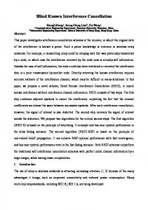
As discussed before, spread spectrum communication systems are robust against fading and jamming but there are clear limits given by the spreading bandwidth and the MF compression gain. To improve the robustness of chirp spread spectrum systems against jamming, which is mainly caused by microwave ovens and other communication systems operating in the same ISM band, we used gated chirps where the jammed chirp subband can be turned off. For linear chirp signals, in the time domain a certain signal interval of the chirp signal corresponds to a certain frequency interval in the frequency domain (Figure 2). In contrast to [5], where an analog implementation of gated chirps based on tapped SAW chip filters is presented, this paper deals with a fully digital chirp filter implementation. This offers several advantages especially in the fully flexible number of chip subbands as well as on the design of the implemented filter transfer function. S(f)
Jammer Chirp subbands
II
I 1MHz
III
14MHz
f 40MHz
27MHz
f(t) I
II
III
S(f)
t
Adaptive interference cancellation
Jammer II
III
f
III
t
Chirp subbands
f(t) Up-chirp (Bc=39MHz, Tc=2µs)
Chirp transmitter x(tn)=1
I
Data stream x(t)
x(tn)=0,1 ?
Down-chirp (Bc=39MHz, Tc=2µs)
+
II
Figure 2. Principle of adaptive interference cancellation by modification of the chirp MF.
x(tn)=0
Chirp receiver
Up-chirp MF yup(t) Data stream x’(t) Down-chirp MF
yup(tn) > ydown(tn) x’(tn)=1 yup(tn) < ydown(tn) x’(tn)=0 ydown(t)
Figure 1. Principle of chirp-based data transmission.
Copyright (c) IARIA, 2011.
ISBN: 978-1-61208-166-3
The chirp MFs are implemented by digital finite impulse response (FIR) filters. By changing the filter coefficients of the chirp MF the transfer characteristics in the corresponding frequency band can be modified (turned off). In Figure 2 an example is given where the chirp MF impulse response is divided into three subbands. The narrow band jammer is located in subband I and can be substantially suppressed by turning subband I off. By modification of the chirp MF for adaptive interference suppression (the MF bandwidth is reduced by 1/3), the MF compression gain is reduced in the given example by 3.4 dB. System simulations where the SIR on the transmission channel is adjusted to 0 dB, which means that the power of
73
ICSNC 2011 : The Sixth International Conference on Systems and Networks Communications
the jammer is equal to the power of the transmitted chirp signal, are shown in Figure 3. The frequency of the jammer is set to 5 MHz and therefore interferes with the chirp subband I. By gating off the corrupted frequency band, the jammer can be substantially suppressed as shown in Figure 3.
USA). The chirp receiver consists of an analog to digital conversion section with a sampling rate of 100 MSamples/s and two chirp MFs with adaptive switchable filter coefficients for interference suppression. Envelope detection is done by a square law demodulator and an FIR low pass filter.
a)
Mini Circuits Combiner ZFRSC-42-S+
D/A
NCO
1.4
Agilent 33250A Function Generator
TP Mini Circuits SLP-50+
1.2 TX-data
Mini Circuits ERA-4
Up/down controller
1 Amplitude [a.u.]
TX-clk
0.8 TP FIR filter
x2
Down-chirp FIR filter
TP FIR filter
x2
Up-chirp FIR filter
0.6 RX-data
Comparator
A/D
0.4
0.2
0
RX-clk
0
0.5
1
1.5
2 2.5 3 Frequency [Hz]
3.5
4
4.5
5 x 10
Pll
Filter coefficient control
7
Altera DSP-DEVKIT-2S60
b)
Figure 4. Principle of the chirp BOK data transmission system.
1.4
1.2
Amplitude [a.u.]
1
0.8
0.6
0.4
0.2
0
0
0.5
1
1.5
2 2.5 3 Frequency [Hz]
3.5
4
4.5
5 x 10
7
Figure 3. Suppression of a narrow band jammer at 5 MHz by adaptive interference cancellation (SIR = 0 dB).
A comparator circuit compares the amplitudes of the demodulated MF output signals and reconstructs the transmitted data stream. For data clock reconstruction a Pll circuit triggered by the reconstructed data symbols is used. Figure 5 shows the measured matched filter output signals after demodulation and filtering. Figure 5 depicts the MF autocorrelation function (compressed chirp signal) without (Figure 5a) and with (Figure 5b) adaptive interference cancellation. The pictures show three compressed chirp signals (MF autocorrelation function) followed by two crosscorrelation output signals in equidistant symbol time intervals of 2 µs. a)
b)
III. FULLY DIGITAL IMPLEMENTATION OF A CHIRP SPREAD SPECTRUM SYSTEM WITH ADAPTIVE INTERFERENCE CANCELLATION The chirp BOK system was implemented on an Altera DSP development kit (DSP-DEVKIT-2S60, Altera Corporation, USA) based on an Altera Stratix II FPGA. The complete hardware design is shown in Figure 4. The chirp generation is done by a numerically controlled oscillator (NCO). After subsequent digital to analog conversion and low pass filtering (fg = 50 MHz) the chirp signals are fed into a 50 ohm coaxial transmission line. The generated chirp signals have a start frequency of 1 MHz, a stop frequency of 40 MHz (Bc = 39 MHz), and a time duration of 2 µs. To compensate the power loss of the combiner circuit, a monolithic RF amplifier (ERA-4, Mini Circuits, USA) is used in the transmission link. A sinusoidal jammer is generated by a function generator (33250A, Agilent, USA) and is fed into the transmission channel by a power combiner (ZFRSC-42-S+, Mini Circuits,
Copyright (c) IARIA, 2011.
ISBN: 978-1-61208-166-3
Figure 5. Matched filter output signals after demodulation: a) without chirp gating, b) with adaptive interference cancellation (fjammer = 5 MHz, SIR = –6dB).
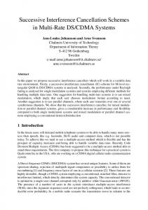
The performance of the chirp data transmission system is evaluated by its bit error rate (BER) in different jamming situations (Figure 6). BER measurement was done by a selfdesigned BER tester based on the IC DS2172 (Dallas Semiconductor, USA). In general, the chirp BOK data transmission system yields a high jamming robustness. A remarkable BER was firstly measured for an SIR on the transmission channel below –2 dB. For lower SIR values, a
74
ICSNC 2011 : The Sixth International Conference on Systems and Networks Communications
steep increase in the BER to 10e-2 was found, mainly based on wrong decisions at the comparator circuit resulting in lost data bits and high jitter at the clock recovery circuit. Using adaptive interference cancellation by switching off corrupted chirp subbands, the system performance can be increased in SIR robustness by at least 4 dB (Figure 6). 1.E+00 1=on, 2=on, 3=on, fi=35MHz 1=on, 2=on, 3=off, fi=35MHz 1.E-01
1=on, 2=on, 3=on, fi=5MHz 1=off, 2=on, 3=on, fi=5MHz
BER
1.E-02
1.E-03
1.E-04
4dB 1.E-05
1.E-06 -14
-12
-10
-8
-6
-4
-2
0
2
4
6
8
SIR [dB]
Figure 6. Measured bit error rate in dependency on the SIR at the transmission channel with and without adaptive interference cancellation.
IV.
CONCLUSIONS
A chirp spread spectrum BOK data transmission system with adaptive interference cancellation was built. The whole design was fully implemented onto an Altera FPGA board. For selective jammer suppression, an adaptive interference cancellation principle based on gated chirps was shown. By switching off jammed chirp subbands the robustness against narrow band interference can be increased by at least 4dB. ACKNOWLEDGMENTS The authors would like to thank the government of Lower Austria and the European Regional Development Fund (EFRE) for their financial support of the project (Project ID: WST3-T-91/004-2006). REFERENCES [1] G. Prorakis, Digital Communications, 3rd ed. McGraw-Hill, 1995. [2] G.R. Cooper, C.D. McGillem, Modern Communications and Spread Spectrum, McGraw-Hill, 1986. [3] I. Paez, S. Loredo, L. Valle, R.P. Torres, “Measuring broadband radio channel parameters using a simple experimental set-up”, The 13th IEEE International Symposium on Personal, Indoor and Mobile Radio Communications, vol. 1, pp. 473 – 477, 2002. [4] C.E. Cook., M. Bernfeld, Radar Signals, Artech House, 1993. [5] M. Brandl, A. Pohl, F. Seifert, L. Reindl, “Fast adaptive interference cancellation in chirp spread spectrum systems “, IEEE Global Telecommunications Conference, 1999; Proceedings Vol. 4, Pages 2218 -2222
Copyright (c) IARIA, 2011.
ISBN: 978-1-61208-166-3
75