Evaluation of Electromagnetic Error Correction Methods Correcting Distortion Fields for Appliance in the Radiation Therapy Room Joerg Traub1 , Sukhbansbir Kaur1 , Peter Kneschaurek2 , Nassir Navab1 1 2
Chair for Computer Aided Medical Procedures (CAMP), TU Munich, Germany Radiation Therapy Department, Klinikum rechts der Isar, TU Munich, Germany Email:
[email protected]
Abstract. Electromagnetic tracking is currently the only available technology to track flexible instruments inside the human body without the use of real time imaging technology such as ultrasound or mobile c-arms. The limitation of electromagnetic tracking is its accuracy and sensibility to the environment, especially in the presences of ferromagnetic material and electronic devices. Navigation systems based on these technologies were recently introduced especially flexible endoscopy. One design goal for setting up such navigation systems is the removal of all material from the close environment that can perturb the magnetic field. In our scenario, within the radiation therapy room, we can not eliminate the gantry. Thus, existing methods for electromagnetic tracking error estimation and correction algorithms were reviewed, implemented, and adopted to the special requirement for navigation during prostate cancer treatment.
1
Introduction
Electromagnetic tracking systems are the only method to estimate the pose of flexible instruments inside the patient’s body without the use of imaging data. Navigation systems based on this tracking technologies were introduced for endoscopic procedures [1] and bronchoscopic interventions [2, 3]. One core requirement for image-guided medical procedures is high precision in the measured pose of objects, instruments and imaging devices. The pose estimation of objects with electromagnetic tracking system is highly dependent on the environment. Their sensitivity to the ferromagnetic metals and electronic materials that are in a close neighborhood of the field generator and/or sensors result in distortion of the reported pose. This is often referred to as tracking error. The tracking error could be reduced either by taking preventive measures or by corrective measures. Using preventive measures all materials that can perturb the electromagnetic field are eliminated from the close environment and replaced by equipment that does not affect the magnetic field. However, in several cases this is not practical e.g. in the radiation therapy room where it is not possible to remove the gantry. In
364
case those objects can not be eliminated from the environment the only solution is to evaluate the corrective measures in order to correct the tracking errors reported by the electromagnetic tracking system. This has to be done within two steps. Firstly, estimating the distortion field by sampling measurements with a more precise pose estimation system or with well known ground truth data grid. Secondly, applying the estimated error function in real time to the erroneous measurements. Several methods were introduced in the past for corrective measures for electromagnetic tracking systems [4, 5, 6]. Kindratenko [7] provides an overview and extensive summery of existing methods.
2
Methods
The corrective measures are based upon the estimation of electromagnetic field distortions followed by the compensation of tracking errors [7]. The distortion field is estimated by a set of correspondences of exact (true sensor pose) and distorted (measured or reported sensor pose) values. These correspondences are stored in a lookup table. In this work a sampling lattice (indirect method) is used for the collection of the lookup table similar to the methods introduced by Bryson [8] and Zachmann [5]. In a second step the measured tracking pose is corrected in real time by the means of interpolation using this previously created displacement field (lookup table). Two different interpolation schemes have been implemented and evaluated. The first method is a local approach based on trilinear interpolation [8]. The second method is based on a global interpolation schemes [9]. The effects of certain parameters on the correction accuracy by the global interpolation scheme have been assessed and are discussed in the results. The electromagnetic tracking system was physically mounted within the radiation therapy room in a close distance to the gantry. It was placed such, that the tracking volume covered the entire abdominal area of the patient.
3
Results
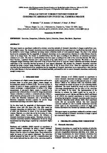
The lookup table collection procedure using sampling lattice is accurate and simple both in terms of apparatus and computation, but time consuming for building larger 3D lookup tables (7-12 minutes for 121 points within 10cm2 ). Out of the two position error correction methods for magnetic tracking system, the correction method based on the global scattered data interpolation has proved to be better in terms of accuracy (97%)(see figure 1), smoothness of interpolant function and flexibility of arrangement of lookup table data. The method was tested in the radiation therapy environment with the gantry as a not removable source of distortion. The mean error after the application of local and global method is improved by 89.9% and 97.2% respectively (see figure 2). The correction performed with the global method is independent of the separation distance of the sensor from the transmitter and the local distortion of the magnetic field. For the local method, it varies from 4mm-21mm at different positions and for global
365 Fig. 1. Error metrics before and after correction. On x-axis, the method applied is specified. None corresponds to the uncorrected values. On y-axis, error metrics mean error, maximum error, minimum error and standard deviation are plotted in millimeters. Standard deviation is plotted as a bar that shows the limits for deviation from a measured value
method it is within 4mm at all positions. However, the correction provided by the global correction method depends on certain parameters. The optimal parameter selection and preconditioning of the distortion function (in some cases) is required and has a crucial influence on the error correction.
4
Conclusion and discussion
Global correction method was proved to be better in terms of accuracy, flexibility in the collection of data for distortion estimation, and ease of operation. The current work has shown that electromagnetic tracking errors could be corrected adequately. With the implemented methods we show an improvement of 97% in the radiation therapy environment with magnetic field generator mounted close to the gantry. Medical applications especially where flexible instruments are tracked with electromagnetic tracking systems can benefit from this error correction. Special evaluation need to be performed before applying the correction methods in each distingt environments to provide the best and most accurate available tracking results for each scenario and adjust the parameters of the correction. Further studies within the correction of electromagnetic field distortion will be conducted in the direction of a more feasible ground truth collection using a second, more accurate, tracking system (e.g. optical tracking). We discussed only the possibility of corrective measures by means of a not
366 Fig. 2. Vector field view of the correction. Ground truth values (blue asterisk), corrected values with trilinear interpolation method (red asterisks) and corrected values with HMQ method (magenta asterisks) are plotted in the yz plane of the tracking system coordinate system as shown in the plot of axes
alternating distortion field dynamically. An extension will be to integrate additionally a system to detect changes in the environment in real time to ensure the safety and robustness of navigation system based on electromagnetic tracking. A complete integration of all there error detection and correction approaches will be the fundamental technology to enable accurate, safe, and reliable navigation, especially during procedures with flexible instruments.
References 1. Guiraudon G, Moore J, Jones D, et al. Augmented reality for closed intracardiac interventions. In: International Workshop for Augmented Environments for Medical Imaging and Computer-aided Surgery (AMI-ARCS); 2006. 2. Hautmann H, Schneider A, Pinkau T, Peltz F, Feussner H. Electromagnetic catheter navigation during bronchoscopy: Validation of a novel method by conventional fluoroscopy. Chest 2005;128:382–387. 3. Solomon SB, Jr PWhite, Wiener CM, et al. Three-dimensional CT-guided bronchoscopy with a real-time electromagnetic position sensor: A comparison of two image registration methods. Chest 2000;118:1783–1787.
367 4. Livingston MA, State A. Magnetic tracker calibration for improved augmented reality registration. Presence: Teleoperators and Virtual Environments 1997;6(5):532– 546. 5. Zachmann G. Distortion correction of magnetic fields for position tracking. In: Procs Computer Graphics International; 1997. 6. Ikits M, Brederson JD, Hansen C, Hollerbach J. An improved calibration framework for electromagnetic tracking devices. IEEE Virtual Reality 2001. 7. Kindratenko VV. A survey of electromagnetic position tracker calibration techniques. Virtual Reality: Research, Development, and Applications 2000;5(3):169– 182. 8. Bryson ST. Measurement and calibration of static distortion of position data from 3D trackers. Procs SPIE 1992;1669:244–255. 9. Hardy RL. Multiquadric equations of topography and other irregular surfaces. J Geophys Res 1971;76:1905–1915.


![[PDF] Error Correction Coding: Mathematical Methods ... - Google Sites](https://m.moam.info/img/260x300/pdf-error-correction-coding-mathematical-methods-g_6477aa85097c47a9708bf774.jpg)