Author manuscript, published in "IEEE Transactions on Automation Science and Engineering, 99 (2012) 1" DOI : 10.1109/TASE.2011.2174357 1
Evaluation of Telerobotic Shared Control Strategy for Efficient Single-Cell Manipulation
hal-00643166, version 1 - 20 Dec 2011
Jungsik Kim, Hamid Ladjal, David Folio, Antoine Ferreira, Member, IEEE, and Jung Kim, Member, IEEE
Abstract—Microinjection using a glass capillary is a highly efficient method for the delivery of exogenous materials into cells and is widely used in biomedical research areas such as transgenics and genomics. However, this direct injection is a time-consuming and laborious task, resulting in low throughput and poor reproducibility. Here, we describe a telerobotic shared control framework for microinjection with high manipulation efficiencies, in which a micromanipulator is controlled by the shared motion commands of both the human operator and the autonomous controller. To determine the optimal gains between the operator and the controller, we proposed a quantitative evaluation method using a model of speed/accuracy trade-offs in human movement. The results showed that a 40–60 % weighting on the human operator (or the controller) produced the best performance for both speed and accuracy of task completion suggesting that some level of both automation and human involvement is important for microinjection tasks. Note to Practitioners—In single-cell microinjection, for the small size and delicate structure of a cell, to date, most human operators have manipulated biological cells manually; therefore, low manipulation efficiency and poor reproducibility has been reported for this task. Most manipulation systems have primarily focused on limited visual feedback in conjunction with a dialbased console system, requiring extensive operator training to perform injection tasks with reproducible results. To address these problems, a telerobotic shared control method for microinjection was developed by integrating the automatic and direct manipulation functions of a robotic system. While a controller retains cells and glass pipettes within a desired path or space, the operator can concentrate on the injection task, thus achieving high throughput and dexterity. Index Terms—Fitts’ and steering laws, microrobotic control, single-cell microinjection, telerobotic shared control.
I. I NTRODUCTION HE highly efficient transfer of foreign materials into cells remains a challenge in biotechnology, both for fundamental cellular and molecular biology research and in biomedicine. Several methods have been developed for the successful delivery of exogenous materials into cells. Among
T
This research was supported by Basic Science Research Program through the National Research Foundation of Korea(NRF) funded by the Ministry of Education, Science and Technology(2010-0022871). J.S. Kim is with the Department of Mechanical Engineering, Korea Advanced Institute of Science and Technology (KAIST), Daejeon, 305-701, Korea (e-mail: js
[email protected]) H. Ladjal, D. Folio, and A. Ferreira are with Institut PRISME, ENSI de Bourges, 88 Boulevard de Lahitolle, 18020 Bourges, France (e-mail: {hamid.ladjal, david.folio, antoine.ferreira}@ensi-bourges.fr) J. Kim is with the Department of Mechanical Engineering, Korea Advanced Institute of Science and Technology (KAIST), Daejeon, 305-701, Korea (phone: +82-42-350-3231; fax: +82-42-350-5230; e-mail:
[email protected])
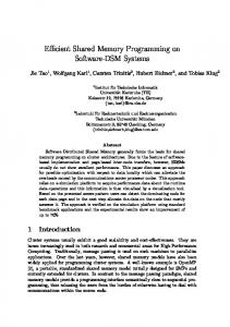
them, single-cell microinjection is performed to directly introduce foreign materials, such as DNA, proteins, sperm and drugs, into individual cells [1]-[3], and it is a relatively more efficient delivery method than electrical [4], viral [1], chemical [1], and other transfer methods [5], [6]. Microinjection is used in many different biotechnologies such as cell transfection with DNA in mammalian cells [1], induced pluripotent stem (iPS) cell transfer [7], and in vitro fertilization (IVF) by intracytoplasmic sperm injection (ICSI) [8], [9]. However, although microinjection has relatively high delivery efficiencies, the injection task is time-consuming and labor-intensive work that limits the manipulation of large numbers of single cells [1], [2]. The elaborate manipulation of small, delicate cells demands certain technical requirements, such as the development of micro-motion stages and the fabrication of micro-pipettes with a fine tip. In addition, great manipulation skills are required of a human operator requiring extensive training to perform these injection tasks; thus, microinjection has low manipulation efficiencies, resulting in low throughput and poor reproducibility. The manipulation of micrometer-sized cells is currently hindered by the limited capability of sensing technologies. These manipulations are often performed with insufficient visual information, within a small field of view and a narrow depth of field, creating a difficult situation for the detection and positioning of cells or glass pipettes. In addition, there is no force/tactile feedback for robot control or haptic interaction. Insensate glass pipettes can easily damage themselves or the target cells. To address these problems, several single-cell microinjection systems have been proposed to improve the manipulation efficiency. Automated microinjection systems have been developed to remove human involvement from the injection process [10]-[16], where a visual servoing approach is usually used to control the position and force of a micromanipulator; however, it is challenging to create a fully automated manipulation system because microinjection is conducted under diverse and complex conditions such as varying cell size (from one micrometer to hundreds of micrometers), cell types (e.g., suspended or attached ones) and liquid environments. Fig. 1 compares the various cells typically manipulated in many research and clinical fields, showing that the differences in the geometry and the material properties are greater than one-thousand-fold and one-million-fold, respectively. Therefore, there are difficulties in the dexterous manipulation of cells with multiple degrees of freedom (DOF) and in target selection (e.g., cell nucleus or cytoplasm) in visual servoing [17], [18]-[20]. Teleoperated microinjection systems have been developed to provide haptic feedback during manipulation
2
Diameter (μm) Bovine oocyte/embryo
Primary porcine aortic endothelial cell Barrett’s esophagus cell
Ovine oocyte/embryo Sea urchin oocyte/embryo Euplote Chinese hamster ovarian cell
Cervix epithelial hela cell Human primary neuron
Human oocyte/embryo
Human breast cancer cell Mouse oocyte/embryo Single human erythrocyte cell
Yeast cell 10
Zebrafish zygotes
0
10
1
10
Porcine oocyte/embryo
2
10
3
Elastic modulus (Pa) Melanoma
Human oocyte/embryo Normal epithelial cell
Fibroblast Outer hair cell
Cardiac myocyte Bovine oocyte/embryo
Neutrophils Aortic endothelial cell
Mouse oocyte/embryo
Zebrafish zygotes
Sea urchin oocyte/embryo 10
hal-00643166, version 1 - 20 Dec 2011
Fig. 1.
2
10
3
10
4
10
5
S. Cerevisiae
10
6
10
7
10
8
10
9
A comparison of sizes and mechanical properties of various cells [3], [5], [7], [10], [15], [32]–[46].
[21]-[25]. However, most of them have provided force sensing and feedback for only a small number of DOF. Here, we present a telerobotic shared control (TSC) framework developed for single-cell microinjection with high manipulation efficiency. The motivation of the TSC arose from the idea that the collaboration of a human and a robotic system can increase the quality and capability of manipulation by exploiting a human’s ability to skillfully manipulate objects with dexterity and disturbance adaptation along with a robot’s accuracy and repeatability [26]-[28]. To reduce the difficulties in biomicromanipulation mentioned above and simultaneously achieve high throughput and dexterity, both automatic and direct manipulation functions of the system are needed in microinjection. In the TSC approach, a human operator can control the manipulator as much as possible while a controller retains cells and glass pipettes within a desired manipulation path or space to provide adequate performance. In the remainder of this paper, the TSC strategy is first presented, and the sharing method for the teleoperation and automation modules of the microinjection system is described. In addition, we provide a quantitative analysis to determine what level of automation (or direct manipulation) is needed for optimal TSC. Most previous studies on shared control have not addressed how to determine the degree of autonomy (or human involvement) to implement in the telemanipulation for the best performance. Although shared control has been applied to various applications [28]-[31], this work is, to the authors’ knowledge, the first providing an evaluation method for determining the optimal shared control gains and the first application of shared control in a cellular micromanipulation. This work focused on the evaluation of a shared control for microinjection using the proposed model with Fitts’ and steering laws. II. M ETHOD A. Telerobotic Microinjection System Design A microinjection task consists of guiding a micropipette to a cell, puncturing the cellular membrane, and depositing foreign
CCD camera Microscopic lens with light source Holding glass micropipette
Micromanipulator Z Y X
Micromanipulator
Syringe picopump Pneumatic pump
Injection chamber
Glass micropipette
Vibration isolation table
Fig. 2.
Schematic view of micromanipulation system for microinjection.
materials at a targeted position. The cells in the injection chamber with a liquid medium are attached to a substrate or suspended by a second (holding) glass pipette. The pipette tip is angled to approach a cell in a liquid medium. The telerobotic biomicromanipulation system for microinjection consists of a master robot to input the operator’s motion command, micromanipulators with glass micropipettes and a vision system (Fig. 2). The task space of the master robot is represented by the coordinate frame {M : (x, y, z)} ∈ ℜ3 , the task space of the micro manipulator is represented by the coordinate frame {S : (X,Y, Z)} ∈ ℜ3 , and the image space of the fixed camera is defined by the image coordinate frame {I : (u, v)} ∈ ℜ2 . Visual information is a main sensing modality in the biomicromanipulation tasks. The processing of visual data determines the focal plane and the guidance path of the pipette tip within the image frame. In this study, because the input of the manipulator is given in the slave frame {S}, the mapping between {S} and the image frame {I} forms a critical component for servoing the pipette tip. To compute this mapping, a calibration methodology was developed and implemented. Several calibration methods exist in the literature and are mostly used in macroscale vision applications [47]. Unfortunately, those methods cannot be directly applied to calibrate an optical microscope due to the characteristics
3
45
Shared controller Human operator
Maximum pixel gradient magnitude
40
αp
uh
Kh Su
uc
35
Position controller
APF
25
Planner
20
Fig. 4.
Micro manipulator
Sp
Kc
30
TSC block diagram.
15 10 5
S
0
20
40
60 Z (µm)
80
100
120
Fig. 3. Maximum pixel gradient magnitudes along the center line of the tip image for different Z-depths.
hal-00643166, version 1 - 20 Dec 2011
Mp
of the optical system (e.g., high optical magnification and very narrow depth of field), and some dedicated methods have, therefore, been proposed [48]. In this work, the camera calibration parameters are defined in the focal plane (image space); therefore, the non-sharp tip image, due to the depth directional motion of the robot, is ignored. For an orthographic camera projection model, the tip position S p = (X,Y, Z)T in the slave frame can be related to its position I p in an image space as follows: ( ) (u) X/S + u u 0 I p= = (1) v Y /Sv + v0 where Su and Sv are the pixel dimensions (µ m/px) and the initial tip position I p0 = (u0 v0 )T is measured by the templatematching method in the focal plane [25]. When assuming an accurately position-controlled micromanipulator and an orthographic projection model, it is important to initially locate the tip in the focal plane. In this work, the precise placement of the tip along the Z depth is achieved by the comparison of the pixel gradient magnitudes at the tip because the tip is angled and has pure translational motion. The gradient magnitudes are computed along the center line in the u direction of the tip, and the maximum values for each Z depth are compared. The gradient magnitude is at a maximum when the tip is in the focal plane (Fig. 3).
u = Kh uh + Kc uc Kh + Kc = 1 0 ≤ (Kh , Kc ) ≤ 1
(2)
where Kh and Kc are the weighting factors for the operator and the controller, respectively. The input from the human operator is the position command of the micromanipulator under position control: uh = α p M p, where M p is the Cartesian tip position of a master device and α p is the scaling factor. An artificial potential field-based control algorithm [49] is applied for the autonomous manipulation module, in which the manipulator is considered to be a particle and is controlled under a force field by attractive and repulsive potential functions. An attractive potential field is constructed to attract the manipulator to the guidance path, and a repulsive potential field is generated around a cell membrane to prevent the micro pipette tip from passing the membrane in any direction other than the injection direction. The total potential field is defined by the sum of both potential fields, and each potential function is defined as follows: Utotal (p) = Uatt (p) +Urep (p) 1 Uatt (p) = Ka |pd − p|2 2 1 Urep (p) = Kr |p − po |2 , 2
for |p − po | ≤ r
(3)
where pd = nearest point from the tip to the guidance path po = nearest point from the tip position to the membrane Ka , Kr = constant gains r = radius of influence. Fig. 5 shows a two-dimensional example of a potential map for a zebrafish embryo. Finally, for the net force fp is defined by the negative gradient of the potential field, and the input command from the artificial potential field algorithm is defined as follows:
B. Telerobotic Shared Control The overall control architecture of the TSC system is described in Fig. 4. The TSC has two levels; the lower level consists of the direct manipulation and the autonomous controller based on an artificial potential field, and the higher level is the shared controller to integrate both modules. The total input command S u for the micromanipulator is defined as the weighted sum of motion commands from the operator (uh ) and the autonomous controller (uc ):
uc = c f fp = −c f ∇Utotal
(4)
where c f is the compliance constant for modifying the input command in µ m/N. C. Optimal Shared Control Gain Tuning In the TSC, the input commands from the teleoperation module and the autonomous module to the shared controller
4
A x 10
CCD camera
Micromanipulator
5
3.5
Micromanipulator
3
Utotal
2.5 2
Microscopic lens
1.5 1
Holding pipette
0.5 0 0
Microneedle 1200
500
1000 800
1000
u(
px
)
600 400
1500
200 2000 0
x) v (p
B
{I}
u v
Fig. 5. Total potential field map in the image space. High potential is represented in red.
y
γ
hal-00643166, version 1 - 20 Dec 2011
Mp
x
z
have gains (weighting factors) of Kh and Kc , respectively. These gains play an important role in deciding which module will be weighted more in the TSC. High human operator weight can lead to the microinjection system acting as a conventional direct manipulation system. Conversely, when more weight is given to the automation module, the human operator can lose control of the micromanipulator. In this work, to quantitatively evaluate the effect of the weighting level of each module on the TSC and so obtain the optimal gains, we performed 2D pointing and steering tasks based on Fitts’ law and the steering law. Fitts’ law and the steering law were first developed to quantify the speed and accuracy trade-off in target-directed movements [50], [51]. They have been applied in various applications, such as human-computer interaction and robotics [52]-[56]. In Fitts’ law, the Movement Time (MT ) in seconds to select a target of width W and at distance D is given by D + c) (5) W where a and b are empirical parameters determined by linear regression, and c is 0, 0.5 or 1 (we selected 1, following Mackenzei and Buxton [57]). The term log2 (D/W + c) refers to the Index of Difficulty (ID) in bits, which represents the difficulties of the tasks. In a typical Fitts’ law formulation, the target-pointing movement is only considered between the initial and final positions, and it is thus not appropriate for trajectory-based tasks. Therefore, if the movement is constrained along a predefined path, the steering law accurately predicts the MT with path length D and width W [51]: MT = a + b log2 (
D . (6) W Although shared control between humans and robots has been widely studied and various applications for Fitts’ law have been presented, the quantitative analysis for choosing ideal weighting in shared control using Fitts’ law has not been MT = a + b
Ip
Sp
X
{M}
{S} Z
Y
Fig. 6. (a) Experimental system setup for microinjection and (b) coordinate frames are for master space {M} with a master robot, slave space {S} with a micromanipulator, and image space {I}. p is the position vector and γ is the injection angle of a slave tip in the Y direction.
studied. Here, we present a method for determining the ideal weights for shared control using Fitts’ and steering law tests. In the proposed TSC for microinjection, a micropipetteguiding task, i.e., directing the tip to a cell along the guidance path with depth directional motion compensation, can be seen as a steering law task, and target selection from the guidance path can be a Fitts’ law task of compensating for targetdetection error. We propose a model combining Fitts’ law and the steering law, in which we hypothesized that the total index of difficulty IDt (bits) is obtained by: MT = a + bIDt IDt = ID f + d · IDs
(7)
where ID f = log2 (D/W + c) in (5) and IDs = D/W in (6), and d is 1 · bits for unit conversion. III. E XPERIMENT A. System Setup A biomicromanipulation workstation is shown in Fig. 6. Zebrafish embryos were used as the manipulated suspended cells. The operator commanded the master robot (SensAble Technologies, PHANToM Premium 1.0, USA) to input the motion command for the micromanipulator in the slave space. The slave consists of a micromanipulator (Physik Instrumente, F-131, Germany) with an injection needle, and the other micromanipulator (Sutter Instrument, MP225, USA) consists of a holding glass pipette. The micromanipulator has three translational motions in the X, Y , and Z direction for input
5
W
u
A
2
v I
p0
Df 1 W
I
I
pt
ps Ds
B Sp
s
hal-00643166, version 1 - 20 Dec 2011
Out of focus
Sp
Focal plane
Out of focus
t
γ Sp
Target
ect Inj
ion
ne pla
0
X
Z
Fig. 7. (a) Captured image of a cell (zebrafish embryo). I pt is the cell position in the yolk of a zebrafish embryo, and the green circle represents the edge detection of the yolk by the Hough transform. (b) Path of the slave robot tip in the XZ plane. Subscripts 0 and s represent the initial point and the injection starting point, respectively. The guidance path is defined from S p to S p . s t
A
B
C Fig. 9. The Fitts’ law and steering law task window for the proposed model. Two boxes are displayed: box 1 is the tunnel for the steering law task and box 2 is the target for the Fitts’ law task. Both tasks have the same width but different amplitudes.
Fig. 8. Microinjection for a zebrafish embryo: (a) initial position of the slave tip, (b) starting position of the tip, and (c) puncturing the chorion (membrane) and approaching the yolk.
command u in µ m. The vision system includes a CCD camera (SVS-Vistek, SVS340MUCP, Germany with a 640×480 pixel resolution and maximum frame rate of 250 fps) with a microscopic lens (Moritex, MML2-ST65D with 2× magnification) to capture images for the cells and the motion of the slave tip. The position of the cell in the image space is extracted using the Hough transform as the center point of the detected circle, and the focusing of the nonangled holding pipette with a cell was implemented based on the template-matching method [10]. Finally, the guidance path is determined as the linear path from the cell position to the injection starting position near the cell membrane, as shown in Fig. 7. The gains for artificial potential field were set to Ka = 1.0, Kr = 1.0, and c f = 1.0. The microinjection process is shown in Fig. 8.
B. Fitts’ and Steering Laws Test Design Five participants (four males and one female aged 26.8 ± 2.2 years) participated in the experimental task. All participants were right-hand dominant and inexperienced in microinjection and teleoperation systems. Fig. 9 shows the task window for the proposed model (7). The steering task was performed first for the tunnel (Box 1 in Fig. 9), in which the desired path was on the center line along the horizontal direction. The participants were asked to guide a white plus sign (the micropipette tip position in image space) from the right side to the left side of the tunnel without crossing the top or bottom sides of the tunnel. The starting position of a white plus sign was randomly chosen every trial. After passing the tunnel, a square box appeared (Box 2), and the participants were instructed to tap inside Box 2 by clicking the button on the stylus of the haptic device. If the participants failed to perform the task by leaving the tunnel or mistargeting the square box, the white plus sign changed
6
TABLE I T OTAL I NDEX OF D IFFICULTY (IDt ) Ds (px) 50 50 100 50 200 150 100 50 180 200 150 180 90 100 120
D f (px) 90 95 80 80 70 80 70 40 90 90 90 80 90 70 50
IDt (bits) 2.95 3.73 4.08 4.82 6.46 6.87 7.17 7.32 8.00 8.67 9.96 11.32 12.32 13.00 14.58
to a red plus sign, and the trial was restarted by positioning the tip in the starting position, reinitializing the timer. The completion time was recorded in seconds from the time of tunnel entry to the time of tapping Box 2, and the number of errors was also recorded. During the test, the participants were asked to perform the task as quickly as possible and were not informed on the principles of shared control. Five gains (Kh = 0.2, 0.4, 0.6, 0.8and1.0) were selected to compare the performance with different gains, and 15 total indices of difficulty (Table I) were selected. Each participant performed 10 sets of trials and each set consisted of 75 trials (15 IDt × 5 gains) in random order. A total of 3,750 trials were analyzed, excluding failed trials. C. Results and Discussion The experimental results along with the linear regression for the proposed model (7) are shown in Table II and Fig. 10, respectively. The experimental data fitted the model with an r2 value over 0.8183, showing that the MT s were predicted well by the proposed model and that the model can thus be used for the performance measurement to evaluate the system and determine the optimal TSC gains. As a performance index for the comparison of system behavior with different gains, throughput (T P) was calculated [55], here defined as T P = (1/m)Σ(1/n)Σ(IDti j /MTi j ) in bitspersecond(bps), where n is the number of trials and m is the number of participants. T P is a useful measure for the speed and accuracy performance of movements by the integrated interpretation of the slope and intercept parameters of the regression model. The one-way within-subjects analysis of variance (ANOVA) test was used, and post-hoc analysis was performed using the Tukey’s test. Table III lists the ANOVA test results, showing a significant effect of the gains for T P (p < 0.001), which indicated that the different TSC gains affected the task performance. Fig. 11 shows the T P values of the TSC gains. When Kh = 0.2, none of the participants performed better due to the strong constraints of the movements on the guidance path in performing the Fitts’ targeting task. This meant that a greater weighting of the ability of the autonomous controller to control the manipulator hindered the operator’s conscious actions to move the tip
Kh (Kc )
r2
Model
0.2
MT = 0.6288 + 0.1133IDt
0.9317
0.4
MT = 0.2837 + 0.1283IDt
0.8956
0.6
MT = 0.1786 + 0.1485IDt
0.9030
0.8
MT = −0.1224 + 0.2207IDt
0.8183
1.0
MT = −0.2864 + 0.2698IDt
0.9138
TABLE III O NE -WAY W ITHIN S UBJECTS ANOVA T EST SS
df
MS
F
5.1505
4
1.2876
∗ ∗ 13.5257
Error
1.5232
16
0.0952
Total
11.9447
24
Treatments
∗ ∗ p < 0.001
η 2 = 0.7718
out of the guidance path to handle erroneous situations such as failed target detection, target movement during manipulation, and target occlusion by floating particles in the liquid medium. Conversely, a greater weighting on Kh means that more manipulation capability is given to the operator; when Kh = 1.0, the manipulation is the same as with the direct manipulation mode (no intervention of the controller). In the direct manipulation, the participants easily strayed from the guidance path in performing the steering task and had a lower T P. Fig. 12 shows the total number of errors for all trials (F4,12 = 30.4476, p < 0.001). As defined above, the error was counted when the tip failed to track the guidance path (steering law) or in pointing to the target (Fitts’ law). For higher Kh , the accuracy was lower due to weak constraints on the guidance 4 Kh = 0.2 3.5
Kh = 0.4 Kh = 0.6
3
Kh = 0.8 Kh = 1.0
Actual MT(sec)
hal-00643166, version 1 - 20 Dec 2011
W (px) 40 30 40 20 40 30 20 10 30 30 20 20 10 10 10
TABLE II L INEAR R EGRESSIONS FOR TSC G AINS
2.5
2
1.5
1
0.5 0.5
1
1.5
2 2.5 Predicted MT(sec)
3
3.5
4
Fig. 10. Relationship between the actual and predicted values (from equations in Table II). The dashed line represents the unit slope for an ideal model.
7
*
7.5
*
*
TP (bps)
7 6.5 6 5.5 5
*
Fig. 11.
0.2
0.4
0.6 Kh
0.8
1.0
TP for TSC gains (∗p < 0.05).
9 8 7 Total # of errors
hal-00643166, version 1 - 20 Dec 2011
4.5
involvement was needed in the development of the robotic biomicromanipulation system from the standpoint of speed and accuracy performance. In this study, the evaluation for Kh = 0 could not be given because it was impossible to perform the Fitts’ targeting task due to strong constraints; the operator could only control the manipulator in the guidance path. Although the fully automated system or the intervention of the autonomous function in telemanipulation could enhance microinjection performance by reducing human deficiencies, as the weight of the controller was increased, the operators lost their ability to control the manipulator’s motion. Microinjection is a tedious task requiring much skill and practice to manipulate tiny cells with delicate glass tools, which requires cell separation, selection, targeting, tracking and multidimensional manipulation. Therefore, the loss of control ability is problematic for this complicated task. In addition, automatic dexterous manipulation including the rotation of cells has not yet been reported, and there are difficulties in target selection in visual processing. Jang et al. [18] reported that the failed recognition rate in the worst case was 47.8% for the detection of the nucleus and the polar body of mouse embryos. In [19] and [20], approximately 15% of the attached cells (CHO-K1 and endothelial cells, respectively) were missed in the visual targeting process. IV. C ONCLUSIONS
6 5 4 3 2 1 0
Fig. 12.
0.2
0.4
0.6 Kh
0.8
1.0
Number of errors during the task execution for different gains.
path, and the direct manipulation showed a larger number of errors during the manipulation. In addition, as shown in Table II, higher Kh values led to an increase in the slope of the regression model. This indicated that there was relatively smaller performance difference at higher Kh between a lowIDt task and a high-IDt task. In other words, the intervention of the autonomous controller reduced the influence of operator skill in performing the manipulation task. The participants showed the best performance at Kh values of 0.4 and 0.6, with higher T P values and a lower number of errors (there was statistically no significant difference between Kh = 0.4 and Kh = 0.6 in T P and the number of errors). This range thus represents the optimal gain of the TSC for the microinjection task, and the TSC showed better results than direct manipulation. Some level of automation or human
In the context of the single-cell microinjection system, we proposed a TSC to achieve simultaneously high throughput and dexterity. In particular, we provided a quantitative analysis method to determine what level of automation (or direct manipulation) is needed for optimal TSC. Most previous studies on shared control have not addressed how to decide how much autonomy will be integrated in the teleoperation (or vice versa) for the best performance. In this paper, for the evaluation of TSCs with different weightings, the microinjection task was modeled through the Fitts’ and steering laws, which describe the speed/accuracy trade-offs in human movement. The results showed that a 40–60 % weighting on the human operator (or the controller) produced better performance for both speed and accuracy of task completion in microinjection. Although the fully automated function could not be measured by the proposed method, the test results suggested some level of automation or human involvement was needed in the development of the robotic biomicromanipulation system. In addition, the proposed evaluation method provides a theoretical basis for the selection of shared control gain in as system requiring the simultaneous achievement of high throughput and dexterity. The design of the optimal control weights on a human operator and a robot is the most challenging issue for the shared control area. The weighting can be different depending on the application of the shared control concept, for which the proposed method can be used to quantitatively evaluate performance via the modeling of other manipulation tasks of interest using Fitts’ and steering laws. In future work, microinjection experiments with biological samples will be performed with clinical evaluations. In addition, different shared control methodologies, such as a
8
DOF partitioning and a virtual fixture, will be compared for effectiveness in microinjection. Finally, the proposed method will be applied to evaluate the effects of micromanipulation factors such as scaling factors and the field of view.
hal-00643166, version 1 - 20 Dec 2011
R EFERENCES [1] D. Luo and W. M. Saltzman, “Synthetic DNA delivery systems,” Nature Biotechnology, vol. 18, pp. 33–37, Jan 2000. [2] D. J. Stephens and R. Pepperkok, “The many ways to cross the plasma membrane,” Proceedings of the National Academy of Sciences of the United States of America, vol. 98, pp. 4295–4298, Apr 10 2001. [3] Y. Zhang and L. C. Yu, “Microinjection as a tool of mechanical delivery,” Current Opinion in Biotechnology, vol. 19, pp. 506–510, Oct 2008. [4] J. E. Bestman, et al., “In vivo single-cell electroporation for transfer of DNA and macromolecules,” Nature Protocols, vol. 1, pp. 1267–1272, 2006. [5] U. K. Tirlapur and K. Konig, “Cell biology - Targeted transfection by femtosecond laser,” Nature, vol. 418, pp. 290–291, Jul 18 2002. [6] H. J. Kim, et al., “Ultrasound-mediated transfection of mammalian cells,” Human Gene Therapy, vol. 7, pp. 1339–1346, Jul 10 1996. [7] X. Y. Zhao, et al., “Production of mice using iPS cells and tetraploid complementation,” Nature Protocols, vol. 5, pp. 963–971, 2010. [8] Y. Kimura and R. Yanagimachi, “Intracytoplasmic Sperm Injection in the Mouse,” Biology of Reproduction, vol. 52, pp. 709–720, Apr 1995. [9] N. Yoshida and A. C. F. Perry, “Piezo-actuated mouse intracytoplasmic sperm injection (ICSI),” Nature Protocols, vol. 2, pp. 296–304, 2007. [10] Y. Sun and B. J. Nelson, “Biological cell injection using an autonomous microrobotic system,” Int. J. Robotics Research, vol. 21, pp. 861–868, Oct-Nov 2002. [11] W. H. H. Wang, et al., “High-Throughput Automated Injection of Individual Biological Cells,” IEEE Trans. Autom. Sci. Eng., vol. 6, pp. 209–219, Apr 2009. [12] H. B. Huang, et al., “Visual-Based Impedance Control of Out-of-Plane Cell Injection Systems,” IEEE Trans. Autom. Sci. Eng., vol. 6, pp. 565– 571, Jul 2009. [13] Y. Xie, et al., “A Force Control Based Cell Injection Approach in a Bio-Robotics System,” in IEEE Int. Conf. Robot. Autom., Kobe, Japan, 2009, pp. 3443–3448. [14] M. Lukkari and P. Kallio, “Multi-purpose Impedance-based Measurement System to Automate Microinjection of Adherent Cells,” in IEEE Int. Symp. Computational Intelligence in Robotics and Automation, Espoo, Finland, 2005, pp. 701–706. [15] L. S. Mattos, et al., “Blastocyst Microinjection Automation,” IEEE Trans. Inf. Technol. Biomed., vol. 13, pp. 822–831, Sep 2009. [16] Z. Lu, et al., “A micromanipulation system with dynamic force-feedback for automatic batch microinjection,” J Micromechanics and Microengineering, vol. 17, pp. 314–321, Feb 2007. [17] X. Liu, et al., “Cell Contour Tracking and Data Synchronization for Real-Time High-Accuracy Micropipette Aspiration,” IEEE Trans. Autom. Sci. Eng., vol. 6, no. 3, pp. 536–542, 2009. [18] M. S. Jang, et al., “Shape recognition of the embryo cell using deformable template for micromanipulation,” Innovations in Applied Artificial Intelligence, vol. 3029, pp. 463–472, 2004. [19] G. Becattini, et al., “Diffusion Tensor Driven Contour Closing For Cell Microinjection Targeting,” in IEEE EMBS 2010, Buenos Aires, Argentina, 2010, pp. 4072–4075. [20] W. H. Wang, et al., “Machine Vision and Image Processing for Automated Cell Injection,” in IEEE/ASME Int. Conf. Mechtronic and Embedded Systems and Applications 2008, Beijing, China, 2008, pp. 309– 314. [21] D. Kim, et al., “Cellular Force Measurement for Force Reflected Biomanipulation,” in IEEE Int. Conf. Robot. Autom., New Orleans, LA, USA, 2004, pp. 2412–2417. [22] S. Y. Cho and J. H. Shim, “A New Micro Biological Cell Injection System,” in IEEE/RSJ Int. Conf. Intell. Robot. Syst., Sendai, Japan, 2004, pp. 1642–1647. [23] M. Ammi, et al., “Evaluation of 3D Pseudo-Haptic Rendering using Vision for Cell Micromanipulation,” in IEEE/RSJ Int. Conf. Intell. Robot. Syst., Beijing, China, 2006, pp. 2115–2120. [24] A. Pillarisetti, et al., “Evaluating the effect of force feedback in cell injection,” IEEE Trans. Autom. Sci. Eng., vol. 4, pp. 322–331, Jul 2007. [25] J. Kim, et al., “A Haptic Interaction Method Using Visual Information and Physically Based Modeling,” IEEE/ASME Trans. Mechatronics, vol. 15, pp. 636–645, 2010.
[26] R. H. Taylor, et al., “Medical Robotics and Computer-Integrated Surgery,” in Springer handbook of robotics, B. Siciliano and O. Khatib, Eds. Berlin: Springer, 2008, pp. 1199–1222. [27] A. Bettini, et al., “Vision-assisted control for manipulation using virtual fixtures,” IEEE Trans. Robot. Autom., vol. 20, pp. 953–966, Dec 2004. [28] W. B. Griffin, et al., “Feedback strategies for telemanipulation with shared control of object handling forces,” Presence-Teleoperators and Virtual Environments, vol. 14, pp. 720–731, Dec 2005. [29] M. Ammi and A. Ferreira, “Involving the Operator in the Control Strategy for Intelligent Telemicromanipulation,” in IEEE/ASME Int. Conf. Advanced Intelligent Mechatronics, 2003, pp. 868–873. [30] H. K. Kim, et al., “Continuous shared control for stabilizing reaching and grasping with brain-machine interfaces,” IEEE Trans. Biomed. Eng., vol. 53, pp. 1164–1173, Jun 2006. [31] U. Bertocchi, et al., “Human-Robot Shared Control for Robot-Assisted Endoscopy of the Spinal Cord,” in IEEE/RAS-EMBS Int. Conf. BioRob., 2006, pp. 543–548. [32] M. Boukallel, et al., “Smart microrobots for mechanical cell characterization and cell convoying,” IEEE Trans. Biomed. Eng., vol. 54, pp. 1536–1540, Aug 2007. [33] I. K. Glasgow, et al., “Handling individual mammalian embryos using microfluidics,” IEEE Trans. Biomed. Eng., vol. 48, pp. 570–578, May 2001. [34] Y. Hiramoto, “Mechanical Properties of Sea Urchin Eggs. I. Surface Force and Elastic Modulus of the Cell Membrane,” Exp. Cell Res., vol. 32, pp. 59–75, Oct 1963. [35] P. A. Janmey and C. A. McCulloch, “Cell mechanics: integrating cell responses to mechanical stimuli,” Annu. Rev. Biomed. Eng., vol. 9, pp. 1–34, 2007. [36] P. Kallio and J. Kuncova, “Manipulation of living biological cells: Challenges in automation,” in Workshop on Microrobotics for Biomanipulation in Int. Conf. Intell. Robot. Syst., Las Vegas, USA, 2003. [37] M. Khalilian, et al., “Alteration in the Mechanical Properties of Human Ovum Zona Pellucida Following Fertilization: Experimental and Analytical Studies,” Experimental Mechanics, pp. 1–8, 2010. [38] D. H. Kim, et al., “Mechanical analysis of chorion softening in prehatching stages of zebrafish embryos,” IEEE Trans. Nanobiosci., vol. 5, pp. 89–94, Jun 2006. [39] S. Kishigami, et al., “Similar time restriction for intracytoplasmic sperm injection and round spermatid injection into activated oocytes for efficient offspring production,” Biology of Reproduction, vol. 70, pp. 1863–1869, Jun 2004. [40] M. Papi, et al., “Mechanical properties of zona pellucida hardening,” European Biophysics Journal with Biophysics Letters, vol. 39, pp. 987– 992, May 2010. [41] K. Sakaki, et al., “Development of an Autonomous Biological Cell Manipulator With Single-Cell Electroporation and Visual Servoing Capabilities,” IEEE Trans. Biomed. Eng., vol. 56, pp. 2064–2074, Aug 2009. [42] A. E. Smith, et al., “The mechanical properties of Saccharomyces cerevisiae,” Proceedings of the National Academy of Sciences of the United States of America, vol. 97, pp. 9871–9874, Aug 29 2000. [43] Y. Sun, et al., “Mechanical property characterization of mouse zona pellucida,” IEEE Trans. Nanobiosci., vol. 2, pp. 279–286, Dec 2003. [44] J. K. Valley, et al., “Parallel single-cell light-induced electroporation and dielectrophoretic manipulation,” Lab on a Chip, vol. 9, pp. 1714–1720, 2009. [45] W. Wang, et al., “A microrobotic adherent cell injection system for investigating intracellular behavior of quantum dots,” in IEEE Int. Conf. Robot. Autom., Pasadena, CA: USA, 2008, pp. 407–412. [46] K. Yanagida, et al., “The usefulness of a piezo-micromanipulator in intracytoplasmic sperm injection in humans,” Human Reproduction, vol. 14, pp. 448–453, Feb 1999. [47] Z. Y. Zhang, “A flexible new technique for camera calibration,” IEEE Trans. Pattern Anal. Mach. Intell., vol. 22, pp. 1330–1334, Nov 2000. [48] M. Ammi, et al., “Automatic Camera-Based Microscope Calibration for a Telemicromanipulation System Using a Virtual Pattern,” IEEE Trans. Robot., vol. 25, pp. 184–191, Feb 2009. [49] O. Khatib, “Real-Time Obstacle Avoidance for Manipulators and Mobile Robots,” Int. J. Robotics Research, vol. 5, pp. 90–98, Spr 1986. [50] P. M. Fitts, “The information capacity of the human motor system in controlling the amplitude of movement,” J. Exp. Psychol., vol. 47, pp. 381–391, Jun 1954. [51] J. Accot and S. Zhai, “Beyond Fitts’s Law: Models for Trajectory-Based HCI Tasks,” in CHI, 1997, pp. 295–302. [52] D. J. Cannon, “Experiments with a Target-Threshold Control-Theory Model for Deriving Fitts Law Parameters for Human-Machine Systems,” IEEE Trans. Syst. Man, Cybern., vol. 24, pp. 1089–1098, Aug 1994.
9
hal-00643166, version 1 - 20 Dec 2011
[53] O. Tonet, et al., “Control of a Teleoperated Nanomanipulator with Time Delay under Direct Vision Feedback,” in IEEE Int. Conf. Robot. Autom., Roma, Italy, 2007, pp. 3514–3519. [54] S. Wall and W. Harwin, “Quantification of the effects of haptic feedback during a motor skills task in a simulated environment,” in Phantom User Research Symposium, 2000. [55] R. W. Soukoreff and I. S. MacKenzie, “Towards a standard for pointing device evaluation, perspectives on 27 years of Fitts’ law research in HCI,” Int. J. Human-Computer Studies, vol. 61, pp. 751–789, Dec 2004. [56] C. Choi, et al., “Development and Quantitative Performance Evaluation of a Noninvasive EMG Computer Interface,” IEEE Trans. Biomed. Eng., vol. 56, pp. 188–191, Jan 2009. [57] I. S. MacKenzie and W. Buxton, “Extending Fitts’ Law to TwoDimensional Tasks,” in CHI, 1992, pp. 219–226.