F. Malone, PhD, CPhys, FlnstP, tG. D. Hurley, ... Bioengineering, Federated Dublin Voluntary Hospitals and St. James's Hospital, and tDepartment of. Radiology ...
1988, The British Journal of Radiology, 61, 62-68
Evaluation of the processing functions of a digital subtraction angiography image processor By *tK. P. Maher, MSc, CPhys, MlnstP, t J . F. Malone, PhD, CPhys, FlnstP, tG. D. Hurley, FRCR, FFR (RCSI) and tD. P. Mclnerney, MD, FRCR 'Department of Physics, Dublin Institute of Technology, Kevin Street, tDepartment of Medical Physics and Bioengineering, Federated Dublin Voluntary Hospitals and St. James's Hospital, and tDepartment of Radiology, Meath/Adelaide Hospitals, Dublin
{Received February 1987 and in revised form June 1987) Abstract. A large number of imaging systems for digital subtraction angiography (DSA) are now commercially available. Numerous evaluations of the performance of these systems have been reported in the literature. However systematic evaluations of the processing functions of DSA image processors have not been widely reported. Such an evaluation for one commercial system is presented in this paper. Functions evaluated include linear transformation, logarithmic transformation, integration, subtraction and temporal filtration. The observations indicate that image processing results are frequently achieved by indirect routes which compromise the fidelity of the image data.
In recent years, digital subtraction angiography (DSA) has emerged as a new medical imaging technique. As a result, a large number of imaging systems are now commercially available. Evaluations of such systems have concentrated on parameters which include imaging capabilities (Maclntyre et al, 1981), noise properties (Cohen et al, 1982), linearity (Cohen et al, 1981), exposure stability (Di Bianca et al, 1982), image quality (Lin et al, 1982), image uniformity (O'Connor et al, 1984) and threshold contrast characteristics (Harrison & Kotre, 1986). In addition, processing capabilities of image processors used in this field have been evaluated using clinical or phantom images (Gould et al, 1981; McMann et al, 1981). However, systematic evaluations of the image processing functions provided by such devices have not been widely reported. This aspect of system evaluation is addressed below for a commercial DSA image processor (Micro Consultants/Quantel, DR-100). Functions evaluated are linear transformation, logarithmic transformation, image integration, temporal filtration and subtraction. Clinical images obtained with the system are also presented. Materials and methods
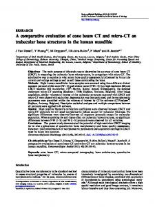
System description A simplified block diagram of the processor is shown in Fig. 1. This diagram and the following description are a summary of information which was supplied by the manufacturer (Micro Consultants Ltd, 1982). Video signals from a fluoroscopic system or other source are amplified at the input to the processor. The transformation can be linear or logarithmic. The amplifier's output is digitized to 8 bits using an analogue-to-digital Correspondence to: K. P. Maher, Medical Radiations Group, Department of Applied Physics, Royal Melbourne Institute of Technology, GPO Box 2476V, Melbourne 3001, Australia. 62
converter (ADC) which samples data at 10 MHz. Digitized images are stored in a 0.25 MByte semiconductor memory in real time. This memory is configured for storage of images at 512x512x8 bit or 256 x 256 x 8 bit resolution. Real-time processing is achieved using a recursive video processor (RVP). This circuitry arithmetically operates on incoming images from the ADC (or from disk) and stored images from semiconductor memory on a pixel-by-pixel basis. Operations include image subtraction, integration and temporal filtration. The temporal filtration algorithm is given by: />n(x,y) = */B(x, (1) where Pn(\,y) represents an image stored in memory during video frame n; /n(x,y), an incoming image from the ADC during this frame period and k, a weighting factor which is positive and less than one. This weighting factor is equal to the reciprocal of the number of video frames, N, which define the time constant of the temporal filter. Processed images can be contrast enhanced using an 8-bit look-up-table (LUT) before conversion from digital to analogue form and display. Images in semiconductor memory can also be transferred to two 84 MByte Winchester disks (Fujitzu, M2312K) for subsequent retrieval. Transfer rates are 3.57 frames per s for 512x512 resolution and 12.5 frames per s for 256 x 256 resolution. Images in semiconductor memory can also be transferred to a microcomputer (Digital Equipment Corp. LSI 11/23) for analysis or additional processing. The processor is controlled by registers which are distributed throughout the circuitry. These registers can be loaded with instructions generated by the microcomputer. The system is programmed in Fortran and has a library of subroutines which control the flow of image data. The British Journal of Radiology, January 1988
Processing functions of a DSA image processor
L 8 Bit ADC
RVP
0 25 MB. MEMORY
LUT
—©o/p
LIN/LOG AMP
Figure 1. Block diagram of the DSA image processor.
Technical evaluation Images for evaluation were obtained by connecting the image processor to a conventional fluoroscopic system fitted with an under-couch tube (Shimadzu XHD150B generator/Precise Optics PI200 image intensifier and plumbicon video camera). Automatic exposure and gain facilities of the fluoroscopic system were disabled and continuous radiation exposures generated. The transfer characteristics of the fluoroscopic system and image processor were assessed using an ionization chamber (MDH, 2025) which was placed roughly 10 cm above the fluoroscopic table. The mean pixel value in a region covering the central portion of the chamber was obtained for each acquired image. The functions of image integration and temporal filtration of the image processor were evaluated using densitometric analysis of individual pixels in images of a uniform aluminium block, before and after processing. On the basis of these analyses, Fortran programs were written which performed similar functions using real arithmetic. The resultant images were compared densitometrically to those conventionally processed by the system. Noise in images was estimated by first subtracting two images using a software technique. Subtraction was necessary so that effects from image non-uniformities could be removed (Malone et al, 1985). The standard deviation of pixel values was then computed and divided by 2*. Signal-to-noise ratio was obtained by relating the estimated noise to the mean pixel value in the central area of either image used for subtraction. Care was taken to ensure statistical independence of all images used for noise analysis. In particular, for evaluation of the temporal filtration function, the images analysed were acquired after running the filter for a period greater than 10 times its time constant. Images of the aluminium block were used as mask Vol. 61, No. 721
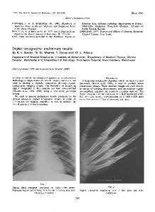
images for evaluation of the subtraction function. The second image used for subtraction was obtained by placing a uniform Perspex plate on top of the aluminium block. The mask image was subtracted from this second image. Densitometric analysis and software simulation, as outlined above, were then performed. Clinical studies Digital subtraction angiography images were produced using the fluoroscopic system described above. For intravenous studies, a 6.5 F pigtail catheter was normally advanced to the superior or inferior vena cava and 40 cm 3 of Hexabrix 320 (sodium and meglumine ioxaglate) (May & Baker) was injected using an angiographic injector (Medrad, Mark IV). For intraarterial studies, 5-10 cm 3 of contrast medium was injected by hand. Nominal continuous exposures of 60-75 kVp, 1-3 mA were employed in all procedures. The original image sequences were recorded using a video cassette recorder (Sony, VO5630) and subsequently replayed into the image processor. Images were digitized at 512 x 512 x 8 bit resolution and a temporal filter with k = 0.25 (Equation 1) was normally applied, prior to image subtraction and contrast enhancement. Results Transfer characteristics The transfer characteristics of the system are shown in Fig. 2. For linear transformation, it is seen that a straight line (r = 0.9999) was obtained. The intercept with the vertical axis corresponds to a d.c. voltage of roughly 130 mV on the video signal from the plumbicon camera. When the data are corrected for this effect, the linearity of the total system is given by y = 0.989. It is also seen in Fig. 2 that logarithmic transformation of images generated a log-like curve. However, it is 63
K. P. Maker, J. F. Malone, G. D. Hurley and D. P. Mclnerney
200
x °-100
100
200 300 400 EXPOSURE (nC k g V 1 )
Figure 2. Transfer characteristics of the imaging system for linear transformation (A) and for logarithmic transformation (B).
apparent that the response does not fully exploit the grey scale of the processor. Image integration Examination of the hardware-based image integration function showed that it operates on 256 x 256 matrices for a maximum of 128 integrations. However, the function was found not to be a true integration. In fact, it is equivalent to summing pixel values in successive images and then shifting results so that the eight most significant bits of data are finally stored in memory. It was also found that results were identical to averaging image data using integer-based arithmetic. Improvements obtained in the signal-to-noise ratio (SNR) of images are shown in Fig. 3, where SNR improvement is defined as the SNR of a processed image divided by the SNR of an unprocessed image. Signal-to-noise ratio improvements of N*, where N is the number of frames integrated, are also shown for comparison purposes. This behaviour would be expected in a true integration or averaging process. Temporal filtration Analysis of images processed by temporal filtration indicated that the algorithm used can be given by (refer to Equation 1): Pn(x,y) = *[/ n (x,y)- J P n _ 1 (x,y)]-r-P n - 1 (x,y) 64
(2)
2
4
8
16
32
64
128
NUMBER OF FRAMES.N Figure 3. Observed (A) and theoretically expected (B) improvements in image SNR for image integration.
for 256x256 matrices or 512x512 matrices. It was found that this function was equivalent to subtracting a stored image from an incoming image, shifting the result using integer-based arithmetic and summing with the stored image. Improvements obtained in the signalto-noise ratio of images are shown in Fig. 4, along with theoretically expected improvements of (2iV—1)* (Riederer et al, 1983). Image subtraction Examination of the hardware-based subtraction function indicated that it operates on 256 x 256 matrices or 512x512 matrices by subtracting an image stored in semiconductor memory from an incoming image and shifting results up by seven bits. Thus null results are stored with a pixel value of 128 i.e. mid-grey on the grey scale). Negative results are stored as darker grey levels and positive results as brighter grey levels. It was also found that pixel values in subtracted images were roughly 50% less than those obtained from software-based subtraction (Fig. 5). Closer inspection of these data revealed that this halving process is achieved in a manner similar to shifting subtraction results down by 1 bit. It was found that the effect is similar to using integer-based arithmetic for divisions by two in a software program. Clinical studies The application of the processor to digital subtraction angiography is illustrated by the images in Figs 6 The British Journal of Radiology, January 1988
Processing functions of a DSA image processor
Finally it can be noticed from Figs 6 and 7 that portions of the top and bottom of the circular field of view of thefluoroscopicsystem are missing. This loss of data in the image processor may be attributed to a requirement for accommodation of a 625-line video image in a 512x512 matrix. It was determined that 32 lines at both the top and the bottom of an analogue image were discarded prior to semiconductor storage. These lines were output as black by the processor, as a result. In addition, it was found that image digitization at 256 x 256 resolution resulted in a further loss of image data. This occurred because the ADC is designed to sample continuously at a constant rate. Consequently, storage at this resolution is achieved by discarding every second digitized pixel in a single video field. Discussion
8 16 32 64 128 NUMBER OF FRAMES.N Figure 4. Observed (A) and theoretically expected (B) improvements in image SNR for temporal filtration.
and 7. These images are typical of those obtained routinely with the system. Over 250 patients have been studied. The majority of the studies were performed on outpatients for the evaluation of carotid artery, aortic, renal, parathyroid and peripheral vascular disease. The greatest number of examinations was performed on patients with severe peripheral vascular disease (Mclnerney et al, 1986).