Evaluation of Traffic Speed Continuous Deflection Devices Gerardo W. Flintsch (Corresponding Author) Director, Center for Sustainable Transportation Infrastructure, Virginia Tech Transportation Institute Professor, The Charles Via, Jr. Department of Civil and Environmental Engineering 3500 Transportation Research Plaza Virginia Tech, Blacksburg, VA 24061-0105 Phone: (540) 231-9748, Fax: (540) 231-1555, Email:
[email protected]
Brian Ferne Transport Research Laboratory, Crowthorne House, Nine Mile Ride, Wokingham, Berkshire, RG40 3GA, United Kingdom Phone: +44 (0)1344 77 0668, Fax: +44 (0)1344 77 0356, Email:
[email protected]
Brian Diefenderfer Virginia Center for Transportation Innovation and Research 530 Edgemont Road, Charlottesville, VA 22903 Phone: (434) 293-1944, Fax: (434) 293-1990, Email:
[email protected]
Samer Katicha Senior Research Associate, Center for Sustainable Transportation Infrastructure, Virginia Tech Transportation Institute 3500 Transportation Research Plaza, Blacksburg, VA 24061 Phone: (540) 231-1586, Fax: (540) 231-1555, Email:
[email protected]
James Bryce Graduate Research Assistant, Virginia Tech Transportation Institute Department of Civil and Environmental Engineering, Virginia Tech 3500 Transportation Research Plaza, Blacksburg, VA 24061 Phone: (573) 289-9236, Fax: (540) 231-1555, Email:
[email protected]
Simon Nell Transportation Research Laboratory, Crowthorne House, Nine Mile Ride, Wokingham, Berkshire, RG40 3GA, United Kingdom Phone: +44 (0)1344 77 0236, Fax: +44 (0)1344 77 0356, Email:
[email protected]
Submitted August 1, 2011 Word Count Abstract: 123 Text: 4,499 Figures: 6x250 = 1,500 Tables: 4x250 = 1,000 ---------------------------Total: 7,122
TRB 2012 Annual Meeting
Paper revised from original submittal.
Flintsch, Ferne, Diefenderfer, Katicha, Bryce, and Nell
2
ABSTRACT Continuous deflection measuring devices, also called continuous deflectometers, are increasingly being used to support project-level and network-level pavement management decisions. Continuous deflectometers are non-destructive pavement evaluation devices that measure pavement deflections caused by a moving load. Some continuous deflectometers can perform measurements with little to no traffic control, which makes them more advantageous to use than stationary devices such as the falling weight deflectometer. This paper discusses the current technologies implemented in different types of deflectometers and identifies the most promising devices for use to support network-level pavement management decisions. In that respect, two devices (the Rolling Wheel Deflectometer and the Traffic Speed Deflectometer) have shown promising results and are being further evaluated under the Second Strategic Highway Research Program, Project R06 (F).
TRB 2012 Annual Meeting
Paper revised from original submittal.
Flintsch, Ferne, Diefenderfer, Katicha, Bryce, and Nell
3
INTRODUCTION Deflections provide valuable information about the in situ structural parameters of pavements. Currently, deflection measurements are most often obtained using the falling weight deflectometer (FWD), a device that requires traffic control and measures deflections while stationary at discrete locations along the pavement structure. The FWD has proven to be an important tool in the non-destructive evaluation of existing pavements, and many state and local pavement management systems (PMSs) utilize the measurements from the FWD. However, recent technological advancements have resulted in the development of continuous deflection measuring devices, also called continuous deflectometers, that can provide better spatial coverage than static devices such as the FWD while requiring little to no traffic management. OBJECTIVE Many states are beginning to implement deflection testing into their network-level pavement management program as reported in the National Cooperative Highway Research Program (NCHRP) Synthesis of Highway Practice 39-01(1). Although continuous deflectometers do not currently provide detailed information that can be obtained using the FWD (such as the deflection bowl), they have the benefit of being able to efficiently measure pavement response from an applied load for network-level purposes. This paper evaluates currently available continuous deflectometers that are capable of being used as part of a PMS. METHODOLOGY This paper begins by identifying candidate continuous deflectometers that show the greatest potential to meet project and user requirements. The information about the continuous deflectometers and user requirements was obtained by conducting an extensive literature review and by surveys of state highway officials, as will be discussed in this paper. Continuous deflectometers were then categorized by their potential to meet the user and project needs that were found during the literature review and survey. Using available data and information from communications with the manufacturers, continuous deflectometers were evaluated based on their measurement capability and suitability for implementation into network- and project-level analyses. Definition of Devices to be Considered For this research, a continuous deflectometer is defined as a constantly moving deflection measuring device that can collect data at intervals of approximately 300 mm (1 ft) or less using load levels typical of truck loading (i.e., 40 to 50 kN [9 to 11 kips] per wheel or load assembly). Continuous deflectometers should be able to measure pavement bearing capacity without the need for the vehicle or the measuring device to remain stationary. The ideal case would be for the continuous deflectometer to operate at normal traffic speed and to require no traffic management. It should be noted that the interval of data collection in the definition above is not necessarily the interval at which measurements are reported. The interval at which measurements are reported will often be much greater than the interval of data collection in order to filter out the noise in the signal.
TRB 2012 Annual Meeting
Paper revised from original submittal.
Flintsch, Ferne, Diefenderfer, Katicha, Bryce, and Nell
4
Reference Device Given that most deflection testing is currently performed using the FWD, this research uses the FWD as a reference device for determining the accuracy of continuous deflectometer measurements. However, it should be noted that this might not be considered a “true” reference given the differences in the response of pavements under a loaded wheel traveling at traffic speed and the response created by the FWD. An FWD test production rate of approximately 4 lane-km (2.5 lane-mi) per day is typical, assuming testing at a 23 m (75 ft) interval (2). This testing scheme is best suited for project-level testing, but agencies that employ FWD for network-level testing may adjust this test spacing to achieve a production rate of approximately 32 to 40 lane-km (20 to 25 lane-mi) per day, assuming a 320 m (0.2 mi) interval (2). Determination of User Needs The demand and potential value of continuous deflectometers for use in pavement rehabilitation strategies were evaluated through a survey of state and provincial Departments of Transportation (DOTs). The survey focused on assessing technical needs and determining the value that DOTs place on the information that can be obtained with the use of continuous deflectometers. The survey was divided into two stages. The first stage comprised a web survey, and the second stage comprised phone interviews with nine states that have experience using continuous deflectometers. The phone interviews were conducted with the following nine state DOTs: Arizona (AZ), Florida (FL), Indiana (IN), Kansas (KS), Montana (MT), New Hampshire (NH), New Mexico (NM), Oregon (OR), and Virginia (VA). The web survey was sent to 56 potential participants, of which 44 completed the survey (79 percent response rate). Thirty-seven of the survey respondents (84 percent) replied that their agencies use pavement deflection testing mainly at the project level, although some respondents indicated use at the network level. All respondents that perform pavement deflection testing use the FWD. Table 1 summarizes the main engineering parameters that the survey respondents would like to derive from the deflection measurements. TABLE 1 Summary of Response to the Question: “What are the Key Engineering Parameters That You Would Wish to Derive from Deflection Testing?”
1 2
Broken Down by Pavement Type
Number of Respondents
%
Subgrade structural capacity
31
86%
31
16
14
6
Deflection values
26
72%
26
14
12
5
Layer moduli
25
69%
25
12
8
3
Joint/Crack Transfer Efficiency
19
53%
2
8
19
4
In-service structural number
18
50%
18
10
6
2
Deflection basin area
18
50%
17
7
7
1
Pavement remaining service life
14
39%
14
10
8
4
Depth to bedrock
6
17%
6
3
2
1
Key Engineering Parameters
Flexible Composite JCP1
CRCP2
JCP = Jointed concrete pavements CRCP = Continuously reinforced concrete pavements
TRB 2012 Annual Meeting
Paper revised from original submittal.
Flintsch, Ferne, Diefenderfer, Katicha, Bryce, and Nell
5
Perhaps the primary benefit of a continuous deflection measuring device is its ability to provide an overall assessment of the structural condition of the pavement network. Deflection test results can be incorporated into an agency’s PMS to support maintenance and rehabilitation strategy scoping and resource allocation decisions, among other asset management business functions. Although most of the respondent agencies (93 percent) have implemented a PMS, only five of those agencies incorporate the results of deflection testing into their PMS. The obtained responses indicate that most respondents envision using a continuous deflection device for network-level data collection. Within this framework, speed is perceived as a critical characteristic even if it means sacrificing some accuracy. It is important that the results obtained from deflection testing using a continuous deflection measuring device are comparable to static deflection measurements such as those obtained using an FWD. The primary applications of the continuous deflection device at the network level would be to: 1. Help identify “weak” (or structurally deficient) areas that can then be investigated further at the project level, 2. Provide network-level data to calculate a structural health index that can be incorporated into a PMS, and 3. Differentiate sections that may be ideal candidates for preservation (quality structural capacity) from those that would likely require a heavier treatment (showing structural deficiencies). Additionally, some states indicated that they currently use deflection values from FWDs in their PMSs. The parameters that have been used by DOTs that currently use FWD data in a PMS include: the effective structural number and layer moduli for flexible pavements and the area and k-value for rigid pavements. A number of interviewed state DOTs (IN, KS, NH, OR, and VA) have had some experience using continuous deflectometers, mostly through Federal Highway Administration (FHWA)-sponsored demonstration projects. In general, the deflection tests were found to be repeatable, successful in identifying problem areas, and generally correlated with FWD test results (although some trials did not show an ideal correlation as discussed in subsequent sections). Potential Candidate Devices A set of deflectometer devices to be considered was developed based on the literature review and interviews with DOT professionals. These devices were reviewed thoroughly and evaluated based on their measurement capabilities and their ability to meet user needs. Table 2 presents the devices that the research team has identified as potentially promising continuous deflectometers. The research team identified two devices as the most promising to deliver the information needed by the users under operating conditions compatible with the research objectives. These devices are the Rolling Wheel Deflectometer (RWD) and the Traffic Speed Deflectometer (TSD). Devices in which the vehicle is non-stationary while testing but the actual measurement equipment is stationary while sampling (e.g., Deflectograph) were not considered because they did not conform to the adopted definition of a continuous deflection device. The Portancemetre and the Measuring Ball were also eliminated from consideration because they do not apply loads similar to that of a heavy vehicle. Since the magnitude of the load is small and the speed slow, these devices are primarily used for quality checks on unpaved surfaces.
TRB 2012 Annual Meeting
Paper revised from original submittal.
Flintsch, Ferne, Diefenderfer, Katicha, Bryce, and Nell
6
The Road Deflection Tester (RDT) and Airfield Rolling Weight Deflectometer (ARWD) were also eliminated from further consideration because the existing prototypes have been decommissioned or reassigned to other uses. The Rolling Dynamic Deflectometer (RDD) was also originally identified as an ideal candidate, especially for measuring on concrete pavements. However, the RDD was not selected for further evaluation because the user needs survey indicated that the majority of the users would prefer a device that can measure at traffic speed (e.g., at least 55 km/h [35 mph]). The original RDD operated at approximately 1.5 km/h (1 mph), but it has recently been updated to operate at 5 km/h (3 mph).
TABLE 2 Devices Considered by the Second Strategic Highway Research Program (3) Device
Loading Mechanism
Load Magnitude
Measurement
Device Speed
Portancemetre
Eccentric Vibrating Mass (35 Hz)
10 kN (2.2 kips) Static 6 kN (1.3 kips) Dynamic
Vertical Acceleration from Load
3 to 4 km/h (2 to 2.5 mph)
Measuring Ball
Vibrating Wheel
Unknown
Vertical Acceleration from Load
Moving FWD
N/A, Decommissioned prototype
Traffic Speed Deflectometer (TSD) Rolling Dynamic Deflectometer (RDD)
Sample Interval 30 mm (1.2 in.) reported at 1 m (3.3 ft)
Status
5 km/h (3 mph)
Unknown
Unknown
30 km/h (19 mph)
15 m (50 ft)
Decommissioned Prototype
Dual Tires
50 kN (11 kips)
Doppler Laser (Pavement Deflection Velocity)
70 km/h (45 mph)
20 mm (0.8 in.)
Production Model
ServoHydraulic Vibrator through Dual Tires
65 kN to 180 kN (15 kips to 40 kips) Static 310 kN (70 kips) Dynamic
Vertical Acceleration from Load
5 km/h (3 mph)
Unknown
Working Prototype
40 kN (9 kip)
Laser Distance Measurement System
80 km/h (50 mph)
11 mm (0.5 in.)
Working Prototype
35 km/h (20 mph)
Unknown
Decommissioned Prototype
20 mm (0.8 in.)
Prototype Reassigned to Other Uses
Rolling Wheel Deflectometer (RWD)
Dual Tires
Airfield Rolling Weight Deflectometer (ARWD)
Single Wheel
40 kN (9 kip)
Laser Distance Measurement System
Road Deflection Tester (RDT)
Dual Tires
40 kN to 70 kN (9 kips to 15.7 kips)
Laser Distance Measurement System
70 km/h (45 mph)
Image-Based Deflection Measuring Device
N/A, Only a laboratory version is available
Image Pattern Detection
Expected: 4 km/h (2.5 mph)
TRB 2012 Annual Meeting
Production Model
Laboratory Prototype
Paper revised from original submittal.
Flintsch, Ferne, Diefenderfer, Katicha, Bryce, and Nell
7
RWD The RWD utilizes a “spatially coincident” methodology for measuring pavement deflection. This method was originally developed by the Transport and Road Research Laboratory (TRRL) and was furthered by Dr. Milton Harr at Purdue University. Three lasers are used in the RWD to measure the distance to the unloaded pavement surface (i.e., forward of and outside the deflection basin), and a fourth laser located between the dual tires and just behind the rear axle measures the distance to the deflected pavement surface. The deflection is calculated by comparing the laser scan profile as the RWD moves forward. The beam uses a curved extension to pass under and between the dual tires, thereby placing the rearmost laser approximately 150 mm (6 in.) rear of the axle centerline and 178 mm (7 in.) above the roadway surface. The wheels are spaced a safe distance from the laser and beam using custom lugs spacers (4). The RWD 2 kHz lasers take readings approximately every 11 mm (0.5 in.) at 89 km/h (55 mph), resulting in extremely large data sets. The average deflection every 160 m (0.1 mi) is typically reported, which helps reduce scatter and file size. The data are generally filtered prior to the analysis to eliminate outliers due to bridges, sudden changes in speed, etc. Additional details about the RWD measurement process are presented elsewhere (5, 6). The RWD technology can test approximately 320 to 480 km (200 to 300 lane-mi) per day. A potential benefit of the RWD is that the load, loading mechanism, and loading rate of the RWD are thought to more closely match the actual dynamic effects on pavements caused by vehicle loading. In its current state of development, it is anticipated that the RWD could be used to pre-screen the pavement network to identify areas that might require more detailed study at the project level using traditional techniques (such as those employed by the FWD) and/or to identify segments that could be ideal candidates for pavement preservation. The FHWA has sponsored RWD demonstration projects throughout the United States. Testing has been conducted in coordination with at least 16 U.S. state highway agencies. One of the earliest RWD test reports was authored by Arora describing testing in Texas in 2004 (7). The RWD was used to test approximately 425 km (264 lane-mi); a variety of state routes with five repeat runs per roadway) with some companion FWD testing. FWD values ranged from approximately 100 to 1,300 microns (4 to 50 mils [10-3 in]). The authors stated that the RWD testing was repeatable based on visual observation of the plotted deflection results. In discussing a relationship between RWD and FWD results, the authors stated that some relationship exists although the data “shows some scatter especially at smaller deflection values.” The authors suggested that lower deflection values might be measurable only at lower speeds. Gedafa reported in 2006 on RWD testing performed in Kansas using 333 km (207 mi) of non-interstate highway (8). The results of the RWD testing were compared to FWD testing conducted from 1998 to 2006. RWD testing was performed at 89 km/h (55 mph) with deflection readings averaged every 160 m (0.1 mi). The FWD data were collected at five to 10 points per mile. The average FWD center deflection value ranged from approximately 0.13 to 0.45 mm (5 to 18 mils) for a 40 kN (9 kips) load. The results showed that the RWD reading and the FWD center deflection value were statistically similar based on a significant difference test statistic. A linear regression analysis was also performed that showed a strong correlation between FWD and RWD readings. Virginia reported RWD testing in 2005 using portions of two interstate routes and a loop comprising primary rural highways (2). All RWD testing was conducted at or near the
TRB 2012 Annual Meeting
Paper revised from original submittal.
Flintsch, Ferne, Diefenderfer, Katicha, Bryce, and Nell
8
prevailing traffic speed. Companion FWD testing was conducted in 2006 on the two interstate test sections. The FWD values ranged from 0.08 to 0.38 mm (3 to 15 mils) with a majority less than 0.2 mm (8 mils; using a 40 kN [9 kips] load). The two interstate test sections comprised hot mix asphalt (HMA; 200 to 300 mm [8 to 12 in.]) over compacted aggregate and HMA (100 to 150 mm [4 to 6 in.]) over continuously reinforced concrete pavement (CRCP; 200 mm [8 in.]). Statistical testing of RWD repeatability was performed by use of a non-paired t-test assuming equal variances. The results showed that for eight of 15 trials conducted on interstate highways and all non-interstate test sections, the RWD data were repeatable. An inadequate linear correlation was found between the RWD and FWD measurements (adjusted R2 values less than 0.2). However, the FWD measurements were taken several months after the RWD measurements and only on the interstate sections that had relatively low and uniform deflections. The results also suggested that the deflection value may be influenced by surface texture as the standard deviation varied approximately at locations where the HMA surface mixture also varied. TSD The TSD measures the pavement deflection velocity using a set of velocity-sensing lasers based on the Doppler principle. The lasers are mounted at a small angle to measure the horizontal vehicle velocity, the vertical and horizontal vehicle suspension velocity, and the vertical pavement deflection velocity. To remove the measurement dependence on vehicle speed, the deflection velocity is divided by the instantaneous survey speed to provide a measurement of deflection slope. Deflection velocity is measured in mm/s while survey speed is measured in m/s; therefore, deflection slope measurements are output in units of mm/m (9). The first two prototypes of the TSD were developed by the manufacturer Greenwood Engineering A/S of Denmark, and two updated versions have recently been built. Of the earlier prototypes, one is owned and operated by the Danish Road Institute (DRI), and the other is owned by the UK Highways Agency (HA) and is operated on behalf of the UK HA by the UK Transport Research Laboratory (TRL). The DRI and Greenwood Engineering A/S jointly developed the TSD, initially called the High Speed Deflectograph (HSD), and have published a number of papers about this work (10). An early independent evaluation conducted by the Laboratoire Central des Ponts et Chaussees (LCPC) in 2003 showed that, even though the early prototype had limitations, it demonstrated ideal repeatability in the short term and a quality degree of correlation with the maximum deflection recorded by other devices such as the FWD and the Deflectograph (11). The DRI tested its main network each year from 2005 to 2007. Based on this experience, Baltzer reported a DRI daily survey coverage for the machine of approximately 170 to 225 km (105 to 140 mi) (12). The TRL has reported its development and performance in a recent conference paper (13). Measurement Capabilities of Selected Devices The current RWD is designed to measure only the vertical deflection under the nearside wheel assembly. At present the machine does not have the capability to measure the full deflection basin or a sampled representation of it as provided by the multiple sensors fitted to most FWDs. However, recent modifications have included an additional sensor to the RWD at a position further away from the rear axle to provide more deflection information. The two existing versions of the TSD measure the vertical velocity of the pavement response to the nearside dual
TRB 2012 Annual Meeting
Paper revised from original submittal.
Flintsch, Ferne, Diefenderfer, Katicha, Bryce, and Nell
9
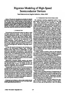
wheel assembly loading at three locations in front of the rear axle, which is then converted to deflection slope. The sensors measure deflection velocity, not displacement, so the measurements cannot directly provide either the full deflection basin or the maximum deflection value. However, the measured slopes closest to the axle (i.e., P100 and P300) have shown a strong relationship to the peak deflections measured by other devices. The TSD manufacturer, Greenwood Engineering A/S, has also developed an approximate relationship that can be fitted to the three offset slope measurements, thus enabling the estimation of the peak deflection and surface curvature index of the pavement surface under load. It is not currently possible to estimate the full deflection bowl from the sensor configurations, but machines with more sensors have recently been constructed (in one case with six measurement sensors and one reference sensor). The additional sensors should enable such information as the full deflection bowl to be calculated. Accuracy Accuracy of the selected devices depends on many factors. Thus, accuracy will be considered under a number of subheadings: choice of averaging length, short-term repeatability, effect of external variables, and comparison with other deflection measures. For each of the subheadings the capability of each of the two devices is considered based on the available information collected within this study. The effect of external variables will not be discussed in this paper. Choice of Averaging Length An RWD demonstration conducted at the Eastern Federal Lands Highway Division (EFLHD) included a comparison using 160 m and 32 m (0.1 and 0.02 mi) intervals to average the results from the testing. The data show that decreasing the sample unit length does not significantly affect the overall trend of the deflection profile (or the mean deflection for the overall section), but it does increase variability over the section length. Based on these limited results, the manufacturer has cautioned against using a sampling interval that is too small to sufficiently reduce random error (14). The TSD collects raw data at approximately 1,000 Hz, but there is significant random noise in this raw signal. Even when averaged across a 0.1m (4 in.) length, this noise is noticeable as illustrated in FIGURE 1. Also shown in this figure are 1 m (40 in.), 10 m (33 ft) and 100 m (1/16 mi) continuous averages. The site shown in Figure 1 is generally of a variable and weak composite construction with correspondingly variable deflections. The figure shows how the true deflection profile is probably suppressed as the averaging length increases from 1 m to 10 m (3.3 ft to 33 ft). Therefore in the UK it has been decided to store results at 1 m (3 ft) intervals and generally report results as 10 m (33 ft) averages. From stations 215 to 250 m (705 to 820 ft) in FIGURE 1, the construction changes to a rigid concrete construction that has a relatively low and uniform deflection response. This exaggerated scale of deflections suggests that on the weak composite construction even the 10 m average length hides some true deflection variations. This is discussed further in the following repeatability section.
TRB 2012 Annual Meeting
Paper revised from original submittal.
Flintsch, Ferne, Diefenderfer, Katicha, Bryce, and Nell
10
Slope Vs. Chainage, TRL Large Loop (Long Straight) 23-Jun-09, P100 2.5
Deflection Slope [mm/m]
2
1.5
1
0.5
0 0
50
100
150
200
250
300
Chainage [m] 0.1m
1m
10m
100m
FIGURE 1 TSD deflection slope profile for TRL track with various averaging lengths.
Short-term Repeatability Several of the RWD demonstration projects included multiple runs. In general, the various evaluations show relatively ideal repeatability that seems to be appropriate for network-level analysis. However, Diefenderfer conducted statistical testing of RWD repeatability by use of a non-paired t-test assuming equal variances, and the results showed that for only eight of 15 trials the RWD data were repeatable (2). Of the non-interstate test sections, 100 percent of the trials were found to be repeatable. This raised some questions about the applicability of the system for detailed (e.g., project-level) evaluations. FIGURE 2 shows an example of three repeated runs conducted on a stretch of interstate highway in VA. The repeatability standard deviation for the average 0.1 mi segments is shown at the bottom of the chart; the average standard deviation was 20 microns (0.79 mils) or 17 percent of the mean deflection. However, the repeatability standard deviation of the average values for the entire tested sections showed ideal repeatability (Table 3).
TRB 2012 Annual Meeting
Paper revised from original submittal.
Flintsch, Ferne, Diefenderfer, Katicha, Bryce, and Nell
11
Eastbound I-64- Exit 107, Crozet to Exit 136, Palmyra 10
8
Deflection (mils)
Pass 1 (P1) Pass 2 (P2) Pass 3 (P3) Std Deviation (0.1 mi)
Correlation Matrix P1 P2 P3 P1 1.00 0.69 0.63 P2 0.69 1.00 0.65 P3 0.63 0.65 1.00
6
4
2
0 105
110
115
120
125
130
135
140
Mile Marker FIGURE 2 Repeated runs of the RWD on I-64 in Virginia (2). TABLE 3 Summary Statistics for Average Section RWD Deflections of I-64 and I-81 (2). Highway
Average (mils)
Repeatability Std. dev. (mils)
Average (microns)
Repeatability Std. dev. (microns)
I-64 - Eastbound
4.53
0.28
115.1
7.3
I-64 - Westbound
4.7
0.26
119.4
6.6
I-81 - Northbound
7.77
0.14
197.4
3.5
I-81 - Southbound
5.08
0.59
129.0
15.0
For the UK HA TSD, Ferne reported the results of an analysis conducted to investigate the effect of testing speed (9). Measurements were taken on the TRL track across a range of speeds, and the results showed that a slightly lower value of deflection slope was recorded as the speed was increased. This being the case, the device speeds used during additional tests were strictly controlled to enable repeatable results to be obtained. FIGURE 3 shows a sample of the results of six runs conducted at a nominal speed of 70 km/h (45 mph) on a 440 m (0.25 mi) length of the TRL track, which comprises mainly a composite pavement and a 50 m (165 ft) length of jointed concrete. The data showed reasonable short-term repeatability expressed across 10 m lengths, with a relatively low standard deviation despite the range of deflection slopes measured (i.e., changing by a factor of more than seven).
TRB 2012 Annual Meeting
Paper revised from original submittal.
Flintsch, Ferne, Diefenderfer, Katicha, Bryce, and Nell
12
1.75
1.5
Std Deviation (10m)
Slope [mm/m]
1.25
1
0.75
0.5
0.25
0 0
50
100
150
200
250
300
350
400
450
Chainage [m]
FIGURE 3 Repeatability of deflection slope at 70 km/h (45 mph) on the TRL track (9). The repeatability of the latest version of the UK HA TSD has been assessed on a small number of UK roads. The results of these tests in terms of the standard deviation of the mean values of each of five runs of various lengths have been summarized in Table 4 for the P100 and P300 TSD sensors. In order to make comparisons to the U.S. RWD machine, the results in terms of TSD slope have been converted into approximately equivalent peak FWD measurements at a load level of 40 kN (9 kips) as provided in Table 4. The conversion was achieved by using an average relationship where a change in slope of 0.15 mm/m is taken to be roughly equivalent to a change in peak FWD deflection under a 40 kN (9 kip) load of 80 microns (3 mils). TABLE 4 Repeatability Standard Deviation of TSD for Five Runs in Terms of TSD Slope Converted to Equivalent FWD Measurement at 40 kN (9 kip) Load for Short-term Repeatability Site
Overall Length (m/mi)
Averaging length
Sensor 10 m (33 ft)
100 m (330 ft)
160.9 m (0.1 mi)
UK Site 1
291 m/ 0.2 mi
P100
38 µm/1.5 mil
25 µm/1.0 mil
21 µm/0.8 mil
P300
28 µm/1.1 mil
20 µm/0.8 mil
18 µm/0.7 mil
UK Site A
1080 m/ 0.7 mi
P100
20 µm/0.8 mil
6 µm/0.2 mil
5 µm/0.2 mil
P300
20 µm/0.8 mil
7 µm/0.3 mil
6 µm/0.2 mil
UK Site B
3871 m/ 2.4 mi
P100
29 µm/1.1 mil
13 µm/0.5 mil
12 µm/0.5 mil
P300
38 µm/1.5 mil
28 µm/1.1 mil
27 µm/1.1 mil
TRB 2012 Annual Meeting
Paper revised from original submittal.
Flintsch, Ferne, Diefenderfer, Katicha, Bryce, and Nell
13
The ideal level of short-term repeatability of the TSD that is achievable under controlled conditions can also be observed graphically. FIGURE 4 shows a 20 m (66 ft) sample length of the TRL track with the TSD P100 sensor results calculated at 1 m (3 ft) intervals plotted against distance for all five repeat runs. The repeated identification of weak spots at the same location (e.g., stations 182 to 184 m [613 to 617 ft] and 191 to 193 m [146 to 650 ft]) is clearly seen.
Slope Vs. Chainage, UK_F1 (TRL-C), P100 (1m data) 3.0
Deflection Slope [mm/m]
2.5
2.0
1.5
1.0
0.5
0.0 180
182
184
186
188
190
192
194
196
198
200
Chainage [m]
FIGURE 4 Selected 20 m (66 ft) length of TSD slope data as 1 m (3.3 ft) means on TRL track. Comparison with Other Deflection Measures Several of the RWD demonstrations included FWD measurements on some of the same pavement sections. However, not all of the FWD tests were conducted at the same time that the RWD measurements were taken. FIGURE 5 shows examples of section-level comparisons between RWD and FWD maximum deflections. The RWD reports collected during the followup interviews suggest that the average results of the RWD measurements normalized to a standard temperature correlate relatively well with the average maximum FWD deflection when aggregated by homogenous sections.
TRB 2012 Annual Meeting
Paper revised from original submittal.
14
RWD Deflection (mils)
Flintsch, Ferne, Diefenderfer, Katicha, Bryce, and Nell
FWD Deflection (mils)
RWD Deflection (mils)
(a) Kansas
FWD Deflection (mils) (c) Iowa FIGURE 5 Examples of RWD vs. FWD comparisons (15). Many comparisons have been made between the TSD and other deflection measuring devices. An early independent evaluation (2003) by the LCPC of the first DRI prototype showed a strong correlation between the slope measured by the DRI TSD and the peak central deflection measured by an FWD across a range of sites in France (11). Comparisons in the UK between the HA TSD and FWD measurements have been less applicable because such evaluations utilize the common UK deflection measuring device, the Deflectograph. Figure 6 shows a comparison between an FWD central deflection profile at 2 m (6.6 ft) intervals compared with a TSD deflection slope profile averaged across the same
TRB 2012 Annual Meeting
Paper revised from original submittal.
Flintsch, Ferne, Diefenderfer, Katicha, Bryce, and Nell
15
intervals on a 400 m (1,300 ft) section of the TRL track. The pavement structure includes both weak flexible composite materials and rigid concrete. The similarities in the shape of the two profiles are very encouraging despite the four-year interval between the tests. It should be noted that the vertical scales of the two parameters are relatively arbitrary and have been adjusted to approximately align the two profiles vertically. TRL Track Long Straight. FWD 2m spacings (17-Oct-2005), TSD P100 2m averaging (23-Jun-2009) 1000
2.5
900 800
2.0
600
1.5
500 400
1.0
TSD Deflection Slope [mm/m]
FWD Deflection [μm]
700
300 200
0.5
100 0
0.0
0
50
100
150
200
250
300
350
400
Chainage [m] FWD D1
TSD P100
FIGURE 6 Comparison of HA TSD slope and FWD central deflection profiles on flexible composite pavement. Operating Conditions When operating at a normal survey speed neither of the candidate devices requires traffic management, though at slower speeds some form of traffic management will be necessary. Research has shown that new binder-rich surfaces can cause faulty operation of the velocity sensors on the TSD. However, normal measuring performance returns after a few months of trafficking, and the surfacing becomes less reflective. Otherwise, the equipment functions reliably on a range of surfaces. Both machines use laser-based, non-contact sensors that may fail to measure correctly when the road is damp or wet. The specific effect of road geometry and dynamic loading has yet to be investigated for either machine. Measurement on curves is a potential issue particularly with the RWD because the two sensors may not follow the same trajectory. Longitudinal vehicle acceleration and deceleration are likely to have an effect on the accuracy of the deflection measurements, thus operating limits for these parameters and others have been developed for the UK HA TSD.
TRB 2012 Annual Meeting
Paper revised from original submittal.
Flintsch, Ferne, Diefenderfer, Katicha, Bryce, and Nell
16
Status of Candidate Devices At present the RWD is a working prototype with only one example in existence. This prototype has been recently upgraded with the inclusion of an additional laser sensor and with temperature control provided to the beam that supports the lasers. There are two working versions of the initial prototypes of the TSD and two versions of an updated design. The website of the manufacturer, Greenwood Engineering A/S, currently lists the TSD as a production model (10). CONCLUSIONS Continuous deflection devices may prove to be a valuable tool in pavement analysis and management in the near future. Particularly promising devices include the TSD and the RWD due to their current capabilities such as measuring deflections at traffic speed. Continuous deflectometers have shown ideal repeatability in most cases and are currently being tested to compare deflection measurements to those produced by traditional measurement devices such as the FWD. However, future research must be conducted in order to further assess the measurement capabilities of these devices and the usefulness of the collected data. ACKNOWLEDGEMENTS The authors would like to thank: Chuck Taylor of the Second Strategic Highway Research Program (SHRP 2); the Project R(06) F Technical Expert Task Group members (Lynne Irwin, Erland Lukanen, Mark McDaniel, Nadarajah Sivaneswaran, Thomas Van, and Tom Warne) for their guidance and informative feedback; and the UK HA for access to the HA TSD measurements. REFERENCES 1. Flintsch, G.W., and McGhee. Managing the Quality of Pavement Data Collection. NCHRP Synthesis of Highway Practice 39-01, Transportation Research Board, 2009. 2. Diefenderfer, B. K. Investigation of the Rolling Wheel Deflectometer as a Network-Level Pavement Structural Evaluation Tool. Report No. VTRC 10-R5, Virginia Transportation Research Council, 2010. 3. Flinstch, G.W. Ferne, B., Diefenderfer, B., and Clark, T. SHRP 2 R06(F) Development of Continuous Deflection Device. Revised Interim Report. Washington, DC, 2010, May 24. 4. Steele, D.A., and Vavrik, W.R. Rolling Wheel Deflectometer (RWD) Results for the Virginia Department of Transportation. ARA Project No. 16860/4. Applied Research Associates, Champaign, IL, 2006. 5. Steele, D.A. Final Report for Rolling Wheel Deflectometer (RWD) Demonstration for the Indiana Department of Transportation. ARA Project No. 16860/1. Applied Research Associates, Champaign, IL, 2005. 6. Steele, D.A., and Hall, J.W. Final Report for Rolling Wheel Deflectometer (RWD) Demonstration and Comparison to Other Devices in Texas. ARA Project No. 15874. Applied Research Associates, Champaign, IL, 2005. 7. Arora, J., V. Tandon, and S. Nazarian. Continuous Deflection Testing of Highways at Traffic Speeds. Report No. FHWA/TX-06/0-4380-1, Center for Transportation Infrastructure Systems, University of Texas at El Paso, 2006.
TRB 2012 Annual Meeting
Paper revised from original submittal.
Flintsch, Ferne, Diefenderfer, Katicha, Bryce, and Nell
17
8. Gedafa, D.S., Hossain, M., Miller, R., and Steele, D.A. Network Level Pavement Structural Evaluation Using Rolling Wheel Deflectometer. Paper presented at the 87th Annual Meeting of the Transportation Research Board, Washington, DC, 2008. 9. Ferne B. W., P. Langdale, N. Round, and R. Fairclough. Development of a calibration procedure for the UK Highways Agency Traffic Speed Deflectometer. Presented at the 89th Annual Meeting of the Transportation Research Board, Washington, DC, 2008. 10. Greenwood Engineering A/S. Traffic Speed Deflectometer. http://www.greenwood.dk/tsd.php. Accessed January, 2010. 11. Simonin, J-M. Lievre, D. Rasmussen, S. and Hildebrand, G. Assessment of the Danish High Speed Deflectograph in France. Proceedings of the 7th Int. Conf. on the Bearing Capacity of Road, Railways and Airfields, Trondheim, 27-29 June 2005. 12. Baltzer, S. Three years of High Speed Deflectograph measurements of the Danish state road network. Eighth Int. Conf. on the Bearing Capacity of Roads, Railways and Airfields, Champaign, Illinois. July 2009. 13. Ferne, B., Langdale, P., Round, N., and Fairclough R. Development of the UK Highways Agency Traffic Speed Deflectometer. Eighth Int. Conf. on the Bearing Capacity of Roads, Railways and Airfields, Champaign, Illinois. July 2009. 14. ARA. Rolling Wheel Deflectometer (RWD) Testing on the Natchez Trace Parkway. 2005. http://www.fhwa.dot.gov/pavement/management/rwd/nt/ (accessed January 2010) 15. FHWA. Rolling Wheel Deflectometer Network-level Pavement Structural Evaluation, Measuring Deflection at Highway Speeds, Federal Highway Administration. FHWA. U.S. Department of Transportation. http://www.fhwa.dot.gov/pavement/management/rwd/ (accessed 2009)
TRB 2012 Annual Meeting
Paper revised from original submittal.