HISWA, MIKE, STWAVE, and SWAN generally perform simi- larly and surprisingly well ..... wave models did, both with and without a flood current. Discussion of ...
Evaluation of Two Numerical Wave Models with Inlet Physical Model Lihwa Lin1 and Zeki Demirbilek2 Abstract: This paper evaluates the performance of two numerical wave models, GHOST and STWAVE, with measurements made in an idealized inlet physical model. The emphasis of this paper is on the overall performance of these models in coastal inlets. Both wave models are similar in that they employ a finite-difference method to solve the wave action conservation equation for the steady-state wave spectral transformation. However, these models differ in the computation of diffraction, reflection, wave breaking, and representation of the directional spectrum transformation. The models’ performance is compared with a new set of physical model data for four different idealized inlet configurations. Wave height is measured in the physical model by a linear array of capacitance wave gauges, and wave direction is measured by a remote-sensing video-camera system. The comparison with data is presented as mean absolute relative errors of wave height and mean absolute difference of wave direction. Both wave models produced similar results, but neither could accurately describe waves observed in the physical model in inlets and near structures. The mean absolute relative error of wave height prediction from models was between 22 and 40% as compared with the measured data. The mean absolute error of wave direction estimates ranged from 5 to 12 degrees. Overall, wave direction estimates from GHOST in inlets and near structures compared slightly better with measurements. DOI: 10.1061/共ASCE兲0733-950X共2005兲131:4共149兲 CE Database subject headings: Inlets, waterways; Wave spectra; Hydrologic models; Wave action; Wave measurement; Fluidstructure interaction.
Introduction The behavior of waves near an inlet is complicated by their response to shoals, sand bars, breakwaters, and jetties 共Penney and Price 1952; Mei 1983; Goda 1985; Massel 1993; Demirbilek and Panchang 1998兲 and their encounter with tidal currents 共Cialone and Kraus, 2001兲. Waves approaching an inlet generally refract, diffract, and shoal while traveling from deeper water to pass over ebb shoals and propagate through navigation channels and inlets. The change in wave height and direction may significantly affect navigation and sediment movement near coastal inlets. Because measuring waves in coastal inlets is challenging and interferes with navigation, numerical and experimental modeling tools are frequently used in design and maintenance studies. In recent years, spectral wave models that are based on the wave-action conservation equation have become increasingly popular for nearshore wave prediction in coastal inlets. Such numerical models have also been used for wave-structure interaction. A relevant 1
Research Hydraulics Engineer, U.S. Army Engineer Research and Development Center, Coastal and Hydraulics Laboratory, 3909 Halls Ferry Rd., Vicksburg, MS 39180. 2 Research Hydraulics Engineer, U.S. Army Engineer Research and Development Center, Coastal and Hydraulics Laboratory, 3909 Halls Ferry Rd., Vicksburg, MS 39180. Note. Discussion open until December 1, 2005. Separate discussions must be submitted for individual papers. To extend the closing date by one month, a written request must be filed with the ASCE Managing Editor. The manuscript for this paper was submitted for review and possible publication on March 16, 2004; approved on December 15, 2004. This paper is part of the Journal of Waterway, Port, Coastal, and Ocean Engineering, Vol. 131, No. 4, July 1, 2005. ©ASCE, ISSN 0733-950X/ 2005/4-149–161/$25.00.
question is how well this type of model can predict the interaction of nearshore waves with coastal structures. A number of numerical wave models are available for wave estimates in inlet applications. Models like CGWAVE, GHOST, HISWA, MIKE, STWAVE, and SWAN generally perform similarly and surprisingly well for wave height but perform differently for wave direction 共Panchang et al. 1999兲. Since navigation and sediment transport in the vicinity of inlets are sensitive to wave direction, the predictive capability of numerical wave models must consider the reliability of the estimated wave height and direction. Among the models mentioned, GHOST and STWAVE are the two most similar steady-state spectral wave models for predicting nearshore waves. Both are half-plane models that propagate waves only from the seaward boundary toward the shoreline. Because of their computational efficiency and robustness, both models have been used in a number of coastal engineering studies 共http://www.tecnocean.com and http:// chl.erdc.usace.army.mil兲. These two models were selected and treated as “black boxes” in the present evaluation to determine their suitability for estimating waves in coastal inlets. One of the goals of this evaluation is to provide the engineering community with an objective assessment of these models with measured data sets collected in four different inlet configurations. GHOST and STWAVE differ in their representation and transformation of the directional wave spectrum 共i.e., the distribution of wave energy density in frequency and direction兲. STWAVE uses a directional spectrum in its wave transformation calculations 共Smith et al. 1999, 2001兲. GHOST uses a marginal directional spectrum for its wave transformation, which is an integrated directional wave spectrum in the frequency range 共Rivero et al. 1997a, b兲. In addition, the treatments of diffraction, reflection, and wave breaking are different in these models. Various
JOURNAL OF WATERWAY, PORT, COASTAL, AND OCEAN ENGINEERING © ASCE / JULY/AUGUST 2005 / 149
Form Approved OMB No. 0704-0188
Report Documentation Page
Public reporting burden for the collection of information is estimated to average 1 hour per response, including the time for reviewing instructions, searching existing data sources, gathering and maintaining the data needed, and completing and reviewing the collection of information. Send comments regarding this burden estimate or any other aspect of this collection of information, including suggestions for reducing this burden, to Washington Headquarters Services, Directorate for Information Operations and Reports, 1215 Jefferson Davis Highway, Suite 1204, Arlington VA 22202-4302. Respondents should be aware that notwithstanding any other provision of law, no person shall be subject to a penalty for failing to comply with a collection of information if it does not display a currently valid OMB control number.
1. REPORT DATE
3. DATES COVERED 2. REPORT TYPE
MAR 2004
00-00-2004 to 00-00-2004
4. TITLE AND SUBTITLE
5a. CONTRACT NUMBER
Evaluation of Two Numerical Wave Models with Inlet Physical Model
5b. GRANT NUMBER 5c. PROGRAM ELEMENT NUMBER
6. AUTHOR(S)
5d. PROJECT NUMBER 5e. TASK NUMBER 5f. WORK UNIT NUMBER
7. PERFORMING ORGANIZATION NAME(S) AND ADDRESS(ES)
U.S. Army Engineer Research and Development Center,Coastal and Hydraulics Laboratory,3909 Halls Ferry Road,Vicksburg,MS,39180-6199 9. SPONSORING/MONITORING AGENCY NAME(S) AND ADDRESS(ES)
8. PERFORMING ORGANIZATION REPORT NUMBER
10. SPONSOR/MONITOR’S ACRONYM(S) 11. SPONSOR/MONITOR’S REPORT NUMBER(S)
12. DISTRIBUTION/AVAILABILITY STATEMENT
Approved for public release; distribution unlimited 13. SUPPLEMENTARY NOTES 14. ABSTRACT
This paper evaluates the performance of two numerical wave models, GHOST and STWAVE, with measurements made in an idealized inlet physical model. The emphasis of this paper is on the overall performance of these models in coastal inlets. Both wave models are similar in that they employ a finite-difference method to solve the wave action conservation equation for the steady-state wave spectral transformation. However, these models differ in the computation of diffraction, reflection, wave breaking, and representation of the directional spectrum transformation. The models’ performance is compared with a new set of physical model data for four different idealized inlet configurations. Wave height is measured in the physical model by a linear array of capacitance wave gauges, and wave direction is measured by a remote-sensing video-camera system. The comparison with data is presented as mean absolute relative errors of wave height and mean absolute difference of wave direction. Both wave models produced similar results, but neither could accurately describe waves observed in the physical model in inlets and near structures. The mean absolute relative error of wave height prediction from models was between 22 and 40% as compared with the measured data. The mean absolute error of wave direction estimates ranged from 5 to 12 degrees. Overall, wave direction estimates from GHOST in inlets and near structures compared slightly better with measurements. 15. SUBJECT TERMS 16. SECURITY CLASSIFICATION OF: a. REPORT
b. ABSTRACT
c. THIS PAGE
unclassified
unclassified
unclassified
17. LIMITATION OF ABSTRACT
18. NUMBER OF PAGES
Same as Report (SAR)
13
19a. NAME OF RESPONSIBLE PERSON
wave direction. Details of the video-camera system and data analyses are available in the physical model study report by Seabergh et al. 共2002兲.
Numerical Wave Models
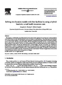
Fig. 1. Idealized inlet model research facility 共data from Seabergh et al. 2002兲.
methods for computing wave reflection and diffraction in the spectral wave models are discussed in a paper by Holthuijsen et al. 共2004兲. Both models were developed mainly for nearshore wave transformation and are not intended for predicting waves near structures. However, in numerous nearshore applications, coastal structures are commonly present and would affect the wave transformation nearby. It is well known that wave diffraction at the structure is beyond the capability of the wave action conservation equation. This limitation has been addressed by introducing ad hoc modifications of wave-structure interaction in some spectral wave models. These approximate treatments to account for wave diffraction in GHOST have been studied for simple structures on a sloping beach and flat bottom 共Carci et al. 2002; Rivero et al. 1997a, b兲. Similar studies have been conducted for STWAVE 共Resio 1993; Smith et al. 1999, 2001兲. Results of these studies are acceptable for simple structures. However, no comprehensive evaluation of these models has been conducted for complex structures at inlets. In this study, we have used a new set of wave data collected around an ideal tidal inlet in the laboratory 共Seabergh et al. 2002兲 as a benchmark to examine the overall skills of GHOST and STWAVE models for wave estimation in inlets. This extensive data set helped us reveal shortcomings of the two models with respect to wave structure and wave-current interactions, and helped us identify aspects of the numerical models for further improvement. The laboratory experiments were designed to obtain high-quality wave data in areas where wave-structure interaction is present on a sloping bottom near the jetties and breakwaters and in the bay behind an inlet. Fig. 1 shows the inlet model research facility. Wave-height data were collected by linear arrays of capacitance wave gauges 共Fig. 2兲. The directional spectrum was measured by a unique video-camera system designed to detect the intensity of light reflection on the surface waves 共Curtis et al. 2001, 2002兲. The video-camera system was capable of collecting spatial directional data synoptically over a large area. Similar video techniques have been developed during the past decade and applied in the coastal studies to measure variations in hydrodynamic processes 共Holman et al. 1993; Holland et al. 1997; Aarninkhof and Holman 1999兲. In the present study, the videocamera system was calibrated by using the in situ gauging system for wave height and acoustic-Doppler velocimeters 共ADV兲 for
STWAVE is a steady-state directional spectral wave model that implements a forward-marching explicit finite-difference method on a square-cell grid to solve the wave action conservation equation 共Resio 1981, 1987, 1988, 1993兲. The model is a half-plane model so that waves can propagate only from the seaward boundary toward the shoreline. Both nonlinear wave-wave interactions and depth/steepness-limited breaking are parameterized as the primary source/sink terms. A prespecified spectrum is required as the incident wave condition at the offshore boundary. The model can accept a homogeneous wind input and simulate wave-current interaction. Wave diffraction is approximately treated and represented in the model by smoothing of strong gradients in wave energy that occur in sheltered areas. The smoothing technique is grid-spacing dependent and uses 55% of energy at a center cell and 22.5% from two neighboring cells 共Smith et al. 1999, 2001兲. Wave reflection and bottom friction are neglected in STWAVE. GHOST, similar to STWAVE, is also a half-plane and steadystate directional wave spectral transformation model 共Rivero et al. 1997a, b; Carci et al. 2002兲. However, GHOST solves the wave action conservation equation with an implicit finite-difference method on a rectilinear grid. It also requires a prespecified wave spectrum as input at the offshore boundary. The model is capable of simulating wave-structure and wave-current interactions. GHOST can compute wave reflection, diffraction, and wave transmission through and over submerged structures. Bottom friction, wind input, and wave-wave interaction are neglected in the model. GHOST and STWAVE differ in several aspects. As was previously noted, GHOST adopts a marginal directional spectrum for wave transformation calculations, whereas STWAVE uses the full directional spectrum. GHOST represents wave diffraction by implementing a formulation of the Eikonal equation 共Rivero et al. 1997a, b兲, whereas STWAVE uses a spectral smoothing technique 共Resio 1993; Smith et al. 2001兲. Wave breaking in GHOST is based on the method of Battjes and Janssen 共1978兲. STWAVE uses empirical formulas of depth and steepness limitation 共Miche 1944兲 for its wave breaking. GHOST computes forward wave reflection 共in the wave propagation direction兲 from structures, whereas STWAVE neglects wave reflection. Forward wave reflection is treated in GHOST as a percentage increase of the local incident wave energy at cells in front of a structure. Therefore, with these differences between GHOST and STWAVE, we expected models to produce different results, especially in the vicinity of structures. Table 1 summarizes the main features of GHOST and STWAVE models. Fig. 3 shows a visual summary of GHOST and STWAVE simulations for waves around a shore-normal groin. This simple test demonstrates how differences in Table 1 between the two models would affect nearshore wave-height estimates near a coastal structure. In this example, the wave-wave interaction in STWAVE was turned off, since GHOST did not have the capability to model wave-wave interaction. The incident wave condition at the ocean boundary is a unidirectional JONSWAP spectrum of 1-m significant height 共defined as four times the square root of the total wave energy兲, with an 8 - s peak period and a 20° oblique angle to shore normal. It should be noted that even
150 / JOURNAL OF WATERWAY, PORT, COASTAL, AND OCEAN ENGINEERING © ASCE / JULY/AUGUST 2005
Fig. 2. Location map of wave gauges 共circle兲, rectangular area covered by video-camera system 共dotted line兲, and transect lines 共dashed line兲 for model and measured wave comparisons in the following configurations: 共a兲 S1; 共b兲 S2; 共c兲 S3; and 共d兲 S4
Table 1. Comparison of GHOST and STWAVE Capabilities Capability Spectrum 共half-plane兲 Refraction/shoaling Diffraction Wave-current Wave-wave interaction Wave breaking Reflection Wave transmission Wave energy loss by porous bottom Wave energy loss by bottom friction Wave generation
GHOST
STWAVE
Marginal directional Linear Equation Nonlinear None Battjes and Janssen 共1978兲 Forward reflection Linear Represented
Directional Linear Filtering Nonlinear Nonlinear Depth limitation, Miche 共1944兲 None None None
None
None
None
Wind input
incident waves are unidirectional and that waves can become multidirectional as they propagate into the shallow water toward the groin as a result of shoaling, refraction, diffraction, wave breaking, and so on. The predictions of GHOST with and without wave reflection are shown in Figs. 3共b and c兲, respectively. The STWAVE results are shown in Fig. 3共a兲. A reflection coefficient of 0.3 at the groin 共i.e., 30% reflection of wave energy兲 is used in the results depicted in Fig. 3共c兲. With wave reflection, GHOST predicts higher wave heights in the upwave side of groin compared with results without wave reflection. STWAVE results show little or no wave diffraction in the lee of the groin and exhibit more wave dissipation on the upwave side of the groin than the GHOST results.
Physical Model Historically, physical models were used for studying coastal inlets with complex bathymetry and protective structures such as jetties,
JOURNAL OF WATERWAY, PORT, COASTAL, AND OCEAN ENGINEERING © ASCE / JULY/AUGUST 2005 / 151
Fig. 3. Model wave results 共wave height contours in m, solid line兲 around an idealized groin 共bottom contours in m, dashed line兲: 共a兲 from STWAVE; 共b兲 from GHOST without reflection; and 共c兲 from GHOST with 30% reflection at the groin
breakwaters, and groins. With advanced techniques in numerical wave models to simulate wind waves, field and laboratory data are now collected primarily to validate such models. Previous laboratory studies of refraction and diffraction were made on a flat bottom, a sloping bottom, and on a flat bottom with a channel incised by two jetties 共Harms 1979; Hales 1980; Yu et al. 2000兲. In these earlier experiments, only wave height was measured. Since waves around coastal structures can turn substantially and change their direction, it was necessary to measure in both wave height and direction in these physical model experiments. An inlet physical model was designed to measure both wave height and direction 共Seabergh 1999; Seabergh et al. 2002兲 by using a 1:50 undistorted scale model. It was constructed to fit in a
46-m-wide by 99-m-long concrete basin with 0.6-m vertical walls 共Fig. 1兲. This scale replicates a medium-sized Atlantic coast inlet in the United States. The oceanside depth contours were parallel to straight shorelines. The beach slope was specified as an equilibrium profile 共Dean 1977兲, representing approximately a foreshore slope of 1 / 15 and an offshore slope of 1 / 50; and the model extended seaward to the prototype depth of 15 m. The inlet had an average prototype width of 133.4 m. The depth of the inlet throat converged to 7.6 m in prototype at the middle of inlet throat. The bay side floor was flat and had a prototype depth of 6.1 m. The physical model was capable of generating a steady-state flow to simulate either ebbing or flooding currents by using a
152 / JOURNAL OF WATERWAY, PORT, COASTAL, AND OCEAN ENGINEERING © ASCE / JULY/AUGUST 2005
Table 2. Ideal Inlet Experiments 共1:50 Scale兲 Experiment number
Wave direction 共degrees兲
Wave period, height, and type
Current on/off
共a兲 Configuration 1 共offshore breakwater parallel to shore兲 S1X4 S1X5 S1X6
20 20 20
5.7 s, 3.05 m, irregular wave 11.3 s, 2.30 m, irregular wave 5.7 s, 2.30 m, monochromatic wave
Off Off Off
共b兲 Configuration 2 共dogleg jetty at inlet兲 S2X1 S2X2 S2X3 S2X4 S2X5 S2X6
0 0 0 20 20 20
5.7 s, 3.05 m, irregular wave 11.3 s, 2.30 m, irregular wave 5.7 s, 3.05 m, monochromatic wave 5.7 s, 3.05 m, irregular wave 11.3 s, 2.30 m, irregular wave 5.7 s, 2.30 m, monochromatic wave
S3X1 S3X2 S3X3 S3X4 S3X5 S3X6
0 0 0 0 0 0
S4X1 S4X2 S4X3 S4X5 Note: Maximum flood current is 1.0 m / s
0 5.7 s, 3.05 m, irregular wave 0 11.3 s, 2.30 m, irregular wave 0 5.7 s, 2.30 m, monochromatic wave 0 11.3 s, 2.30 m, irregular wave at the inlet throat. Various wave/current conditions in the experiment are labeled as X1 to
Off Off Off Off Off Off
共c兲 Configuration 3 共bay measurements, natural inlet兲 5.7 s, 3.05 m, irregular wave 11.3 s, 2.30 m, irregular wave 5.7 s, 2.30 m, monochromatic wave 5.7 s, 3.05 m, irregular wave 11.3 s, 2.30 m, irregular wave 5.7 s, 2.30 m, monochromatic wave
Off Off Off On 共flood current兲 On 共flood current兲 On 共flood current兲
共d兲 Configuration 4, 共bay measurements, dual jetties at inlet兲
piping system. Fig. 1 shows the facility, piping/pump system, and one of the inlet configurations. A flap-hinge 24.4 m-long wave generator was used to produce regular or irregular unidirectional waves. The wave generator was movable so that it could be reoriented to specify an incident wave direction up to 45° shorenormal. At a Froude model scale of 1:50, prototype waves up to 3 m in height could be generated 共Hughes 1993兲. The inlet physical model was configured in four idealized “structural” arrangements. In order of presentation, the first is a shore-parallel semiinfinite offshore breakwater 共Configuration 1, or S1兲; the second, a dogleg jetty 共Configuration 2, or S2兲; the third, an inlet through two equal-width barrier islands without a stabilizing structure 共Configuration 3, or S3兲, which is designed to simulate diffraction through a gap; the fourth, a dual-jetty inlet 共Configuration 4, or S4兲 consisting of two equal-length jetties perpendicular to shore. Fig. 2 shows the four configurations in the prototype scale. In Configuration S1, the shore-parallel breakwater is located offshore at the depth contour of 6.8 m in the prototype. The breakwater extends 455 m in the prototype 共9.1 m in the physical model兲 from the sidewall of the physical model. In Configuration S2, the dogleg jetty consists of an inner segment perpendicular to the shore and an outer segment extending seaward at a 45° angle toward the inlet. The prototype lengths of the inner and outer segments are 280 and 265 m, respectively. In S4, two dual jetties, each 170 m long in the prototype, are oriented perpendicular to the straight shorelines of barrier islands. The experiments for the S1 and S2 configurations were designed for quantifying combined wave diffraction, refraction and shoaling caused by the sloping bottom, jetties, and breakwaters. The experiments for configurations S3 and S4 were designed to
Off Off Off On 共flood current兲 X6.
measure wave refraction and diffraction in the bay. Wave conditions used for all configurations consisted of two irregular waves and one regular wave. Two irregular waves represent a shortperiod wave 共mean period of 5.7 s in prototype兲 and a long-period wave 共mean period of 11.3 s兲. A flood current of the prototype velocity 1 m / s in the entrance channel was created by a piping/ pump system in the S3 and S4 experiments to simulate wavecurrent interaction. Ebbing currents were not tested in these experiments. Table 2 lists the experimental test conditions. Wave height was measured in situ with 20 wave gauges and remotely with a video-camera system. Wave direction was measured in situ with a pair of ADVs and the video camera system 共Curtis et al. 2001, 2002; Seabergh et al. 2002兲. Wave-height data collected from wave gauges are used in comparing model wave height. Wave direction measured by the ADVs served for checking the quality of the direction data measured by the video camera system. ADV versus video validation statistics for mean wave directions near the spectral peak shows good correlation between the two measurement techniques. Because the premise of the video system depends on the intensity of the reflected light, the measured wave energy density and direction by this system may be less accurate away from the spectral peak. Therefore, in this study, the wave direction at the spectral peak from the videocamera system is used in the comparison with numerical models. The measurement error in the spectral peak vector-mean wave direction is quantified by the standard deviation of the difference 共root-mean square, RMS, error兲 between ADV and video data. This error ranged from 4.6 to 13 degrees for four inlet configurations 共Seabergh et al. 2002兲.
JOURNAL OF WATERWAY, PORT, COASTAL, AND OCEAN ENGINEERING © ASCE / JULY/AUGUST 2005 / 153
Performance of Numerical Wave Models In the present study, simulations made with GHOST and STWAVE are based on the same numerical grid. It consisted of 180 共along-shore direction兲 ⫻160 共across-shore direction兲 square cells. Although the performance of GHOST could be improved by using rectangular cells in areas of high wave gradients 共Carci et al. 2002兲, the STWAVE grid was used in GHOST for a fair comparison of the models. Each cell was 10⫻ 10 m in the prototype, and the model grid represented an area of 1.8⫻ 1.6 km. The modeling domain extended 940 m to the left of the inlet and 730 m to the right, 790 m offshore to a depth contour of 15 m, and 570 m bayward of the two barrier islands. Inlet width was 130 m 共13 cells兲. A JONSWAP-type unidirectional wave spectrum was input 共30 frequency bins and 35 direction bins兲 at the offshore boundary of both wave models. Standard JONSWAP spectral parameters were used 共Goda 1985兲. The peak enhancement factor 共gamma兲 was set to 3.3 and 200 to represent irregular and monochromatic waves, respectively. In the GHOST model, we used a value of 0.1 for the reflection coefficient for jetties and shorelines of the inlet in an attempt to simulate wave reflection observed in the physical model. Fig. 2 presents the location of wave gauges 共circles兲, the jetties and breakwater structures, the rectangular area 共dotted line兲 covered by the video-camera system, and transects 共dashed line兲 for comparing calculations and measurements. In each modeling configuration, transects T1–T6 were selected for the comparison, with three shore-parallel and three shore-normal transects. For irregular waves, calculated and measured wave heights were the significant height. For monochromatic waves, the mean wave height was used. The modeling condition is denoted by SnXm, where n = 1 , 2 , 3 , 4 共inlet configuration number兲 and where m = 1 , 2 , 3 , 4 , 5 , 6 共incident wave and current condition number兲. For example, S1X4 represents the experiment for inlet configuration S1 with incident wave condition X4. Hereafter, wave height refers to significant height for irregular wave input condition and wave direction refers to mean wave direction 共calculated as the mean direction from the directional spectrum兲. For wave-current interaction numerical simulations, the current field was computed from a circulation model ADCIRC 共Luettich et al. 1992兲, which was calibrated with dye tests and which measured ADV currents at the inlet.
Comparisons for Configuration S1 The S1 experiments were designed for diffraction by a detached breakwater and were conducted for three incident wave conditions: an irregular short wave 共X4兲, an irregular long wave 共X5兲, and a monochromatic wave 共X6兲 with 20° oblique incident wave direction to shore-normal for all conditions. Fig. 4 shows the comparison of calculated and measured significant wave heights and mean directions along the six transects 共see Fig. 3兲 for the incident wave condition X4. The RMS error in the measured spectral peak wave direction, quantified by the standard deviation of the difference between ADV and video data, is 4.6° for S1 experiments 共Seabergh et al. 2002兲. GHOST results along T1, T2, and T6 in Fig. 4 are in good agreement with the data, especially in the area behind the breakwater. Otherwise, the performance of the two models is similar. STWAVE predicted wave heights of zero along parts of T1 behind the breakwater. The wave direction associated with these zero wave heights was excluded in the model and data comparison statistics in Tables 3–6. Both models per-
formed poorly for cross-shore transects T3 and T5. Overall, GHOST estimates of wave height and direction are in good agreement with the data for test conditions X4–X6.
Comparisons for Configuration S2 Configuration S2 has a dogleg jetty with the first segment normal to shoreline followed by a second segment aligned approximately 45° from the first segment and pointing toward the inlet. The S2 experiments used six incident wave conditions, X1–X6 共see Table 2兲. The incident wave direction was shore-normal in X1–X3, and 20° shore-normal in X4–X6. Predicted and measured wave height and direction were compared along six transects 共T1–T6兲, covering the shallow areas shoreward of the jetty 共see Fig. 3兲. Fig. 5 illustrates the comparison of calculated wave height and wave direction with data along the six transects for the incident wave condition X4. The RMS error in the measured spectral peak wave direction for S2 experiments was 7.0° 共Seabergh et al. 2002兲. Along T1, at the seaward end of the jetty parallel to the shoreline, GHOST and STWAVE show good agreement with wave height and direction data for all incident waves. Both models tend to significantly underpredict wave height along T2–T6, especially in the area behind the jetty where waves are diffracted shoreward by the dogleg jetty. For short-period irregular waves 共X1 and X4兲, STWAVE performed well as compared with data in terms of the predicted wave height. In contrast, for shore-normal long-period irregular waves 共X2兲 and monochromatic waves 共X3兲, GHOST performed well for wave height as compared with the data. For wave direction, GHOST generally performed well for oblique incident waves but was less accurate for shore-normal incident waves.
Comparisons for Configuration S3 Configuration S3 is an ideal natural inlet without any navigationaiding structures. The physical model experiments consisted of six incident wave and current conditions, all with shore-normal incident wave direction. Test conditions X1–X3 were designed for experiments under the incident waves only in the inlet, whereas conditions X4–X6 included a steady flood flow to study combined wave and current effects. Fig. 6 compares calculated and measured wave height and direction along six transects 共T1– T6兲 located in the bay side of the inlet for test condition X3 共see Fig. 3兲. The RMS error in the measured spectral peak wave direction for S3 experiments was 13° 共Seabergh et al. 2002兲. Fig. 6 shows the predicted wave height and direction from GHOST; they are in agreement with the data. In this case, STWAVE consistently underpredicted wave heights in the inlet and in the bay. The laboratory experiments indicated a stronger diffraction than model predictions in the bay for all six tested conditions, with or without a flood current.
Comparisons for Configuration S4 The dual-jetty S4 inlet experiments were conducted for four incident wave and current conditions: X1–X3 and X5. The incident wave direction was shore-normal. A sample comparison of the calculated and measured wave height and direction along six transects 共T1–T6兲 located in the bay behind the inlet for X3 is shown in Fig. 7. The RMS error in the measured spectral peak wave direction for S4 experiments was 7.7° 共Seabergh et al. 2002兲. The predicted wave heights from GHOST agreed well with the measurements in Fig. 7, whereas STWAVE underestimated
154 / JOURNAL OF WATERWAY, PORT, COASTAL, AND OCEAN ENGINEERING © ASCE / JULY/AUGUST 2005
Fig. 4. Model versus measured wave height and direction for S1X4
wave heights along all six transects. GHOST also produced slightly better wave-direction estimates than STWAVE did. For long-period irregular waves 共X2兲, GHOST results for wave heights compared well with the data. However, the model overpredicted wave heights for short-period irregular waves 共X1兲. Both models underestimated wave height for long-period irregular waves with a flood current 共X5兲. STWAVE underestimated wave height along six transects for all four tested incident wave conditions. As compared with the data, both models generally
failed to predict wave direction accurately for Configuration S4. Measurements showed stronger wave diffraction in the bay than wave models did, both with and without a flood current.
Discussion of Results Two statistical parameters are used in evaluating the overall performance of numerical wave models: 共1兲 the mean of the absolute
JOURNAL OF WATERWAY, PORT, COASTAL, AND OCEAN ENGINEERING © ASCE / JULY/AUGUST 2005 / 155
Table 3. Statistical Mean Errors of Model Wave Height and Direction for Configuration S1 Experiment number
Mean of absolute relative wave height error 共%兲
Mean of absolute direction error 共degrees兲
Table 5. Statistical Mean Errors of Model Wave Height and Direction for Configuration S3 Experiment number
共a兲 GHOST S1X4 S1X5 S1X6 Average
20.2 20.8 24.7 21.9
25.4 28.3 35.4 29.7
5.5 5.3 4.6 5.1
8.3 6.5 8.3 7.7
relative error for wave height, defined as the percent change of model and measured wave height 共i.e., 100 percent⫻ 兩predicted − measured兩 / measured兲; and 共2兲 the mean of the absolute difference of model and measured wave direction. These statistical parameters were calculated for each numerical model, and data along transect lines were preselected for each of the four inlet configurations. Since the peak period did not change in either the physical or numerical models, the wave period was not considered in our comparison of model results and data. Tables 3–6 present statistical comparisons for configurations S1–S4, respectively. The statistics shown are averaged values of all alongshore and cross-shore transects for each experimental condition for a given inlet configuration. The averaging was performed for both wave height and direction. Because STWAVE predicted zero wave height behind the breakwater in Configuration S1, the wave direction associated with the zero height was excluded from the calculated statistics. Since the performance of the models varied with the incident wave conditions, describing the model performance specifically
Table 4. Statistical Mean Errors of Model Wave Height and Direction for Configuration S2 Experiment number
Mean of absolute relative wave height error 共%兲
Mean of absolute direction error 共degrees兲
共a兲 GHOST S2X1 S2X2 S2X3 S2X4 S2X5 S2X6 Average
40.8 30.3 33.8 54.6 37.2 40.7 39.6
12.5 8.8 11.5 12.2 7.8 10.2 10.5
共b兲 STWAVE S2X1 S2X2 S2X3 S2X4 S2X5 S2X6 Average
38.9 40.3 37.7 37.8 40.3 31.3 33.1
Mean of absolute direction error 共degrees兲
共a兲 GHOST
共b兲 STWAVE S1X4 S1X5 S1X6 Average
Mean of absolute relative wave height error 共%兲
11.5 9.2 10.7 15.1 11.7 15.1 12.2
S3X1 S3X2 S3X3 S3X4 S3X5 S3X6 Average
15.9 35.1 28.5 24.8 19.2 30.9 25.7
6.4 6.3 4.6 6.3 9.4 5.5 6.4
共b兲 STWAVE S3X1 S3X2 S3X3 S3X4 S3X5 S3X6 Average
39.6 36.6 39.1 28.2 25.3 51.3 36.7
7.3 7.0 5.2 6.0 8.8 5.1 6.6
for regular and irregular waves is necessary. For monochromatic waves 共X3 and X6兲, the errors in wave-height statistics ranged from 24.7 to 40.7% for GHOST and from 35.4 to 51.3% for STWAVE in all inlet configurations 共S1 to S4兲. For short-period irregular waves 共X1 and X4兲 in Configurations S1 and S3, the errors in wave-height estimates were 15.9 to 24.8% versus 25.4 to 39.6%, respectively, for GHOST and STWAVE. In these cases, GHOST seemed to perform better. In contrast, STWAVE performed better for short-period irregular waves 共X1 and X4兲 in S2 and S4, since the errors in wave-height estimates were 34.9 to 54.6% versus 23.4 to 38.9%, respectively, for GHOST and STWAVE. For long-period irregular waves 共X2 and X5兲, the errors in wave-height estimates varied from 19.2 to 44.5% versus 25.3 to 50.1%, respectively, for GHOST and STWAVE for all configurations 共S1 to S4兲. In this case, GHOST performance was slightly better than STWAVE in predicting wave heights for long-period
Table 6. Statistical Mean Errors of Model Wave Height and Direction for Configuration S4 Experiment number
Mean of absolute relative wave height error 共%兲
Mean of absolute direction error 共degrees兲
共a兲 GHOST S4X1 S4X2 S4X3 S4X5 Average
34.9 21.8 18.9 44.5 30.0
5.0 9.3 5.7 9.2 7.3
共b兲 STWAVE S4X1 S4X2 S4X3 S1X5 Average
23.4 34.3 46.3 50.1 38.5
156 / JOURNAL OF WATERWAY, PORT, COASTAL, AND OCEAN ENGINEERING © ASCE / JULY/AUGUST 2005
5.0 10.1 6.4 9.0 7.6
Fig. 5. Model versus measured wave height and direction for S2X4
irregular waves. The overall mean errors in wave height of all test conditions for the four configurations varied from 22 to 40% for GHOST and from 30 to 39% for STWAVE. Therefore, GHOST seems to perform well for wave-height predictions. The statistics for wave direction 共Tables 3–4兲 indicate that GHOST produced consistently more reliable wave-direction estimates in the lee of jetties and breakwaters 共S1 and S2兲. For Configuration S1, the errors in wave direction varied from 4.6 to 5.5° and from 6.5 to 8.3°, respectively, for GHOST and STWAVE. For S2, the errors were 7.8 to 12.5% for GHOST, and 9.2 to 15.1° for
STWAVE. Both models produced similar wave direction in the inlet channel and in the bay for Configurations S3 and S4. For S3, the errors in wave direction were 4.6 to 9.4° for GHOST versus 5.1 to 8.8° for STWAVE. For S4, the errors were 5.0 to 9.3° for GHOST versus 5.0 to 10.1° for STWAVE. The statistical results of model wave direction for Configurations S1 and S2 are more meaningful, since instrumental error of the video-camera system for these configurations was relatively small 共4.6° for S1 and 7° for S2兲. In contrast, for S3 and S4, the statistics of wave direction are less reliable, since instrumental error 共13° for S3 and 7.7° for
JOURNAL OF WATERWAY, PORT, COASTAL, AND OCEAN ENGINEERING © ASCE / JULY/AUGUST 2005 / 157
Fig. 6. Model versus measured wave height and direction for S3X3
S4兲 was equal to or greater than the error in wave-direction estimates. The difference between model results is mainly attributable to three factors: 共1兲 different representation and transformation of the directional wave spectrum; 共2兲 different treatments of wave diffraction and reflection; and 共3兲 different implementation of wave breaking criteria used in each model. The treatment of wave-current interaction in these models is also a potential cause for differences in model performance. Wave-induced currents 共not
simulated in the present study兲 may contribute to the difference between model results and data. Additional studies are necessary to determine the appropriateness of wave breaking and dissipation implemented in wave models. The physical model results showed a nonuniform wave-height distribution of waves entering and exiting the inlet that was due to wave shoaling, reflection, refraction, and diffraction. Neither model was capable of capturing these combined wave processes in inlets. Models did not show excessive bending or turning of
158 / JOURNAL OF WATERWAY, PORT, COASTAL, AND OCEAN ENGINEERING © ASCE / JULY/AUGUST 2005
Fig. 7. Model versus measured wave height and direction for S4X3
waves to the extent seen in the physical model tests 共Figs. 6 and 7兲. Waves in the bay dissipated and decayed more rapidly in STWAVE simulations, causing the model to consistently underestimate wave heights in the bay. Since GHOST considers wave reflection, it provided slightly better wave-height prediction in the bay. In the dual-jetty inlet configuration with a flood current 共S4X5兲, both models performed poorly as compared with the data. Models showed excessive dissipation attributable to wave
breaking and wave-current interaction inside the inlet. Models performed similarly for a natural inlet configuration 共S3兲 with a flood current, suggesting that models do not perform well under wave-current interactions in inlets. The model results also showed a significant reduction of wave energy prior to waves entering inlets for both regular and irregular waves 共Figs. 6 and 7兲. This excessive wave-energy reduction can affect model results in the inlet and bay. Such excessive reduction of energy is suspected to be caused by wave-breaking criteria implemented in the models.
JOURNAL OF WATERWAY, PORT, COASTAL, AND OCEAN ENGINEERING © ASCE / JULY/AUGUST 2005 / 159
Additional studies are necessary to determine the appropriateness of wave-breaking formulas used in models.
Conclusions The evaluation of the two numerical wave models, GHOST and STWAVE, is presented by comparing their performance with a new and extensive set of laboratory data for four idealized tidal inlet configurations on a sloping beach: a detached breakwater, a dogleg breakwater, a natural inlet 共without jetties兲, and an inlet with dual jetties. We treated the numerical models as “black boxes” in this evaluation, with the objective of determining their predictive skills for estimating waves in coastal inlets. Overall, the performance of the two models was similar, but neither was satisfactory or overwhelmingly better than the other. For the GHOST model, the mean absolute relative error in wave height ranged from 22 to 40% in the four inlet configurations. The error in STWAVE wave-height estimates varied from 30 to 39% The mean absolute error in wave direction was 5.1 to 10.5° for GHOST and 6.6 to 12.2° for STWAVE. The performance of GHOST showed less error in wave height compared with STWAVE in three of the four inlet configurations 共S1, S3, and S4兲. The mean absolute error in wave-direction by both models was similar in magnitude. Wave-direction estimates by GHOST were generally in better agreement with data. The emphasis in the present evaluation of GHOST and STWAVE models was focused on the models’ performance around structures 共i.e., jetties or breakwaters兲 at inlets and in the bay. Models were evaluated for four inlet configurations with different incident wave conditions. The errors in wave height and direction from GHOST for monochromatic waves were generally less than those for STWAVE. For irregular waves, the overall performance of GHOST was similar to STWAVE and only slightly better. However, neither model was able to accurately predict waves at inlets in the vicinity of structures and in the bay. Both models tend to underpredict wave height for all four inlet configurations 共Figs. 4–6兲. Both models were unable to capture the turning of waves in areas where waves interact with currents and structures. The model results showed a noticeable underestimation in the wave height seaward of the inlet. This underestimation may have resulted from neglecting wave scattering and from inadequate treatment of wave-current interaction and wave breaking in inlets. Further investigations of wave breaking and wavecurrent interaction near inlets are necessary for improving spectral wave models in inlet applications. Since GHOST treats wave diffraction and reflection in a more comprehensive fashion, it is able to provide wave height and direction estimates that are in better agreement with the data. GHOST has additional features for wave transmission over permeable and through porous structures in inlets. STWAVE has additional capability for wind input and wave-wave interaction. These unique features of the models were not investigated in the present study. The comprehensive wave data sets used in this paper are valuable in developing and evaluating of wave models. Work is presently under way to vigorously improve STWAVE capabilities for wave diffraction and reflection.
Acknowledgments William Seabergh provided the laboratory data and assisted in the model evaluation study. Nicholas Kraus provided encouragement
and helpful comments on this paper. William Seabergh conducted experiments, and provided data and helped in comparison of models with data. This work was performed under the Inlet Modeling System Work Unit of the Coastal Inlets Research Program, U.S. Army Corps of Engineers. Permission to publish this paper was granted by the Chief, USACE.
References Aarninkhof, S., and Holman, R. A. 共1999兲. “Monitoring the nearshore with video.” Backscatter, 5共11兲, 8–11. Battjes, J. A., and Janssen, J. P. F. M. 共1978兲. “Energy loss and set-up due to breaking of random waves.” Proc., 16th Int. Coastal Engineering Conf., Hamburg, Germany, 569–587. Carci, E., Rivero, F. J., Burchart, H. Y., and Maciñeira, E. 共2002兲. “The use of numerical modeling in the planning of physical model test in a multidirectional wave basin.” Proc., 28th Int. Coastal Engineering Conf., Cardiff, U.K., 485–494. Cialone, M. A., and Kraus, N. C. 共2001兲. “Wave Transformation at Grays Harbor, WA, with strong currents and large tide range.” Proc., 4th Int. Symp. of Ocean Wave Measurement and Analysis, Waves 2001, Vol. 1, ASCE, Reston, Va., 794–803. Curtis, W. R., Hathaway, K. K., Holland, K. T., and Seabergh, W. C. 共2002兲. “Video-based direction measurements in a scale physical model.” Technical Note ERDC/CHL CHETN-IV-49, U.S. Army Engineer Research and Development Center, Vicksburg, Miss. Curtis, W. R., Hathaway, K. K., Seabergh, W. C., and Holland, K. T. 共2001兲. “Measurement of physical model wave diffraction patterns using video.” Proc., 4th Int. Symp. of Ocean Wave Measurement and Analysis, Waves 2001, Vol. 1, ASCE, Reston, Va., 23–32. Dean, R. G. 共1977兲. “Equilibrium beach profiles: U.S. Atlantic and Gulf Coasts.” Ocean Engineering Technical Rep. No. 12, Dept. of Civil Engineering and College of Marine Studies, Univ. of Delaware, Newark, Del. Demirbilek, Z., and Panchang, V. 共1998兲. “CGWAVE: A coastal surfacewater wave model of the mild-slope equation.” Technical Rep. CHL98-26, U.S. Army Engineer Waterways Experiment Station, Vicksburg, Miss. Goda, Y. 共1985兲. Random seas and design of maritime structures, University of Tokyo Press, Tokyo. Hales, L. Z. 共1980兲. “Erosion control of scour during construction.” Technical Rep. HL-80-3, U.S. Army Engineer Waterways Experiment Station, Vicksburg, Miss. Harms, V. W. 共1979兲. “Diffraction of waves by shore-connected breakwater.” J. Hydraul. Div., Am. Soc. Civ. Eng., 105共12兲, 1501–1519. Holland, K. T., Holman, R. A., Lippman, T. C., Stanley, J., and Plant, N. 共1997兲. “Practical use of video imagery in nearshore oceanographic field studies.” IEEE J. Ocean. Eng. 22共1兲, 81–92. Holman, R. A., Sallenger, A. H., Lippmann, T. C., and Haines, J. W. 共1993兲. “The application of video image processing to the study of nearshore processes.” Oceanography, 6共3兲, 78–85. Holthuijsen, L. H., Herman, A., and Booij, N. 共2004兲. “Phase-decoupled refraction-diffraction for spectral wave models.” J. Coastal Engineering, 49, 291–305. Hughes, S. A. 共1993兲. Physical models and laboratory techniques in coastal engineering, World Scientific, River Edge, N.J. Luettich, R. A., Westerink, J. J., and Scheffner, N. W. 共1992兲. “ADCIRC: An advanced three-dimensional circulation model for shelves, coasts and estuaries; Report 1: Theory and methodology of ADCIRC-2DDI and ADCIRC-3DL.” Technical Rep. DRP-92-6, U.S. Army Engineer Waterways Experiment Station, Vicksburg, Miss. Massel, S. R. 共1993兲. “Extended refraction-diffraction equation for surface waves.” J. Coastal Engineering, 19, 97–126. Mei, C. C. 共1983兲. The applied dynamics of ocean surface waves, Wiley, New York.
160 / JOURNAL OF WATERWAY, PORT, COASTAL, AND OCEAN ENGINEERING © ASCE / JULY/AUGUST 2005
Miche, R. 共1944兲. “Undulatory movements of the sea in constant and decreasing depth.” Ann. Ponts Chaussees, 25–78, 131–164, 270–292, 369–406 共in French兲. Panchang, V., Xu, B., and Demirbilek, Z. 共1999兲. “Chapter 4: Wave prediction models for coastal engineering applications.” Developments in Offshore Engineering, J. B. Herbich, ed., Gulf Pub., Houston, 163– 194. Penney, W. G., and Price, A. T. 共1952兲. “The diffraction theory of sea waves by breakwaters, and shelter afforded by breakwaters.” Philos. Trans. R. Soc. London, Ser. A, 244, 236–253. Resio, D. T. 共1981兲. “The estimation of wind-wave generation in a discrete spectral model.” J. Phys. Oceanogr., 11, 510–525. Resio, D. T. 共1987兲. “Shallow water waves. I: Theory.” J. Waterw., Port, Coastal, Ocean Eng., 113, 264–281. Resio, D. T. 共1988兲. “Shallow water waves. II. Data Comparisons.” J. Waterw., Port, Coastal, Ocean Eng., 114, 50–65. Resio, D. T. 共1993兲. “STWAVE: Wave propagation simulation theory, testing, and application.” Tech. Rep., Florida Institute of Technology, Melbourne, Fla. Rivero, F. J., Arcilla, A. S., and Carci, E. 共1997a兲. “Implementation of diffraction effects in the wave energy conservation equation.” IMA Conf. on Wind-Over-Waves Couplings: Perspectives and Prospects, April 8–10, 1997, The Univ. of Salford, U.K.
Rivero, F. J., Arcilla, A. S., and Carci, E. 共1997b兲. “An analysis of diffraction in spectral wave models.” Proc., 3rd Int. Symp. of Ocean Wave Measurement and Analysis, Waves 97, Vol. 1, ASCE, Reston, Va., 431–445. Seabergh, W. C. 共1999兲. “Physical model for coastal inlet entrance studies.” Coastal Engineering Technical Note CETN-IV-19, U.S. Army Engineer Research and Development Center, Vicksburg, Miss. Seabergh, W. C., Curtis, W. R., Thomas, L. J., and Hathaway, K. K. 共2002兲. “Physical model study of wave diffraction-refraction at an idealized inlet.” Coastal Inlet Research Program, Technical Rep. ERDC/CHL-TR-02-27, U.S. Army Engineer Research and Development Center, Vicksburg, Miss. Smith, J. M., Resio, D. T., and Zundel, A. K. 共1999兲. “STWAVE: Steadystate spectral wave model.” Instruction Rep. CHL-99-1, U.S. Army Engineer Waterways Experiment Station, Vicksburg, Miss. Smith, J. M., Sherlock, A. R., and Resio, D. T. 共2001兲. “STWAVE: Steady-state spectral wave model user’s manual for STWAVE.” Version 3.0. Special Rep. ERDC/CHL SR-01-1, U.S. Army Engineer Research and Development Center, Vicksburg, Miss. Yu, Y.-X., Liu, S.-X., Li, Y. S., and Wai, O. W. H. 共2000兲. “Refraction and diffraction of random waves through breakwater.” Ocean Eng., 27, 489–509.
JOURNAL OF WATERWAY, PORT, COASTAL, AND OCEAN ENGINEERING © ASCE / JULY/AUGUST 2005 / 161