View Article Online View Journal
Lab on a Chip Accepted Manuscript
This article can be cited before page numbers have been issued, to do this please use: D. Kinahan, S. M. Kearney, N. Dimov, M. T. Glynn and J. Ducree, Lab Chip, 2014, DOI: 10.1039/C4LC00380B.
This is an Accepted Manuscript, which has been through the Royal Society of Chemistry peer review process and has been accepted for publication. Accepted Manuscripts are published online shortly after acceptance, before technical editing, formatting and proof reading. Using this free service, authors can make their results available to the community, in citable form, before we publish the edited article. We will replace this Accepted Manuscript with the edited and formatted Advance Article as soon as it is available. You can find more information about Accepted Manuscripts in the Information for Authors. Please note that technical editing may introduce minor changes to the text and/or graphics, which may alter content. The journal’s standard Terms & Conditions and the Ethical guidelines still apply. In no event shall the Royal Society of Chemistry be held responsible for any errors or omissions in this Accepted Manuscript or any consequences arising from the use of any information it contains.
www.rsc.org/loc
Page 1 of 10
Lab on a Chip
►
View Article Online
Lab on a Chip
DOI: 10.1039/C4LC00380B
PAPER
David J. Kinahan*a,b, Sinéad M. Kearney a,b, Nikolay Dimov a,b,c, Macdara T. Glynn a,b, and Jens Ducrée*a,b 5
10
15
20
25
Received (in XXX, XXX) Xth XXXXXXXXX 20XX, Accepted Xth XXXXXXXXX 20XX DOI: 10.1039/b000000x The centrifugal “lab-on-a-disc” concept has proven to have great potential for process integration of bioanalytical assays, in particular where ease-of-use, ruggedness, portability, fast turn-around time and cost efficiency are of paramount importance. Yet, as all liquids residing on the disc are exposed to the same centrifugal field, an inherent challenge of these systems remains the automation of multi-step, multiliquid sample processing and subsequent detection. In order to orchestrate the underlying bioanalytical protocols, an ample palette of rotationally and externally actuated valving schemes has been developed. While excelling with the level of flow control, externally actuated valves require interaction with peripheral instrumentation, thus compromising the conceptual simplicity of the centrifugal platform. In turn, for rotationally controlled schemes, such as common capillary burst valves, typical manufacturing tolerances tend to limit the number of consecutive laboratory unit operations (LUOs) that can be automated on a single disc. In this paper, a major advancement on recently established dissolvable film (DF) valving is presented; for the very first time, a liquid handling sequence can be controlled in response to completion of preceding liquid transfer event, i.e. completely independent of external stimulus or changes in speed of disc rotation. The basic, event-triggered valve configuration is further adapted to leverage conditional, large-scale process integration. First, we demonstrate a fluidic network on a disc encompassing 10 discrete valving steps including logical relationships such as an AND-conditional as well as serial and parallel flow control. Then we present a disc which is capable of implementing common laboratory unit operations such as metering and selective routing of flows. Finally, as a pilot study, these functions are integrated on a single disc to automate a common, multi-step lab protocol for the extraction of total RNA from mammalian cell homogenate.
1. Introduction
30
35
40
45
On centrifugal microfluidic platforms, a typically disc-shaped cartridge, with geometry similar to a conventional optical data storage media such as Compact Disc (CDTM) or Digital Video / Versatile Disc (DVDTM), is rotated at defined frequencies by a spindle motor to implement flow control and particle separation. Unlike most pressurised lab-on-a-chip devices, the pumping force can easily be varied over 4 to 5 orders of magnitude without fluidic connectors between the chip and the periphery, thus notably simplifying device set-up, operation and maintenance. The independence of the centrifugal field from internal or external pumping sources makes the “lab-on-a-disc” concept well suited to autonomous point-of-care / point-of-use applications, particularly where user-friendliness, speed and cost are important. Over the past decade, these centrifugal microfluidic technologies 1-2 have made significant progress towards automating and parallelizing sample preparation and downstream detection of bioanalytical assays in areas such as biomedical diagnostics 3, bioprocess monitoring 4 and environmental screening 5-6. This journal is © The Royal Society of Chemistry [year]
50
55
60
65
The mainstays of the lab-on-a-disc concept are the valving techniques which enable and co-ordinate essential LUOs 7 such as metering, mixing, and reagent release. One can distinguish between innate, rotationally controlled and externally actuated valving schemes. The latter typically involve sacrificial materials which transiently block the fluidic channels. The barrier is removed by techniques such as electromagnetic irradiation 8-9 and / or heating of phase-change materials such as ferro-wax 10-12. Also, external pressure sources 5 and methods based on physical contact have been employed for flow control 13. In general, external actuation strategies offer greater flexibility; typically, however, at the expense of more complex disc fabrication and support instrumentation. The more established rotationally actuated (passive) valves often rely on the interplay between capillary forces and the centrifugally induced hydrostatic pressure. Depending upon whether they yield with increasing or decreasing frequencies of rotation, they can be categorized as high-pass or low-pass valves, respectively. In the common high-pass capillary burst valve 14-18, the rotationally induced hydrostatic pressure is balanced by the [journal], [year], [vol], 00–00 | 1
Lab on a Chip Accepted Manuscript
Published on 25 April 2014. Downloaded by Dublin City University on 30/04/2014 18:33:03.
Event-Triggered Logical Flow Control for Comprehensive Process Integration of Multi-Step Assays on Centrifugal Microfluidic Platforms
5
Published on 25 April 2014. Downloaded by Dublin City University on 30/04/2014 18:33:03.
10
15
20
25
30
35
40
45
50
55
counteracting pressure arising at capillary barriers such as hydrophobic constriction or hydrophilic expansions. Beyond a critical burst frequency (governed by the cross section of the channel, the radial position and extension of the liquid plug, the local contact angle and surface tension) the hydrostatic pressure prevails to open the valve 18. In practice, manufacturing tolerances smear the geometrically defined burst frequencies into bands while the minimum achievable feature size imposes an upper frequency limit above which these valves will not function. These effects can restrict the number of sequential LUOs that can be automated using these valves 19. In practise, the actuation frequencies of other high-pass valving technologies, such as burstable foils 20, elastomeric membranes 21, and dead-end pneumatic chambers 22, are also best described as frequency bands, rather than specific frequencies, due to often significant variation of their yield point. Siphons are the most common representative of rotationally actuated low-pass valves. Reducing the disc spin rate allows the capillary pressure in the inbound part of the hydrophilic siphon to surpass the counteracting centrifugal body force, thus driving the liquid meniscus radially inward and then around the siphon crest. Hydrostatic pumping is initiated once the meniscus passes radially outward of the equilibrium liquid level 4, 23-24. The hydrophilicity of surfaces tends to markedly attenuate over time; therefore more robust priming mechanisms have been developed. For instance, centrifugo-pneumatically actuated siphons release energy stored in gas compressed during high-frequency loading to pneumatically prime, when the spin rate is reduced, even (slightly) hydrophobic siphon channels 25-26. However, proper operation of centrifugo-pneumatic siphoning is tightly connected to vigorous rotational acceleration and deceleration ramps, and thus can require powerful spindle motors. While high-pass and low-pass valves have been concatenated to increase the number of LUOs which can theoretically be implemented to an extent only limited disc real-estate 4,23, in practice this hybrid scheme tends to be quite complex and unreliable. Gorkin et al. 19 paired a (water) dissolvable film (DF) with a pneumatic chamber 22 to establish a new type of rotationally triggered high-pass valve. In this rotationally actuated scheme, a gas pocket is created between the restrained main liquid and the DF. The gas pressure in this pneumatic chamber combined with capillary effects initially prevents the liquid from contacting the DF. Beyond a critical burst frequency, the hydrostatic pressure prevails and the liquid enters the pneumatic chamber. It then contacts and dissolves the film to open the valve. As they are primarily dependant on the volume of the pneumatic chamber, the burst frequency of these DF valves can be tuned over a considerably wider range than other high-pass burst valves. However, while these valves represent a major advancement in the state of the art, manufacturing tolerances still smear the burst frequencies into wide bands 27 and so limit the number of discrete LUOs which can be implemented. Ukita et al. 28 introduced an internally triggered valving scheme which functions in a sequential manner at a constant disc spin rate. After loading, gas pockets are generated between two liquid elements which are restrained by this airlock. Pumping / movement of one of these liquid elements vents the airlock, thus inducing the subsequent release of the second liquid. While pro-
60
65
70
75
80
85
90
95
100
View Article Online
Page 2 of 10
DOI: 10.1039/C4LC00380B
mising, the authors report that the times for triggering multiple valves are of the order of 10 s; therefore are not yet compatible with typical bioanalytical protocols which often require minute time scales. In this paper, a novel paradigm is brought to centrifugal microfluidic flow control. The underlying valving technology may be considered analogous to a single-use (sacrificial), normally open electrical relay. The valving technology utilizes the arrival of an ancillary liquid at one location on the disc to prompt the release of another liquid residing at another, distant location on the disc by means of a connecting pneumatic channel. This eventtriggered mechanism enables, for the first time, cascading a multi-step liquid handling sequence which is independent of the disc rotational frequency. Thus the number of sequential assay steps that can be concatenated is now only curtailed by available disc real-estate. Additionally, as valve actuation is initiated by dissolving a sacrificial material, rather than by changing the disc spin rate, the mechanism is less sensitive to manufacturing tolerances and surface treatments than rotationally actuated valves. Furthermore, these valves can be configured into networks to implement conditional operations analogous to an electrical network, such as AND / OR relationships. Similarly, it is possible to actuate several valves in parallel. This new flow control scheme is highly suitable for application to the multi-step, sequential wash protocols common in biomedical diagnostics. In this paper, this valving technology is introduced and a number of microfluidic structures are employed to illustrate the operational principles and capabilities of the valves. First, a fluidic network is shown which encompasses 10 discrete valving steps, thus demonstrating network function such as sequential and parallel actuation, AND-condition actuation and LUOs such as batch-mode mixing. A microfluidic structure is then presented which showcases the capability of the valves to implement multistep liquid handling protocols. This cartridge provides automatic metering, sequential liquid release / washing using AND-condition valves and selective routing of reagent flows. This cartridge design is then modified and used, as a proof-of-concept, for the full automation of a multi-step, solid-phase purification of total RNA from chemically lysed 29 MCF7 breast cancer cell homogenate.
2. Valve Principles 2.1 Generalised Event-Triggered Valve Geometry
105
110
In previous iterations of on-disc DF-based flow control 19, valves were actuated by increasing the disc spin rate. This compressed gas trapped between the advancing liquid and the DF; resulting in the DF being wetted, dissolved and the valve opened. In the basic form of the event triggered valve (Fig. 1a-c), the structure consists of a pneumatic chamber sealed by the restrained main liquid and two DFs; which, continuing the analogy of the electrical relay, are referred to as the control film (CF) and load film (LF). Dissolving the CF by means of an ancillary liquid vents the pneumatic chamber, permitting the main liquid to advance and to wet and then dissolve the LF. The main liquid now exits through the newly created opening. This pneumatic chamber is shaped such that, under typical spin
Lab on a Chip Accepted Manuscript
Lab on a Chip
5
10
15
20
25
30
View Article Online
Lab on a Chip
DOI: 10.1039/C4LC00380B
Fig. 1 Representative schematics of the (a-c) basic event triggered valve geometry and (d-f) an AND-condition configuration. Pressurised pneumatic chambers are shown in dark green and vented pneumatic chambers (atmospheric pressure) are shown in light green. Main liquid is shown in light blue and ancillary liquid is shown in dark blue. Dissolved DFs are indicated through a colour change from yellow to white. (a) Sample is loaded and, with the two dissolvable films, creates a closed pneumatic chamber. The counteracting gas pressure prevents the liquid entering the pneumatic chamber and contacting the dissolvable films. The valve remains closed at even high disc spin rates (b) Ancillary liquid is added to the control chamber via the microchannel (overlaid by red arrow). This could have been released from an upstream valve or, in an alternative implementation, loaded manually by stopping the disc. The ancillary liquid dissolves the CF and the pneumatic chamber is vented. Thus, the sample liquid can now wet the LF. The shape of the pneumatic chamber prevents any sample liquid escaping through the CF orifice. (c) The wetted LF dissolves and the valve opens. Liquid movement to the outlet chamber is indicated by a red arrow. (d) in the AND-condition case, the CF is located so that it may only be wetted by the aggregate of two liquid volumes. The three dashed lines overlaid on the control chamber indicate the filling level from one ancillary liquid, the liquid height required to wet the CF film and the liquid height of the aggregate ancillary liquids (e) The first ancillary liquid element is added to the control chamber via a microchannel (indicated by overlaid red arrow). This might be added through the opening of an upstream valve or, in an alternative implementation, by through manual addition by stopping the disc. The volume is insufficient to wet the CF. (f) The second ancillary liquid enters the control chamber via a microchannel (indicated by overlaid red arrow). The aggregate volume is now sufficient to wet the CF and the valve is opened. Liquid movement to the outlet chamber is indicated by a red arrow. Experimental images showing the basic structure (with an additional, concatenated valve demonstrating sequential release) are available in ESI (Fig. S1).
rates, liquid cannot compress the gas pocket sufficiently to wet either of the DFs and, if the pneumatic chamber is vented, that the liquid cannot escape through the CF opening. In order to ensure that the valves cannot be rotationally actuated (burst) at typical disc spin rates, the pneumatic chamber is shaped so that a large proportion of trapped gas must be compressed before the LF is wetted. This is implemented through increasing the chamber volume between the LF and the restrained liquid. Additionally, by adding an inbound channel section, which inverts the liquidgas interface where the chamber volume is increased, the configuration is made more stable and less dependent on surface tension. When the pneumatic chamber is vented the main liquid must only be released through the LF opening. This is achieved through a physical barrier created by extending the microchannel linking
35
the CFs and LFs radially inward of the restrained main liquid. This feature functions for slightly hydrophilic materials or when the discs are operated at spin rates sufficiently high to overcome the capillary pressure. The event-triggered valves presented here are governed by mechanics similar to the DF burst valves described previously 19. The centrifugally induced pressure hydrostatic pressure
40
̅
45
(1)
is calculated from the density of the liquid ρ, the radial length Δr and the mean radial position ̅ of the same liquid element as well as the (angular) rate of rotation ω and the ambient (atmospheric) pressure p0. Under centrifugation, the restrained main liquid will be displaced into the pneumatic chamber. This reduces the volume of the
Lab on a Chip Accepted Manuscript
Published on 25 April 2014. Downloaded by Dublin City University on 30/04/2014 18:33:03.
Page 3 of 10
45
5
10
Fig. 2 Detail of disc assembly. The disc is manufactured from eight layers which are assembled into a multi-layer architecture. This permits microchannels on the lower layers to pass beneath reservoirs on the upper layers, thus enabling more complex, “crossed-channel” layouts and functionality. The discs were assembled on an alignment jig and were rolled using a laminating machine.
trapped gas within the chamber and increases its pressure. From Boyle’s Law the pressure of the gas within the pneumatic chamber ⁄
15
20
25
30
35
40
50
55
(2)
depends on the total volume V of the pneumatic chamber, and the reduction in gas volume due to the ingress of the liquid into the pneumatic chamber (ΔV). These equations apply assuming the liquid is incompressible and interfacial tension is sufficiently strong to maintain a stable liquid-gas interface. As described above, increasing the volume of the pneumatic chamber between the restrained liquid and the LF (ΔV) will increase the pressure required to burst the valves through rotation. This ratio (ΔV / V) can also be increased by reducing the volume of the pneumatic chamber composed of the LF, the CF and the linking microchannels relative to the entire chamber volume.
60
65
Page 4 of 10
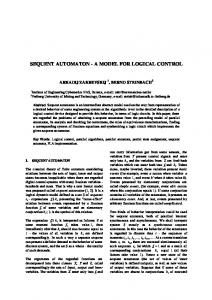
Fig. 3 Dissolution times of different grades of DF in the presence of %solutions of organic liquid (n = 5). Measurements for 0%-solvent were made using DI water. Unfilled circles / triangles represent the highest measured concentration where the valve ‘did not burst’ (defined as not bursting after more than 15 minutes). Detail of experimental protocol and structure, and expanded view of burst times for AR and Embroidery film, are available in ESI (Fig S2).
approach, this can be implemented by locating the CFs of several valves at the same height in a common reservoir where they can be wetted / dissolved by a common liquid. This parallel valve actuation can also be enabled by using a valve design where multiple fluidic elements (with individual LFs) share a single CF. Furthermore, by co-locating the dissolvable CF and LFs, a configuration which is topologically similar to the DF burst valves described previously 19 can be created. However, rather than increasing the spin rate to open the valve, in this approach the DF is dissolved from the ‘downstream’ side by the ancillary liquid, which subsequently mixes with the main liquid. Co-located CF / LF valves can be particularly useful when employed to open a fluidic path to preferentially divert liquid to distinct collection chambers. They can also be employed to restrain a liquid which is not capable of dissolving the DFs.
3. Materials and Methods 3.1 Disc Manufacture and Assembly
2.2 Network Configurations In addition to the basic configuration (Fig. 1a-c), the nature of valve actuation, which is akin to an electrical relay, lends itself to more sophisticated configurations. In the first case, by locating the CF of one valve such that it can be dissolved by liquid released by an earlier valve actuation, valves can be configured to open in a serial cascade. This sequential release configuration, continuing the analogy of electrical circuits, can be further expanded to provide logical flow control elements. An AND-condition is represented by a valve which opens only when two or more upstream valves have been actuated (Fig. 1d-f). This AND-condition can be implemented by positioning the CF in a reservoir where it can only be wetted by the presence of the aggregate volume of at least two ancillary liquids. Similarly, a valve geometry which uses a number of CFs with one LF, dissolving any of the CFs will prompt the release of the restrained liquid, thus providing an OR condition. Parallel actuation of two or more valves is also possible. In one
View Article Online
DOI: 10.1039/C4LC00380B
70
75
80
85
The microfluidic discs (Fig. 2) were assembled from four layers of Poly(methyl methacrylate) (PMMA) and four layers of pressure sensitive adhesive (PSA) (Adhesives Research, Limerick, Ireland) 31. Small features such as microchannels were created from voids cut in PSA (86 µm thick) using a knife-cutter (Graphtec, Yokohama, Japan). Larger features such as reservoirs were created from voids in the PMMA layers (1.5 mm thick) using a laser cutter (Epilog Zing, USA). Layer 1 (PMMA) consisted of loading vents. Layer 2 (PSA) consisted of top-level microchannels for liquid transport and pneumatic venting. Layer 3 (PMMA) provided large reservoirs and through-holes which act as vertical vias. Layer 4 (PSA) was a cover layer which sandwiches the DF tabs in place. Layer 5 (PSA) was a support layer for DF tabs and contained voids where the DF tabs could be positioned. Layer 6 (PMMA) contained the through-holes which acted as vertical vias. Layer 7 (PSA) features the lower-level microchannels which for guiding flow and pneumatic venting. Layer 8 (PMMA) acts as mechanical backing. The microchannels on Layers 2 and 7 are isolated from each other to allow channels crossing. The discs
Lab on a Chip Accepted Manuscript
Published on 25 April 2014. Downloaded by Dublin City University on 30/04/2014 18:33:03.
Lab on a Chip
5
10
Lab on a Chip
Fig. 4 Network of 10 valves (a) schematic of the disc structure displaying the location of DFs and linking channels on the lower level of the disc structure. Note also that, for clarity, the components DFs of valves are labelled rather than the valves themselves (e.g. Valve #1 is constituted of CF#1 and LF#1). (b) disc with all reservoirs loaded and the liquid subjected to high centrifugal field (60 Hz) (c) plot showing the disc spin-rate protocol and timing of valve actuations (n=3). Two DF grades were tested (KC-film and Embroidery (E)-Film). Opening of control films is shown by red diamond symbols while load films are shown by green circles. The blue dashed line shows the network dependencies between each valve. Parallel actuation (CF3/5 and LF7), ANDcondition triggering (CF6), valving the same liquid element twice (V6 and V10) and fluid mixing (CF/LF9) are shown. Time variation/error for each actuation step was less than ±1.2s and for clarity error bars have been disregarded. A panel by panel version of this figure is available in ESI. Movies (1 and 2) are also available.
used for total RNA extraction were manufactured using the anticontamination protocol described by Dimov et al. 30. Further detail is available in ESI. 3.2 Dissolvable Film Tabs
15
20
25
30
35
40
View Article Online
DOI: 10.1039/C4LC00380B
As the dissolvable films are non-adhesive, they were attached to double-sided pressure sensitive adhesive (PSA) to create sticky tabs19. Two tab geometries were used, circular for LF and slotshaped for CFs. It was found that, if the ancillary liquid filled the reservoirs before the CF could be dissolved fully, the ancillary liquid created an airlock and prevented the pneumatic chambers venting. The slot-shaped CF tabs provide increased tolerance to allow CFs to reside at the air / liquid interface; rather than submerged and air-locked by the ancillary liquid. Four different grades of DFs were used throughout this work. These were proprietary films provided by Adhesives Research (Adhesives Research, Limerick, Ireland) and referred to here-in as AR film 19, FA-35 film and KC-35 film (Harke Packpro, Germany) (referred to as FA and KC film, respectively) and a lowcost DF typically used for embroidery (Barnyarns, Ripon, UK; Avalon) and referred to here-in as Embroidery Film. While their compositions are proprietary, we used AR-films which are derived from an aqueous polymer matrix consisting of a range of constituents such as various cellulose derivatives, hydrocolloids acrylate copolymers, gums, polysaccharides and plasticizers 19. The KC and FA grades of the DFs are made from SOLUBLON®, a water-soluble film based on the synthesis of polyvinyl alcohol (PVA). The embroidery film is also mainly composed of PVA. Each grade of DF had different dissolution times in the presence of DI water (Fig. 3) and additionally in various concentrations of the organic fluids Isopropyl Alcohol (IPA) and Ethanol (EtOH). At some concentrations of organic solvent, the films would not dissolve (defined as > 15 minutes). All four grades of film had their dissolution times characterised using a microfluidic test
structure / experimental procedure (see ESI for further details). 3.3 Experimental Test Stand 45
50
55
60
65
70
The discs were characterized on an experimental “spin stand” 32 which has been described previously 33. Briefly, the discs were spun on a computer controlled spindle motor (Faulhaber Minimotor SA, Switzerland). A stroboscopic light source (Drelloscop 3244, Drello, Germany) and a sensitive, short-exposure time camera (Pixelfly, PCO, Germany) and the motor are synchronized using custom electronics visualize the hydrodynamics on the rotating discs. Aside from where otherwise specified, all discs are tested at 30 Hz rate of rotation. The discs are accelerated and slowed down at 12.5 Hz s-1. Further detail is available in ESI. 3.4 Cell Culture and Sample Preparation Cells were cultured, harvested and homogenate was prepared according to the protocol described previously 30. MCF7 cells (DSMZ, Braunschweig, Germany) were used in this study and were collected between their 17th and 25th passage. Cells were lysed on bench according to the standard protocol for phenolchloroform three phase extraction 29 by mixing a 25-μL aliquot of harvested cells in culture media (DMEM, FBS, penicillin and streptomycin) with 80 μL TRI Reagent® BD (Molecular Research Center Inc.), a reagent for performing three phase extraction 29. The aliquots contained 9.3 104 cells (enumerated using an automated counter (Scepter Handheld, Millipore, US) and in a haemocytometer counting chamber (Marienfeld, Germany) with a depth of 0.1 mm. The extracted aqueous phase (40 μL) containing the RNA was isolated through centrifugation and then mixed with 50 μL of RNAase-free water. These samples were then either processed on-disc or purified on bench using an IPA / EtOH precipitation protocol 30, 34. This protocol is detailed in the ESI.
Lab on a Chip Accepted Manuscript
Published on 25 April 2014. Downloaded by Dublin City University on 30/04/2014 18:33:03.
Page 5 of 10
5
10
40
4.1 Sequential Valve Actuation
20
25
Page 6 of 10
Fig. 5 Metering and Routing. This disc architecture demonstrates how event triggered valves can be applied to a typical biomedical assay which utilises sequential liquid handling steps (such as silica-based nucleic acid extraction or ELISA). Here dyed water substitutes sample, wash buffer and elution buffer. (a) Schematic of the disc including linking channels on the lower levels of the design. Note, for the sake of clarity, only the CF and LF valves are labelled (e.g. Valve#1 (V#1) is composed of CF#1 and LF#1) (b) shape of the structure (c-j) disc-based processing of the liquid. The experiment is initiated by accelerating the disc to 30 Hz and this spin rate is maintained throughout the experiment. The sample is metered and directed to waste through the reaction chamber. The wash buffer is then routed through the reaction chamber to the waste chamber. Finally, the elution buffer is guided through the reaction chamber to the sample recovery chamber. Note that in (d) the excess sample triggers the metering valve (V#1) and routing is achieved (h) by opening the co-located valve V#4 to open a passage for the sample to preferentially flow to the sample recovery chamber. Note also a residual amount of wash buffer (which was trapped in the reaction chamber) was directed to the sample recovery chamber when CF / LF#4 dissolved. While the preferential routing is based primarily on flow resistances, in some cases gas pockets trapped in downstream channels can increase the routing efficiency. ESI available (Movie 3 and Movie 4)
4. Integrated Fluidic Networks
15
View Article Online
DOI: 10.1039/C4LC00380B
The most basic network configuration is the successive actuation of serially concatenated valves. As described previously, a given valve is opened by the liquid released by an upstream valve, thus cascading the entire sequence. To demonstrate sequential release and more advanced network capabilities, such as parallel actuation and AND-condition triggering, a microfluidic disc with 10 event-triggered valves is presented (Fig. 4). This disc is preloaded with dyed water and, before the addition of an ancillary liquid, is accelerated to 60 Hz and the valves will not actuate (Fig. 4b). Stopping the disc, adding liquid to wet CF1, and accelerating the disc to 30 Hz initiates the cascade of 10 valves. The first two valves illustrate simple, sequential release concatenated valves. The wetting and dissolution of CF1 by the ancillary liquid triggers the release of liquid by V1, which then wets CF2 and opens V2.
30
4.2 Parallel and Conditional Valve Actuation
35
Following from this, the release of liquid from V2, in turn, wets CF3/5. These valves are configured in a geometry which enables parallel release. In this approach V3 and V5 are connected and share a single CF. Thus, dissolving CF3/5 vents the pneumatic chamber and triggers V3 and V5 in parallel. This logical relationship is shown by dashed blue lines in Figure 4c. Note also these valves must be loaded with similar volumes (to approximately balance centrifugally induced hydrostatic pressure). V6 illustrates an AND-condition valve. In this case, CF6 is lo-
45
50
55
60
cated such that only the aggregate fluid released by V4 and V5 is sufficient to contact, wet and dissolve CF6. Again, this logical relationship is shown by the dashed blue lines in Fig. 4c. Also note that the liquid released by V6 is transiently restrained by V10. V8 and V10 illustrate an alternative method of parallel valve actuation. In this case, the valves are completely separate (and thus can be loaded at separate times with different volumes) but their CFs are located within the same reservoir, and will therefore be wetted simultaneously. As these valves are triggered by liquid released through LF7, the parallel release is indicated by two dashed blue lines emanating from the LF7 symbol on the network diagram (Fig. 4c). V9 is a co-located valve which is topologically identical to the rotationally controlled (burst type) DF valves previously described 19. In this case, the dissolution of CF / LF9 by liquid released through V8 releases the liquid restrained by V9 and thus the two liquids mix. Note also that this structure was tested with two different grades of DF material (KC- and embroidery film) exhibiting significantly deviating dissolution times (Fig. 3). Consequently, while identical in their network configuration, the time to complete the 10 LUOs extends by a factor of three on a disc incorporating KC compared to E-films. 4.3 Liquid Metering and Routing
65
The conditional valving scheme demonstrated here may also enable the operations used in typical bioanalytical protocols. In the disc in Fig. 5, automatic metering, release of a wash reagent and selective routing of wash reagents and elution buffers to
Lab on a Chip Accepted Manuscript
Published on 25 April 2014. Downloaded by Dublin City University on 30/04/2014 18:33:03.
Lab on a Chip
5
10
15
20
25
30
35
40
45
Lab on a Chip
View Article Online
DOI: 10.1039/C4LC00380B
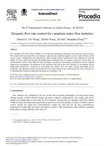
Fig. 6 Total RNA extraction using event-triggered valves (a) Architecture of Disc for Total RNA extraction. This disc demonstrates AND-condition triggering and selective fluid routing using biological samples and organic fluids. E-film was used for CF/LF4 while FA-film was used elsewhere throughout the disc for dyed water testing (see ESI). For Total RNA extraction AR-film was used for LF1, CF2, LF2 and CF3. (b) Image showing disc with Elution Buffer, EtOH Washes and Cell Homogenate loaded. (c) Solid-phase extraction of total RNA on-disc versus bench top precipitation protocol using IPA / EtOH by Chomczynski and Sacchi 29. Microchannel electrophoresis (Agilent Bioanalyzer 2100) shows that bench top (BT), extracted RNA has degraded while its on-disc counterparts with 5 min initial incubation (Inc., blue) or direct flow through (Dir., purple) have stayed intact. The RNA recovered after incubation (104.0 ng) is higher than the direct flow through the beads (59.5 ng); the highest is the amount of RNA recovered after BT (359.7 ng), however, some of it appears to be significantly degraded (as indicated by the pronounced small-RNA peak). Additional information is available in ESI. Movies of cartridge with both dyed water and biological samples are available in ESI (Movie 5, 6 and 7).
different collection chambers is demonstrated. Initially, a metering structure 18-19 provides a defined sample volume while the resulting overflow adopts the role of the trigger V1. This metered liquid is then routed through a reaction chamber and into a waste chamber (Fig. 5e) where, through wetting CF2, a wash liquid is released (Fig. 5f-g). This liquid is also routed through the reaction chamber and into the waste chamber. The aggregate liquid volume in the waste chamber liquid can now wet CF3, meeting an AND-condition and releasing a small volume of ancillary liquid (Fig. 5h). This liquid wets and dissolves a co-located valve (CF / LF4), which opens a fluid route between the reaction chamber and sample recovery chamber. The ancillary liquid continues to the sample recovery chamber where CF5 is wetted; triggering the release of an elution buffer (Fig. 5i). As a channel is now open between the reaction chamber and the sample collection chamber, the elution buffer is preferentially routed, due to the relative microchannel flow resistances, to the sample collection chamber (rather than the waste chamber).
50
55
60
5. Total RNA Extraction
65
4.4 Evaluation of Networks These disc cartridges demonstrate actuation of these valves in a number of different conditional states. Along with sequential actuation, the triggering of two valves in parallel (using two different methods) (Fig. 4) and metering (Fig. 5) were successfully demonstrated. These methods could, for example, be combined and extended to implement sample discretisation, metering and aliquoting 22 in applications such as multiplex genotyping. The use of these valves to actuate, through liquid transfer, the release of sequential reagents in a manner suitable for use with sample-wash-elute biomedical assays has also been shown (Fig. 5). Of particular importance is the capability to selectively route liquid to an alternative reservoir suitable for recovery or further processing. This application potential is confirmed using a co-located CF / LF valve. It should be noted that this disc design was tested repeatedly (n = 3) and in each case functioned as expected / described here with high reliability. Compared with other valving methods, they are particularly robust and even well compatible with low-fidelity prototyping methods. Yet, it should be noted that in order to
ensure proper operation, the valves possess a relatively large dead volume compared to most other centrifugal valving technologies. Additionally it should be noted that, as indicated by the scaling in Fig. 5c, the time for the completion of a liquid handling protocol depends on the dissolution time of the DFs. This structure was tested with Embroidery film and KC-35 film and it was found that each step was highly repeatable (±1.2 s variation in film dissolution time). However, the KC-35 film possesses a longer dissolution time than the E-films and thus the disc (Fig. 5) using KC-35 film took over 3-times longer to process than the disc manufactured using Embroidery film.
70
In order to demonstrate the applicability of these valves to a complex sample preparation protocol of high relevance to nucleic acid testing, the design introduced in Fig. 5 was adapted for the extraction of total RNA 29 comprising of sequential washes of retained glass beads (as a solid phase) with cell homogenate, IPA, EtOH and DI water. The primary modifications to the design shown in Figure 5 were to remove the metering structure (due to on-disc space considerations) and to introduce a second wash step (Fig. 6a). The disc was used to demonstrate extraction of total RNA at two conditions; where the sample is loaded and processed directly and where the sample is loaded and allowed to incubate on disc prior to processing. 5.1 Liquid Handling Protocol And Disc Design
75
80
85
The standard liquid handling protocol to complete this extraction encompassed 1) routing cell homogenate through acid-washed glass beads to waste, 2) release of Wash#1 (100% IPA) and routing through beads to waste, 3) release of Wash #3 (75% EtOH) and routing through beads to waste, 4) release of elution buffer (DI water) and routing through beads to the eluate chamber. However, no available DF film would dissolve in the presence of 100% IPA. The AR-film would dissolve in the presence of solutions of 90% IPA but, when the disc was stopped to load cellhomogenate, this liquid wicked into the valve pneumatic chambers and dissolved the LF and CF films. Therefore, the extraction protocol was modified to use two washes of 75% EtOH
Lab on a Chip Accepted Manuscript
Published on 25 April 2014. Downloaded by Dublin City University on 30/04/2014 18:33:03.
Page 7 of 10
5
Published on 25 April 2014. Downloaded by Dublin City University on 30/04/2014 18:33:03.
10
15
20
25
30
35
40
45
50
in lieu of 100% IPA followed by 75% EtOH. In the actual implementation, the EtOH washes resolved into a single, extended wash due to the short dissolution times of the DFs compatible with 75% EtOH (AR-film). The selective routing of cell homogenate and wash liquids to a waste chamber, while diverting the elution buffer (liquid carrying purified RNA) to a collection chamber, constitutes the primary microfluidic challenge for this protocol. RNA extraction has been implemented in centrifugal systems previously 30, 35. However, while the capability to automate the release of wash buffers 35 has been established, as has the capability to selectively isolate the elution buffer 30, to the authors’ knowledge this is the first time that both steps are implemented without requiring complex support instrumentation or stopping of a disc. The routing is enabled initially through an open microchannel leading from the sample chamber to the waste chamber (Fig. 6a). The microchannel has been extended by a serpentine to meet two design goals. In the initial phase, the flow resistance is enhanced compared to the channels leading from the wash reservoirs to the sample chamber, leading to accumulation of liquid within the chamber while the wash reservoirs are emptying. Secondly, as these valves are based on sacrificial technology, and cannot be closed, the long flow length means that, later in the protocol, the majority of elution buffer will preferentially divert down a channel of lower flow resistance. The cascaded sequential release of the wash buffers is implemented by means of an AND relationship; established by a series of staggered overflow structures where additional volume entering the waste chamber actuates the next valve in the sequence. The channel from the sample chamber to the RNA collection chamber is sealed using a co-located CF / LF valve. As this is opened before the elution buffer is released, a low flow-resistance route is created between these chambers. Additionally, as this valve can have a small pneumatic chamber, ingress of organic solvent into this valve during bead washing is minimised, thus reducing contamination of the elution buffer. The co-located CF / LF valve is opened through an ancillary liquid which is released by the addition of Wash #2 to the liquid volume in waste chamber. This ancillary liquid serves two functions; it first opens the co-located CF / LF valve and then, flowing into the RNA recovery chamber, triggers the release of the elution buffer. Note that this ancillary liquid (DI water in this case) could be substituted for any aqueous buffer (for example reagents for a reverse transcriptase step). The microchannel which leads from the extraction chamber to the RNA recovery chamber, while having a lower flow resistance than the channel leading to the waste chamber, still provides a greater flow resistance than the channel leading from the elution buffer reservoir to the extraction chamber. This again results in a build-up of liquid within the sample chamber before it drains into the RNA recovery chamber.
60
65
70
75
55
Page 8 of 10
larger beads combined with granular jamming (a.k.a. stonewall effect) tends to retain the beads in the sample chamber. Wash Chamber #1 and Wash Chamber #2 are both loaded with 90 µl of 75% EtOH / DI water. The ancillary and elution buffer chambers are then loaded with 20 µl and 90 µl of DI water, respectively. With these chambers loaded, the integrity of the valves was tested by rotating the disc at 60 Hz for a short period of time. The experiment is initiated by loading a 90 µl volume of cell homogenate (prepared off-chip as previously described from 40 µl recovered aqueous phase sample diluted with 50 µl of RNAasefree water). The disc was briefly spun at low frequency so the homogenate could contact the beads. In one case, the disc was stopped and the fluid was left to incubate for 5 minutes. The disc was then then accelerated and kept at 30 Hz for the duration of the experiment. In the other case, the disc was accelerated to 30 Hz directly from the loading step. At this point the entire sequence occurs automatically (over the course of approximately 6 minutes) without further operator intervention until, after the sequence is complete, the disc is stopped and the purified RNA sample is removed. 5.3 RNA Extraction Disc Results and Evaluation
80
85
90
95
100
105
5.2 Experimental Protocol Prior to placing the disc on the experimental spin stand, the sample chamber is loaded with 30 mg of acid-washed, dried glass beads (< 106 µm diameter). While some of the glass beads have a diameter smaller than the height of the outlet channel (defined by PSA with a cross section of 500 µm 86 µm), the presence of
View Article Online
DOI: 10.1039/C4LC00380B
110
115
Upon completion of the event-triggered sequence, the entire elution buffer RNA (~100 μL (90 μL elution buffer plus 20 μL ancillary liquid minus losses)) was recovered from the disc and the total RNA content was measured using quantitative microchannel electrophoresis (Fig. 6c). An identical control sample was processed on bench and was analysed using the same system (359.7 ng measured, Fig. 6c). The sample, which was incubated on-disc for 5-minutes (Fig. 6c), yielded a concentration of 1.04 ng μL-1 (a mass of 104 ng of total RNA was measured in the eluate) corresponding to 28.9% extraction efficiency compared to bench-top. The flow-through sample yielded 59.5 ng total RNA (0.595 ng / μL in 100 μL or 16.6% efficiency compared to benchtop). Figure 9c shows that the bench-top control samples had traces of degradation (the baseline is shifted upwards and the peaks are broad). In comparison, the samples processed on-disc display the horizontal base-line and well-defined peaks associated with good quality, intact RNA. While this analysis method does not conclusively prove the biological usability of the sample (as, for example, a follow-on RT-PCR step would) it strongly indicates, as a proof-of-concept, the potential use of these valves for this application. This disc cartridge was also tested with aqueous solutions for visualisation purposes (see ESI). In that case, the disc cartridge functioned reliably and repeatedly. However, for total RNA extraction, the incompatibility of the DFs with certain concentrations of DI water / organic solvent solutions required some design compromises, and confined the performance when applied to total RNA extraction (i.e. washing beads with 75% EtOH rather than 100% IPA followed by 75% EtOH). Similarly, the long drying times used in the protocol previously described 30 were not available due to the automatic manner in which the valves actuate. Despite these variations from the optimal protocol, the extraction proved to be effective. Additionally, this structure also worked well with just aqueous solutions (dyed water, see ESI movies). This is particularly promising as aqueous solutions are widely
Lab on a Chip Accepted Manuscript
Lab on a Chip
Lab on a Chip
References
used in bioanalytical assays.
6. Conclusions and Outlook
Published on 25 April 2014. Downloaded by Dublin City University on 30/04/2014 18:33:03.
5
10
15
20
25
30
35
For the first time an event-triggered flow control mechanism for large-scale integration of microfluidic flow control is presented. By demonstrating the coordination of 10 flow control operations using Boolean-like conditional relationships, it is shown that these valves can significantly extend the scope of process automation and parallelization on centrifugal microfluidic lab-on-adisc platforms. Additionally, these valves enable LUOs such as metering and selective routing of flow. Finally, as a proof of concept, a disc cartridge has been developed to extract total RNA from cell homogenate; showcasing the practical application of logical AND-condition liquid release and the selective routing of liquid using co-located CF / LF valves. In comparison to active valves, the event-triggered valves presented here require only a low-cost spindle motor. Unlike conventional rotationally actuated valves, the event-triggered valves function largely independent of the disc spin rate. Using these valves, the control of valve actuation is, rather than being a function of a pre-defined disc spin profile, transferred to and governed by the disc architecture. The sequence of valve openings is governed by the layout of the disc while the timing of valve actuation is automatically controlled by the interval required for liquid to move about the disc and to dissolve the DFs. This technology enables implementation of spin rate dependent LUOs, such as “shake-mode” Euler mixing, without the need to limitation imposed by valve burst frequencies. The decoupling of valve actuation from the spin rate also significantly expands the number of process steps that can be integrated on a disc, as it is now largely only confined by the available real estate of the microfluidic (disc) substrate rather than available burst frequencies. Furthermore, as these valves are independent of disc spin rate, they offer the potential to be generalised to (noncentrifugal) pressure-driven lab-on-a-chip systems.
55
60
65
70
75
80
85
90
95
Acknowledgements
40
The authors would like to acknowledge and thank Olivier Faneuil and Abhishek Vembadi for their assistance manufacturing and testing the microfluidic cartridges used in this paper. This work was supported by Enterprise Ireland under Grant No CF/2011/1317, the ERDF, and the Science Foundation Ireland under Grant No 10/CE/B1821.
100
105
Notes 110
45
50
*To whom correspondence should be addressed:
[email protected];
[email protected] a Biomedical Diagnostics Institute; Dublin City University; Glasnevin; Dublin 9; Ireland b School of Physical Sciences; Dublin City University; Glasnevin; Dublin 9; Ireland c Current affiliation: Dept. of Biochemical Engineering; University College London, United Kingdom ESI is available
View Article Online
DOI: 10.1039/C4LC00380B
115
120
1. J. Ducrée, S. Haeberle, S. Lutz, S. Pausch, F. von Stetten, R. Zengerle, J Micromech Microeng, 2007, 17, S103-S115 (DOI: 10.1088/0960-1317/17/7/S07) 2. M. Madou, J. Zoval, G. Jia, H. Kido, J. Kim, N. Kim, Annu. Rev. Biomed. Eng., 2007, 8, 601-628 (DOI: 10.1146/annurev.bioeng.8.061505.095758). 3. R. Gorkin, J. Park, J. Siegrist, M. Amasia, B.S. Lee et al., Lab on a Chip, 2010, 10(14): 1758-1773 (DOI: 10.1039/B924109D ). 4. C.E. Nwankire, G. Donohoe, X. Zhang, J. Siegrist, M. Somers et al., Analytica Chimica Acta 2013, 781: 54-62 (DOI: 10.1007/s10404013-1266-x) 5. M.C.R. Kong, E.D. Salin, Anal. Chem 2012 84(22): 10038–10043 (DOI: 10.1021/ac302507t) 6. H. Hwang, Y. Kim, J. Cho, J. Lee, M.S. Choi et al. (2013) Anal. Chem 85(5): 2954-2960 (DOI: 10.1021/ac3036734) 7. J.W. Hurst, J.W. Mortimer, Laboratory Robotics, a Guide to Planning, Programming and Applications VCH Publishers Inc, 1987. 8. P. Zucchelli, B. van de Vyver, Patent document WO200405024, 2004. 9. J.L. Garcia-Cordero, D. Kurzbuch, F. Benito-Lopez, D. Diamond, L.P. Lee et al., Lab on a Chip, 2010, 10(20): 2680-2687 (DOI: 10.1039/c004980h) 10. B.S. Lee, Y.U. Lee, H.S. Kim, T.H. Kim, J. Park et al., Lab Chip, 2011, 11(1): 70-78 (doi: 10.1039/c0lc00205d) 11. K. Abi-Samra, R. Hanson, M. Madou, R. Gorkin, Lab Chip, 2011, 11(4): 723-726 (doi: 10.1039/c0lc00160k). 12. W. Al-Faqheri, F. Ibrahim, T. Hwai, G. Thio, J. Moebius et al., PLOS ONE 2013, 8(3): e58523 ( doi: 10.1371/journal.pone.0058523). 13. T. Kawai, N. Naruishi, H. Nagai, Y. Tanaka, Y. Hagihara et al., Anal. Chem, 2013, 85(14): 6587–6592 ( doi: 10.1021/ac400667e) 14. J. Chen, P. Huang, M. Lin Microfluidics Nanofluidics, 2008, 4(5): 427-437 (DOI: 10.1007/s10404-007-0196-x) 15. J.L. Moore, A. McCuiston, I. Mittendorf, R. Ottway, R.D. Johnson, Microfluidics and Nanofluidics, 2011, 10(4): 877-888 (DOI: 10.1007/s10404-010-0721-1). 16 T. Hwai, G. Thio, S. Soroori, F. Ibrahim, W. Al-Faqheri et al., Med Biol Eng Comput, 2013, 51(5): 525-535 (DOI: 10.1007/s11517-0121020-7) 17. T. Li, L. Zhang, K.M. Leung, J. Yang, J Micromech Microeng, 2010, 20 (10): 105024 (doi:10.1088/0960-1317/20/10/105024). 18. S. Haeberle, T. Brenner, R. Zengerle, J. Ducrée Lab Chip, 2006, 6(6): 776-781 (DOI: 10.1039/B604145K). 19. R. Gorkin, C.E. Nwankire, J. Gaughran, X. Zhang, G. Donohoe et al., Lab Chip, 2012, 12(16): 2894-2902 (DOI: 10.1039/C2LC20973J ). 20. T. van Oordt, Y. Barb, J. Smetana, R. Zengerle, F. von Stetten, Lab Chip 2013, 13 (15): 2888-2892 (DOI: 10.1039/C3LC50404B). 21. H. Hwang, H.H. Kim, Y.K. Cho, Lab Chip, 2011, 11 (8): 1434-1436 (DOI: 10.1039/C0LC00658K ). 22. D. Mark, P. Weber, S. Lutz, M. Focke, R. Zengerle et al., Microfluidics Nanofluidics 2011, 10(6): 1279-1288 (DOI: 10.1007/s10404-010-0759-0). 23. J. Siegrist, R. Gorkin, L. Clime, E. Roy, R. Peytavi et al., Microfluidics Nanofluidics 2009, 9(1): 55-63 (DOI: 10.1007/s10404009-0523-5) 24. M. Kitsara, C.E. Nwankire, L. Walsh, G. Hughes, M. Somers et al. Microfluidics Nanofluidics,2013, (DOI: 10.1007/s10404-013-1266-x) 25. R. Gorkin, C. Liviu, M. Marc, H. Kido, Microfluidics Nanofluidics 2010, 9(2): 541-549 (DOI: 10.1007/s10404-010-0571x). 26. N. Godino, R. Gorkin, A.V. Linares, R. Burger, J. Ducrée Lab on a Chip, 2013, 13(4): 685-694 (DOI: 10.1039/C2LC40722A). 27. C.E. Nwankire, D.S.S Chan, J. Gaughran, R. Gorkin et al. Sensors 2013, 13(9): 11336-11349 (doi:10.3390/s130911336). 28. Y. Ukita, M Ishizawa, Y. Takamura, Y. Utsumi in Proceedings of µTAS2012, Okinawa, Japan, 2012. 29. Chomczynski P, Sacchi N, Anal. Biochemistry, 1987, 162(1): 156-159 (DOI: 10.1016/0003-2697(87)90021-2).
Lab on a Chip Accepted Manuscript
Page 9 of 10
Lab on a Chip
Published on 25 April 2014. Downloaded by Dublin City University on 30/04/2014 18:33:03.
10
15
Page 10 of 10
30. N. Dimov, J. Gaughran, E. Clancy, T. Barry, T.S. Smith et al. In Proceedings of Transducers2013, Barcelona, Spain, 2013 (DOI: 10.1109/Transducers.2013.6627325). 31. D.A. Bartholomeusz, R.W. Boutté, J.D. Andrade, Microelectromechanical Systems 2005, 14(6): 1364-1374 (DOI: 10.1109/JMEMS.2005.859087). 32. M. Grumann, T. Brenner, C. Beer, R. Zengerle, J. Ducrée, Review of Scientific Instruments, 2005, 76(2):025101 (10.1063/1.1834703). 33. D. Kirby, J. Siegrist, G. Kijanka, L. Zavattoni, O. Sheils et al., Microfluidics Nanofluidics, 2012, 13(6): 899-908 (DOI: 10.1007/s10404012-1007-6) 34. R. Boom, C.J. Sol, M.M Salimans, C.L. Jansen, P.M. Wertheim-van Dillen et al., J. Clin. Microbiol.,1990, 28(3): 495–503 35. B.H. Park, J.H. Jung, H. Zhang, N.Y. Lee, T.S. Seo, Lab Chip, 2012, 12(20): 3875-3881 (DOI: DOI: 10.1039/C2LC40487G ).
Lab on a Chip Accepted Manuscript
5
View Article Online
DOI: 10.1039/C4LC00380B