which includes sensor code and smartphone app development. Two types of .... this issue, Android uses sandboxing to secure direct data access between apps.
Evidence-based Development Approach for Safe, Sustainable and Secure Mobile Medical App Priyanka Bagade, Ayan Banerjee and Sandeep K. S. Gupta Arizona State University {pbagade, abanerj3, sandeep.gupta}@asu.edu
Summary. According to industry surveys, by 2018, more than 1.7 billion smartphone and tablet users will have downloaded at least one mobile medical app (MMA) [40]. Such widespread adoption of smartphone based medical apps is opening new avenues for innovation, bringing MMAs to the forefront of low cost healthcare delivery. These apps often control human physiology and work on sensitive health data, thus it is necessary to have evidences of their trustworthiness before actual marketing. The key challenges in ensuring trustworthiness of MMAs are maintaining privacy of health data, long term operation of wearable sensors and ensuring no physical harm to the user. Traditionally, clinical studies are used to generate evidences of trustworthiness of medical systems. However, they can take a long time and could potentially harm the user during studies. Thus it is essential to establish trustworthiness of MMAs before their actual use. One way to generate such evidences can be using simulations and mathematical analysis. These methods involve estimating the MMA interactions with human physiology. However, the nonlinear nature of human physiology makes the estimation challenging. Thus, it is required to analyze and develop MMA software while taking into account its interactions with human physiology to assure trustworthiness. This chapter focuses emerging app development methodologies, which support automatic evaluation of trustworthiness of MMAs by supporting automatic generation of evidences. This methodology involves, a) evidence generation to assure trustworthiness i.e. safety, security and sustainability of MMAs and b) requirement assured code generation for vulnerable components of the MMA without hindering the app development process. These methods are intended to expedite the design to marketing process of MMAs. In this regard, this chapter discusses example models, tools and theory for evidence generation with the following themes: • • • •
Software design configuration estimation of MMAs: Using an optimization framework which can generate sustainable and safe sensor configurations while considering interactions of the MMA with the environment. Requirements verification of the MMA design: Using models and tools to verify safety properties of the MMA design which can ensure the verified design will not cause any harm to the human physiology. Automatic code generation for MMAs: Investigating methods for automatically generating safety, sustainability and security assured software for vulnerable components of a MMA. Performance analysis of MMA software developed using evidence-based approach: Evaluating quality and response time of MMA software developed using evidence-based approach .
1 Introduction Use of mobile medical apps (MMAs) in healthcare is becoming prevalent as they provide low cost healthcare delivery [40]. These apps often control human physiology by acting as a controller to wearable and implanted medical devices such as artificial pancreas which automatically controls the blood glucose level by infusing insulin. They also provide diagnosis using physiological data collected by implanted sensors. Such close interaction of MMAs with human physiology make them critical. Thus, despite their ability to provide low cost healthcare delivery, getting these apps in the market is a tedious process e.g. design for the automated artificial pancreas came in 1999s [28]. However the actual app is marketed in 2014, which is a first generation app and capable of only predicting hypoglycemia (low blood glucose level) [65]. Due to involvement of human physiology, MMAs are technically challenging to implement and get market approval which requires to establish trustworthiness of these apps. Trustworthiness of MMAs can be viewed as having properties such as interaction safety, communication and storage security and wearables sustainability [44]. Assuring these trustworthy properties in MMAs is challenging due to difficulty in extracting their interactions with human physiology, which leads to lack of mathematical structure to objectively provide evidences of the MMAs. The evidence can be defined as a set of observations on certain properties of
MMA software and its effects on the human body, generated through the usage of scientifically sound emulations, clinical studies, simulations and mathematical proofs. Traditionally, emulations and clinical studies are used to generate evidences of trustworthiness of MMAs. However they can be difficult and costly to be comprehensive due to the requirement of approval from institutional review board (IRB) and patient availability. These techniques can also potentially harm the user and may take long time to establish their trustworthiness. Simulation and mathematical proofs can generate evidences before the actual use of the MMAs on the user. However, developing such techniques might increase app development time and may require higher skills set from the developer. Thus, this chapter focuses on discussing, tools and techniques to enable evidence-based design and development of trustworthy MMAs without hindering the app development process. Simulating the MMA involves estimating its interactions with human physiology. It uses models of MMA software and human physiology to appraise the values of continuous variables of the system over certain time. These values are then used to estimate resource requirements, cost and verify the design against requirements which can provide evidence for the trustworthiness of a MMA design. The nonlinear and spatio-temporal nature of the human physiology makes its models difficult to simulate. Further, the events generated in controller software and human physiology changes the system configurations. Thus inaccurate handling of such events might end up in getting sub-optimal design. Accurate handling of the events require infinitely small time step in current simulators, which leads to increased simulation time. Thus to overcome these challenges in accurately simulating MMAs, the chapter gives an overview of an example simulator with a time refinement approach which predicts the event timing and accordingly modify the time step to handle the event. Formal methods, which provide mathematical proofs to show correctness of the software, can be used to obtain the evidence of the trustworthy properties of MMAs. Formal methods encompasses several techniques such as equivalence checking, symbolic execution, model checking, theorem proving etc. This chapter uses model checking approach for generating evidence of trustworthiness of MMAs. It uses a state based abstraction of the MMA software. The discrete states of the abstraction represent the operating conditions of the software, while the transitions in the state are governed by changes in the human physiology variables. An execution of this state based model results in valuations of the system variables. If the set of all possible valuations intersects with the unsafe set, then the system will not satisfy the trustworthy properties. This analysis is typically called reachability analysis. It requires solving non-linear, spatio-temporal differential equations of human physiology to accurately estimate values of system variables. The available solutions for reachability analysis are for linear systems. Thus they cannot be directly applicable to the human physiology based systems which are non-linear in nature. There has been many efforts to reachability analysis of nonlinear systems such as piecewise linearization [14, 15], polynomial approximation using Bezier curves [33] etc. This chapter discusses one of such technique to perform rechability analysis of nonlinear systems using exponential box splines, which are traditionally being used for curve fitting in geometric modeling. Simulations and mathematical proofs can be used to develop trustworthy MMAs as well as to generate evidences. The verified MMA design obtained using these techniques can be used to develop MMA using automated code generator to reduce manual implementation errors which is a main cause of software failures. Such automated techniques can be used, if the implementation follows a standard model. However, the standard model may lead to generate similar types of MMAs and might limit the functionalities of the smartphone that can be exploited by the developers e.g. different graphical user interfaces, data displaying techniques. Thus, to avoid such limitations, the app developer should be responsible for developing GUI and processing algorithms on smartphone end and the critical interfaces such as data communication, sensor/actuator code should be generated and handled by the trustworthy entity. Thus, the chapter hypothesizes that trustworthy mobile medical applications should have an operating model, where every instance of data communication to the sensor, data storage in the smartphone, control inputs to the actuator, interaction with the user, data communication to the Electronic Health Record (EHR) and even EHR access by physician has to pass through a certification entity, Trustworthy Data Manager (TDM). 1.1 Overview of the chapter To ensure the trustworthiness of MMAs, the MMA software development process should provide evidences at every step of its life cycle. Such evidence-based MMA development process (Figure 1) can be divided into four parts, a) Design, b) Verify if design meets requirements, c) MMA Implementation, and d) Verification and Validation of implemented MMA. The process starts with obtaining MMA design which should
Traditional MMA Development Techniques Manual Implementation
?
Manual Implementation MMA Implementation
Get MMA design (App and Sensors/Actuators) satisfying requirements of MMA
Evidence to Verify if Design meets requirements
Wearable Sensors & Actuators ECG EEG Accelerometer
Infusion Pump
App Implementation
Clinical Study Evidence to 1. Verify if Implementation meets the Design 2. Validate if Implementation meets the requirements
Proposed Tools and Theories to enable Evidence-based MMA Development 1. Sensor/Actuator Configuration Optimization Framework 2. Hybrid Simulator
Formal Methods characterizing interaction between human body and MMA software
Automatic Code Generation using standard MMA operating model
1. Comparison of generated code with already verified code 2. Emulation and clinical study
Fig. 1: Overview of evidence-based MMA development approach. satisfy trustworthy requirements of MMA. It is then followed by providing evidence to check if the obtained design meets the trustworthy requirements of MMAs. This verified design is then used for implementation which includes sensor code and smartphone app development. Two types of evidences are required for implemented code to verify if the implementation follows the design and to validate if the implementation ensures trustworthy requirements of MMAs. Traditional app development method uses only controller software simulator which does not estimate interactions with human physiology. Further, manual implementation method is used for MMA software development which it does not provide any evidence for correctness of the design. The implemented code is generally validated using experiments such as clinical study which is time consuming and might lead to user safety hazards due to wrong design or implementation. The chapter focuses on filling the gap by providing example models, tools and methodologies to generate evidences with theoretical guarantees for ensuring correct working of MMAs before their experimental studies. The research topics and their example solutions in MMA development process are discussed as follows: •
MMA Design: MMAs interact with environment through wearable devices, e.g. wearable devices scavenge energy from unpredictable sources such as human heat, sun light etc. Also as they are implanted on human body, they interact with human physiology by controlling it using actuators or by heating the human skin at the sensor worn spot. Thus to assure sustainable and safe working of the MMAs, the design of the wearable devices should consider the interaction effects [70]. Traditional MMA design techniques fail to consider these interactions, which might result in an unsafe and power hungry design. Thus, it is important to address following research question while configuring the wearable sensor/actuators in MMAs: How to incorporate interactions of MMA with its environment while configuring the sensor/actuator? Available Solutions: Typically optimization frameworks are used to obtain sensor configuration for given requirements. One of the example solution discussed in Section4 is the use of an optimization framework to get sensor configuration that supports privacy ensured continuous monitoring powered by energy scavenged from human body or sun light and does not cause any harm to the human physiology [17]. It takes hardware and software requirements of the sensor/actuator to generate the optimal design. The framework uses hybrid simulator to simulate human physiology and controller algorithm to obtain the safe design. Researchers have proposed many such hybrid simulators [11,39,42]. This chapter discusses
•
one example hybrid simulation method in Section 5 to accurately handle events from human physiology and controller algorithm to get realistic system behavior. Design Verification: This step acts as an evidence for the design obtained in previous step follows the requirements. The software design verification usually involves logical reasoning by giving a mathematical proof of correctness of the design. In case of MMAs, as they directly interact with human physiology, considering the effect of MMA operation on human physiology is the important part in the reasoning process. Traditional MMA development techniques do not provide any of such method for the reasoning. Thus, following research question needs to be answered: How to generate evidence for the MMA design using models of human physiology?
•
Available Solutions: Formal techniques can be used to perform MMA design verification. In the example technique incorporated in this chapter, the combined analysis of continuous dynamics of human physiology and discrete dynamics of the MMA controller software is done using reachability analysis. Reachability analysis computes the values of continuous variables of the system with a given controller at any point in time. These values are further used to check instability in controller design. There has been many methods proposed by researchers to do reachability analysis of non-linear systems such piece-wise linearization [14,15], polynomial approximation using Bezier curves [33]. One of such technique discussed in this chapter in Section 6 uses exponential box splines to represent the trajectory of these continuous variables of nonlinear systems. Exponential box splines are being traditionally used for curve fitting in geometric modeling. Their curve fitting property will be applied to express the nonlinear variation of the continuous variables in the system. MMA Implementation: Traditional app development process uses manual implementation which might result in software bugs. These errors can lead to safety and security issues such as bug in the infusion pump controller software can lead to excess drug infusion in the blood which can lead to distress, error in security algorithm can cause leakage of health data. In order to avoid these issues the app software should be bug-free. Thus, the chapter focuses on following research question: How to reduce manual implementation errors in MMAs?
•
Available Solutions: Automated code generation can be used to reduce manual implementation errors [23, 26, 57]. This chapter discusses the example of Health-Dev tool [23], a model based automatic code generator for sensors and smartphones. The chapter explains how Health-Dev tool can be extended to generate TDM with safe, secure and sustainable sensor and smartphone code. In the extended tool, customizable code for sensor communication, data storage in smartphone and communication to the EHR will be automatically generated from high level descriptions using a parameterized code frame data-base. The visualization software (Graphical User Interface) can be independently developed by a manufacturer. The extended Health-Dev tool, referred as Health-Dev β tool will be equipped with a database of security enabled communication protocol code frames such as password based and physiological value based security. Verification and Validation of implemented code: To check if the implemented code conforms to the requirements and design of the MMA, the use of clinical studies in traditional app development methods can be hazardous to human physiology. Thus, the implemented code can be compared with already verified code such as BSNBench [61] to verify if the implemented code satisfies the MMA design. Further, emulation platform can be used to validate the MMA requirements of safety from MMA operation before actual use of the app. Such emulation platform can use field-programmable analog arrays (FPAAs) to implement sensor design. The ability of FPAAs to emulate the operation of human physiology represented by differential equations enables them to test power consumption and adverse effects on human physiology.
2 Related Works Mobile medical apps (MMAs) are involved in critical healthcare operations which might lead to risks or hazards to human physiology. The risks addressed in this chapter are categorized as: a) safety violations, a user is not harmed due to the operation of the smartphone app (the controller app might harm user physiology), b) security violations, user’s data is always kept private and free from unauthorized access (unauthorized
access to the health data), and c) sustainability violations, lack of availability of apps due to resource constraints such as power, CPU, and memory. These are the trustworthy properties of MMAs which need to be evaluated before the actual use of the app to have dependable healthcare system.. Traditionally, static analysis, complexity analysis of the source code, functional testing, structural testing are used to check errors in the developed software [13, 36]. These techniques may not ensure that the program is totally bug-free as they check for particular types of errors or requirements only e.g. static analysis focuses on buffer overflows, null pointer detection, dead code detection but fail to consider the interactions of system with environment. Further, system monitoring approach is used to establish trust in software working which relies on specified operating conditions of the system and detects anomaly in system behavior such as component failure, memory corruption, change in environment [45]. However, the monitoring of the system can be used after the system deployment which can lead to testing certain requirements only and fixing any critical error might lead to redeveloping the product or dealing with potential harm to the software environment. Considering the critical nature of the MMAs, the trustworthiness should be established before the actual use of the system to ensure no harm to the user when being tested in clinical studies. To avoid, the software testing flaws after development, process based methods are used to establish software trustworthiness where the trustworthy properties of the software are tested at every step of the development life cycle [12, 59, 64]. They are mainly focused on converting the trustworthy requirements in finite state machines (FSM) and then testing the automata to check if the design satisfies the requirements as well as developed software functions according to the FSM. In case of MMAs, the interactions between discrete system i.e. MMA software and continuous system i.e. human physiology need to be studied to establish trustworthiness. However, FSM provides limited support to represent such hybrid system. Thus these methods cannot be used to verify the MMA design to check the trustworthy properties. There has been several frameworks proposed for developing MMAs to reduce development time. UPHIAC application [54] framework provides interfaces for networking, storage, measurement devices and user interface for data visualization. However, it does not include any discussion on how trustworthy properties of the MMA will be handled. It uses smartphone sensors only, not the external ones or use external proprietary sensors which may not support any modifications in parameter configurations. Further, secure data communication, sharing data with other apps, storage in cloud is one of the main concerns in MMAs. Researchers have extensively addressed the issue of data sharing in mobile apps and cloud while considering the pervasive monitoring systems [8, 27, 43, 60]. Open mHealth architecture [38] promotes the use of having single framework which can collect data from various apps used by the patient/user and share with the physician instead of asking each app to upload data separately. It mainly focuses on data transfer from apps to cloud. However it does not check for security vulnerabilities during the data transfer. bHealthy [60] promotes the use of data sharing between apps to give better feedback to the user. Mobius [27], a middleware for interfacing with complex data management, supports unified data messaging and abstraction for mobile apps. Another interface (Simba) [8] interfaces the complexities of synchronizing data to the cloud with minimal work from the developer. A Service-Oriented Context-Aware Middleware (SOCAM) has been proposed [43] to enable rapid prototyping of context-aware services in pervasive computing environments. SOCAM provides a middleware of components to define context providers, interpreters, and the interaction between different components. All of these approaches use APIs to provide the interfaces and require an app to change structural design to adapt to the interface. Configuration of the APIs is tedious and inaccuracy in setting the API parameters correctly can result in failure of the system. Thus, to reduce development effort a non-invasive interface provider framework is needed which requires very less configuration. In this regard, TDM app can be used to provide critical interfaces for MMAs. It allows developer to use the interfaces in the same way as communicating with other app on the smartphone and avoids possible configuration issues. Several individual efforts are taken to assure trustworthy properties in MMAs. The safety violation of the apps can be caused by compromising health data by sharing it with non-legitimate app. To combat this issue, Android uses sandboxing to secure direct data access between apps. Inaccurate control input to actuator computed by MMA can cause serious harm to human physiology. This issue can be viewed as verification hybrid model and existing techniques such as reachability analysis can be used to verify the control algorithm before implementation [16, 18]. Further, there has been many efforts taken to secure data communication over wireless channel for in body implanted sensors and smartphone [20, 41, 48, 49, 73]. The availability of the sensors can be jeopardized by low battery capacity. This issue is mainly addressed by using schemes such as throttling, duty cycling, sustainable sensing [66]. All these efforts to combat safety, security and sustainability issues focus independently on each issue and try to find solution for it. However in case of MMAs, a technique is needed which should consider the inter-effect of these issues on each other.
This creates a need to have a MMA development framework which can ensure trustworthy properties while generating the evidences at every step of the development process. This leads to develop a framework which can specifically focus on trustworthy properties in MMAs.
3 Mobile Medical Apps Examples MMAs communicate with physiological sensors worn by the user and use the collected physiological data for further processing such as diagnosis, controlling actuator operation, displaying data in user readable format. The apps also communicate with a cloud server to upload the health data to an electronic health record (EHR) which is a health data storage. Since, MMAs control medical grade actuators and monitor health, they need to meet safety, security and sustainability requirements. Indeed, Food and Drug’s Administration (FDA) classify smartphone health apps as medical devices. According to the definition of the MMAs published by FDA in September 2012, the healthcare apps can be classified in three types, a) displaying app - which displays the sensor data in graphical format, b) diagnostic app - which processes the collected physiological data and provides diagnostic feedback to the user, and c) controlling app which controls the actions of the body implanted actuator device depending the sensed physiological signals. Following MMA examples are used throughout the chapter to explain the example solutions. The example MMAs are classified according to the FDA definition of smartphone medical apps. Example 1 PETPeeves: Display app: PETPeeves is an app aimed to help users alter their lifestyle to be healthier by presenting the user with a virtual pet whose mood changes based on the amount of exercise the user performs a week. The app uses accelerometer and ECG sensor to monitor the user’s heart rate and accordingly calculates calories burned during exercise. Example 2 BrainHealth: Diagnostic app: The app consists of three activities-focus, mood change, and relaxation. Focus is aimed towards users who suffer from learning disabilities and need a boost in mental performance, motivation, and focus. Mood change is aimed towards users whom are not satisfied with their mood and want to achieve a more positive mood. Lastly, relaxation is aimed at any user who wants to learn how to relax in any situation. The app consists of a visual feedback system which uses a glob of goop. When the user is performing well in an activity, the glob is very structured and dense, however when the user’s performance degrades, the glob breaks apart and the goop drifts to the edges of the screen. Neurofeedback or phsychostimulants are found to be an effective method for encouraging healthy behavior [69]. PETPeeves app uses this neurofeedback as additional input to give reward points to the user which acts as the bonus to pet’s mood modifier. Example 3 Artificial Pancreas/Infusion Pump App: Controller App Automated control of blood glucose levels in human are often obtained using artificial pancreas. Artificial pancreas are distributed systems consisting of an infusion pump, glucose meter, and a controller implemented in a mobile device such as smartphone. These distributed components are networked through the wireless communication channel and operate in a close loop to keep the drug concentration in the human blood within recommended limits. The different components of the automated control system may have skews in the clock rates as well as data transfer rates. This results in transport delays in the sensed values of glucose meter and actuation delay in infusion. Thus, the continuous dynamic equation that represents the blood glucose level in the blood sensed by the glucose meter due to infusion from the pump is given by equation 1. ˙ 2 + B p u(t − T i ), y˙1 = A p y1 + B p Qz
(1)
z1 = C p y1 (t − T p ), ˙ 1, y˙2 = A s y2 + Bs Qz z2 = C s y2 (t − T r ).
Here y1 and y2 are the state space variables of the equation. y1 consists of vectors of left heart, lung blood, lung tissue and right heart compartments through which infused drug passes. Newly infused drug merges with recirculated drug from Vessel Rich Group, Muscle, Fat and Residual drug which is represented by y2
˙ C s , and C p are constants. z1 is the drug concentration in the state space variable vectors. A p , A s , B p , Q, blood while z2 is the arterial drug concentration. The initial infusion rate u = x0 is the input to the model and the output is the drug concentration in the blood. The time delays related to the infusion input (T ayai ) is due to the delay in actuation, the cardio-pulmonary transport delay T p and the arterial, capillary and venous transport delays T r manifest the delay in sensing the blood glucose level by the glucose meter. The discrete controller of the infusion pump has five states: a) basal, where infusion rate is I0 and the blood glucose rate is between 120 ug/dl and 70 ug/dl, b) braking, where infusion rate is a fraction f of I0 , and blood glucose level goes below 70 ug/dl but is still above 20 ug/dl, c) correction bolus, where infusion rate is incremented by Icb , and the blood glucose level is between 120 ug/dl and 180 ug/dl, d) bolus, where the infusion rate is incremented by Ib > Icb , and the blood glucose level is above 180 ug/dl, and e) stop, when the infusion is stopped i.e., Ib = 0, since the blood glucose level drops below 20 ug/dl. Example 4 Body sensor Networks: This example considers a network of implanted sensors, which communicate in a cluster protocol. The implanted sensors form a cluster, where a cluster head collects all communication packets from the participating sensors and sends it out to a base station. Example 5 Medical Ventilator: Controller Medical ventilators provide critical life support to the patients when they are unable to breathe properly. Due to diseased or injured lungs, respiratory system of the patient stops functioning correctly. In such a scenario, ventilator develops the required pressure for air flow through the patient’s respiratory system as well as it supplies air with appropriate amount of oxygen concentration. The percentage of oxygen concentration in the ventilator supplied air is referred as F I O2 which is basically a fraction of inspired oxygen in the air. Ventilator system calculates F I O2 by measuring oxygen saturation, S P O2 , in the blood. Ventilators use non-invasive method to measure S P O2 using pulse-oximeter. If the blood oxygen saturation level drops below certain level, the patient suffers from hypoxemia and if it goes above the higher limit of target oxygen saturation, the patient suffers from hyperoxia. Ventilator needs to adjust F I O2 to maintain S P O2 in desired level. Blood cells are oxygenated in the lungs. Inhaled oxygen and patient physiology decides the oxygen saturation in the blood. Thus, to avoid development of hypoxemia or hyperoxia in the patient improper oxygen saturation, ventilator’s control algorithm uses S P O2 as feedback to determine appropriate value of F I O2 . For ventilators, initially the input oxygen level is set to some default value or a value decided by a physician as per the patient need. Then depending on the saturation level of oxygen in the lungs, the input oxygen level should change. To accommodate this control in ventilators, the oxygen level in the lungs is being measured using pulse-oximeter after predefined time interval. The output of pulse-oximeter acts as an input to the ventilator control algorithm. Next input oxygen level is decided depending on this feedback. The patient model (patient physiology) gives the relation between the input oxygen level and the saturation oxygen level. The non-linear patient model is used from [24] as defined in equation 2. ∆S a O2 (s) G sG P e−Td s = , ∆F I O2 1 + τp s
(2)
Here, S a O2 : arterial oxygen saturation F I O2 : input oxygen level T d : system transport lag (sec) G p : sensitivity of Pa O2 to F I O2 τ p : time constant (sec) G s : linearised sensitivity of the O2 dissociation curve. S a O2 measured using pulse-oximeter is referred as S P O2 . The patient model in equation 2 is in Laplace transform. Hybrid Automata is used to represent the ventilator system and it cannot compute the equations in Laplace transform format. Thus, it is converted in a differential equation in order to represent continuous dynamics of the system (equation (3)). dS P O2 = G sG P F I O2 et/Td , dt
(3)
4 MMA Configuration Optimization Framework 4.1 Motivating Examples
Temperature in ° 𝐶
Single sensor thermal safety: Thermal effects of a sensor on the human body follows a complex pattern and varies with the location and placement of the sensor. Sensors worn on the arm or on the chest, where the skin is not very sensitive to the heat energy, for short periods of time does not cause severe heat related problems. Sensors such as Shimmer, TelosB, with power consumption around 50 mW, cause negligible temperature rise in the human body (≈ 0.01 °C) for a prolong operating time of 24 - 48 hours [62]. Symbiotic sensors on the other hand will have a power cap of 5 µW [56], but can have a higher thermal effect due to their location. A simulation study is conducted that shows a non-intuitive result as depicted in Figure 2. The skin temperature rise of a sensor with 1 mW power dissipation installed on the cornea is greater than that of a sensor with 50 mW power worn on the human arm for 24 hrs by almost 0.2 °C. Another interesting fact is that the reduction of sensor power does not significantly change the temperature rise. As shown in Figure 2, if power of the sensor is reduced to 5 µW [56] from 1 mW, the skin temperature reduces only by 0.01 °C. This result is due to the fact that the average temperature rise of the human tissue around a sensor is not only a function of the power consumption of the sensor, the frequency of sensing, the data transmission rate but is also a function of the blood perfusion rate and hence varies based on the location of installation.
37.4 37.35 37.3 37.25 37.2 37.15 37.1 37.05 37
1 mW sensor on the eye 5 𝜇W sensor on the eye 50 mW sensor on the arm
0
500 Time (mins)
1000
1500
Fig. 2: Skin temperature rise depending on sensor location. Networked Infusion Pump: In a networked autonomous infusion pump, a controller wirelessly samples the blood glucose levels from a glucose meter and computes the future infusion rate to stabilize blood glucose concentration in the human body. The interaction between insulin and glucose can be modeled as the spatio-temporal differential equation [50]. ∂d = 5(D 5 d) + Γ(dB (t) − d) − λd, ∂t
(4)
where d(x, t) is the tissue drug concentration at time t and distance x from the infusion site, D is the diffusion coefficient of the blood, Γ is the blood to tissue drug transfer coefficient, dB (t) is the prescribed infusion rate at time t, and λ is the drug decay coefficient. The design of the controller involves finding five parameters, the optimal sampling rate of glucose sensor, infusion change or increment step by which the controller increases infusion, allowable bolus rate, the set point dB (t), and the delay in taking control decisions. 4.2 Problem formulation Authors in [17] have tried to answer following research problem -
Given a set of design requirements expressed in the form of a set of favorable states, find a sensor design that always keeps the system in one of the favorable states. Optimization approach: The problem of finding the sensor design is framed that satisfies regulatory requirements in an optimization framework. Let us consider a contact lens glucose sensor placed on the retina which consumes P s power for sensing, Pc for data transmission, P sec for executing security protocol. The sensor has an energy storage device of capacity Bc and its stored power at time t is denoted by Pb (t). The energy available from the scavenging source is denoted by E(t) at time t. There will be constraints on the frequency at which the sensor can sense and communicate data. Let us consider that the sensing frequency is f s and the communication frequency is fc . The aim is to determine P s , Pc , P sec , Bc , f s and fc from an optimization formulation that minimizes the temperature rise of the human body part and also never depletes the storage device. Let us consider that the specific absorption rate of the tissue is S AR, which is directly proportional to the radio power and inversely proportional to the square of the distance between the sensor and the point at which temperature is to be calculated. The change in temperature of the tissue is represented using Penne’s bioheat equation [67] as follows, ρC p
dT = K 52 T − b(T − T b ) + ρSAR + Pavg , dt
(5)
where ρ is the mass density, C p is the specific heat, K is the thermal conductance, and T is the temperature of the body part, A is the surface area of contact with the device, T r is its temperature, b is the blood perfusion constant, T b is the blood temperature, and Pavg is the average power required by the sensor. The Penne’s bioheat equation can be written as a temporal differential equation by discretizing it over N × N space grid. It is discretized over time and space using the finite difference time domain (FDTD) technique [67]. At grid points (i, j), the temperature T (i, j) is: � � 2 dT (i, j) P = − (bδρC+4K) T (i, j) + SCAR + ρCb p T b + ρCavgp 2 δ p p dt + ρCKp δ2 [T (i + 1, j) + T (i, j + 1) + T (i − 1, j)
(6)
+T (i, j − 1)].
If T is considered to be a vector consisting of the temperatures at each grid point, then Equation 6 is analogous to Equation 7, which is in the form of linear time invariant differential equation. T˙ = AT + B,
(7)
where, matrix A will have dimensions N 2 × N 2 and its each row will be as, A=
�
·· ··
X1 α
X2 ··
X3 α
X4 β
X5 α
X6 ··
X7 α
·· � ··
(8)
where, α = ρCKp δ2 , β = − (bδρC+4K) 2 , X1 = N( j − 1) + i, X2 = N − 2 zeros, X3 = N( j + 1) + i, X4 = N j + i, pδ X5 = N j + (i − 1), X6 = N − 2 zeros, X7 = N j + (i + 1). The dotted elements of matrix A are all zero. The computed matrix B of dimension N 2 × 1 is as follows, 2
1 1 . B =.. N2
S AR C p + S AR + Cp
b T ρC p b
+
Pavg ρC p
+
Pavg ρC p
.. .
b T ρC p b
.
(9)
The solution to Equation 7 is a non linear function of time given by, T(t) = eA(t−t0 ) T(0) + eAt A−1 (eAt − eAt0 )B,
(10)
where t0 is the starting time. The average power consumption of the sensor over a time τ can be obtained using Equation 11, Pavg = (P s f s + (Pc + P sec ) fc ).
(11)
A principal requirement of the sensor to operate is the energy neutrality constraint. A system is energy neutral for a time τ if the storage device level remains unchanged after the execution, i.e., Pb (0) = Pb (τ). Thus, effectively all the power required for computation comes from scavenging sources (Equation 12), (P s f s + (Pc + P sec ) fc )(τ − t0 ) ≤
Z
τ
E(t)dt.
(12)
t0
The power from the scavenging sources are not directly provided to the sensor but has to be stored in a storage device. The storage device should have a capacity greater than the peak power consumption of the sensor. Also, the available charge at any time should be greater than the power requirements of the sensor, Pb (t) ≥ Pavg and Bc ≥ max{P s , Pc , P sec }
(13)
The aim of the optimization analysis is to find P s , Pc , P sec , Bc , f s and fc such the temperature rise is maximized without violating dangerous levels. In order to frame it as an optimization problem as shown
Find P s , Pc , P sec , f s , fc , and Bc that minimizes abs(� − max(T(t) − T(0)))∀t ∈ [t0 . . . τ] such that [Penne’s Equation] , ∀t : T(t) = eA(t−t0 ) T(0) + eRAt A−1 (eAt − eAt0 )B, τ [Energy Neutrality], (P s f s + (Pc + P sec ) fc )τ ≤ 0 E(t)dt, [Storage Constraint], ∀t : Pb (t) ≥ Pavg , [Capacity Constraint], ∀t : Bc ≥ max{P s , Pc , P sec }.
(14)
in Equation 14, the above requirement has to be converted in an objective function. Let us assume that T should not increase by more than �°C. In such a case, the objective function can be framed as minimization of the quantity, abs(� − max(T(t) − T(0)))∀t ∈ [t0 . . . τ], where τ is the final time. For the energy scavenging unit the energy E(t) can be given by the linear model E(t) = α(max(T)−T amb ), where α is the thermal resistance of the human body and T amb is the ambient temperature. 4.3 Validation The optimization problem is solved in Matlab using fmincon, which starts with initial values of variables and minimizes the scalar function within the specified constraints. The usage of the optimization technique is demonstrated using three examples: a) single sensor operation, b) cluster head scheduling for implanted sensor networks, and c) designing infusion control algorithm. Single sensor example The problem formulation of Subsection 4.2 is utilized. The objective function of Equation 14 is used as a scalar function for fmincon. � is considered as 0.1 °C. Energy sustainability of sensors are described by the battery constraints and energy neutrality constraints. The initial values of design parameters are considered as, sensing power P s = 7.1µW, data transmission power Pc = 50 mW, power for executing security protocol P sec = 12 mW, sampling frequency f s = 100 Hz, and frequency of data transmission fc = 6/3600 Hz. For forming the complete optimization problem, feasible design considerations are set for aforementioned parameters as P s = 5 µW, Pc = 1 mW, P sec = 5 mW, f s = 10 Hz, and fc = 0.001 Hz. These are minimum values of design parameters for currently available sensors. Using these values, the optimization problem is solved and optimized design parameters are obtained as P s = 8.3 µW, Pc = 61 mW, P sec = 13.3 mW, f s = 112 Hz, and fc = 1/360 Hz which satisfied all the constraints. To implement and experimentally validate the optimization design, commercially available sensing platforms TelosB, Shimmer, Imote2, and BSN v3 are bench-marked. Table 1 enlists the power consumption of respective platform for sensing once. We measured sensing power and radio power while both plain data and encrypted data are being sent. Table 2 shows the bench-marking results for the radio power. From Tables 1 and 2, the Shimmer platform is the best match for the given optimized power consumption constraint, thus used for validation. After obtaining optimal design for sensors and choosing testing platform as Shimmer, the sensor software code has to be written for the given obtained optimized design. For code development, automated code
Table 1: Power consumption of sensor query task. Platform
Consumed Power
Time
TelosB
5.46 mW
500 ms
Imote2 (13 MHz)
156.15 mW
286 ms
BSN v3
6.586 mW
235 ms
SHIMMER 2R
7.145 mW
452.8 ms
Table 2: Radio power consumption results with plaintext packets and encrypted packets. Platform
Consumed Power Consumed Power Encrypted data(mW) Plain data(mW)
TelosB
58.2
47.6
Imote2
209.4
198.3
BSN v3
70.7
59.7
SHIMMER 2R
72.4
60.1
generator, Health-Dev [23] can be used. It takes requirements of wearable sensors in the form of models in Advanced Architectural Description language (AADL) and generates downloadable code for them. The automated code generation reduces manual implementation errors. Input sampling frequency is used as 112 Hz, data transmission frequency of once every 6 mins, and choice of sensor as ECG sensor to Health-Dev [23]. Then, the generated code is downloaded in Shimmer platform and wore it to measure ECG signal continuously for 12 hours. Two sets of experiments are conducted: a) without any radio duty cycling and b) with the optimize sensing frequency and duty cycle. At the end of the testing period, the energy required and rise in temperature of the body part are measured. With no duty cycling and at a sampling rate of 250 Hz, the energy consumption was 432 J and the temperature rise was (≤ 0.167 °C) on the arm. With the optimized design, the sensor consumed 11 J of energy and there was no measurable temperature rise. The power available from body heat was 9 J and an energy storage unit with initial energy 4 J is considered. Networked implanted sensors In this example, a network of implanted sensors is used, which communicate in a cluster protocol. The implanted sensors form a cluster, where a cluster head collects all communication packets from the participating sensors and sends it out to a base station. Here, for each sensor, the sensing power P s is fixed to 3 µW, communication power Pc is fixed at 5 µW and there is no security protocol, hence P sec = 0. The sensing frequency is set at 10 Hz while the communication frequency is set at 0.5 Hz. Since the cluster head has to collect data from all other sensors, it has the most power consumption and the tissue around the cluster head is heated the most. To keep the temperature of the surrounding tissue within limits, the cluster head has to be frequently rotated. This example found the optimal cluster head rotation scheme that can keep the temperature within thresholds at different parts of the body. It is observed that as the location within the body changes, different leader rotation schemes are needed to keep the temperature within thresholds as shown in Figure 3. In the arm where the blood perfusion is the lowest, the leader can be changed every 600 s to keep the temperature below 37.8 °C. However, for the same threshold a cluster in the tongue will have to have its leader power reduced to half, every time the temperature is greater than 37.6 °C in addition to changing its leader every 600 s. If the implant is in the eye, the leader has to be changed every 300 s. Designing infusion pump control algorithm For the infusion pump case study, a requirement of the drug concentration should not be above 1300 µg/min is considered. The aim of this study was to derive the design parameters discussed in Section 4.1 such that this requirement is satisfied. In addition to the five design parameters, the packet delivery ratio as a measure of the wireless channel characteristics is also used. Equation 4 is of the same form as the Penne’s bioheat equation and hence can be solved using FDTD. The form of the objective function will thus be the same as that in Equation 14. Figure 4 shows the results
37.8 37.7 Temperature in °𝐶
37.6 37.5 37.4 Constant leader power at 50 mW in the arm Leader power exponential backoff in the tongue Leader time reduced to half for the eye
37.3 37.2
37.1 37
0
1
2
3
4
Time in seconds
5 4 x 10
Direction of increasing parameter value
Infusion rate Increment Step (ug/min)
1000 900 800 700 600 500 400 300 200 100 5
Drug Concentration Set Point (ug/min)
1000 900 800 700 600 500 400 300 200 100 1020 30 40 50 60 70 80 90 100 Control I/P Delay (s) 1000 900 800 700 600 500 400 300 200 100600 700 800 900 1000 Bolus (ug/min)
Control parameters to avoid hypoglycemia
10
15 20 25 Sample Interval (s)
1000 900 800 700 600 500 400 300 200 100 0.10.2 0.3 0.4 0.5 0.6 0.7 0.8 0.9 Packet Delivery Ratio
Infusion Rate Increment Step ug/min
Infusion rate Change Step ug/min
Fig. 3: Cluster scheduling schemes for implanted sensors.
Fig. 4: Infusion pump parameters for avoiding hypoglycemia. of 10000 optimization runs. Since several local minimums are possible, a set of design parameters (within the gray bounded region) are obtained that satisfy the requirements.
5 Hybrid Simulator The sensor configuration framework described in Section 4 uses hybrid simulator only to simulate continuous dynamics of the human physiology. However, to simulate the MMA system design with controller app software, sensors and human physiology, events from both continuous dynamics of human physiology as
well as events from discrete system (controller software) need to be considered. One of the example hybrid simulator to accurately simulate events from both continuous and discrete domains is discussed in this section. In MMAs, controller algorithm in smartphone which is a computing system and physical dynamics form a closed loop control system, which is a cyber-physical system. The interactions between these two systems are guided by two types of events: a) random discrete computing events, that arise from the interaction of a user with the MMA, and b) physical events, that arise due to threshold crossing of continuous system variables of human physiology system. These events reconfigure the computing and physical system parameters. This example hybrid simulator has focused on accurate simulation of cooperation between computing and physical systems, their interactions, through a unified hybrid simulation approach. Simulations play an important role in: a) estimating resource requirements and designing their organization, b) estimating cost, c) comparing strategies, and d) verifying the design against requirements. While analytical techniques such as model checking and formal requirements verification may provide more rigorous evaluation framework, they often have limited solutions for complex systems including delayed differential dynamics. For such cases, simulation provides a time efficient and scalable solution. Lack of accurate simulation of MMA interactions with human physiology may result in sub-optimal design. This can cause significant hazards to the physical environment e.g., wrong infusion of insulin can cause hypo or hyperglycemia problems [74], burning of the skin due to over-heating of the wearable sensors. Simulation of MMA interactions with human physiology are challenging and traditional approaches of interfacing domain specific simulators may have simplifying assumptions that adversely affect efficient MMA design. Traditionally there are two different paradigms of simulation: a) event driven (ED), that progresses by processing events that can change system variables and generate new events, and b) finite horizon time stepped (FHT), that progresses by increasing time by a small fixed amount and evaluating the dynamics of system variables. ED simulators operate in discrete time and hence cannot simulate continuous dynamics of human physiology while FHT operate in continuous time and can only process events at the start of a time slot. For MMAs, a hybrid approach is the most optimal where computing events are handled by ED at exact event times while continuous physical system is handled by FHT. 5.1 Challenges of Hybrid Simulation Co-simulation of computing and physical events: In MMAs, random discrete computing events originating from the networked computing systems may result in change in controller configuration or may also induce mode transition for a given controller. Events in computing domain can be efficiently handled by discrete event simulators such as ns2 or OMNET++ [42] (first row in Table 3). Changes in the physical system variables due to a random discrete computing event in control algorithms is a property unique to MMAs. For cyber-physical systems (CPS), researchers have tackled this problem by interfacing a discrete event simulator such as ns2 with a physical simulator such as Matlab, second row in Table 3). These techniques can be applied to MMAs as they also form a CPS. Table 3: Summary of existing CPS simulation tools. Existing CPS simulation Discrete tools computing events Omnet++ [42], Situation Cal- X culus based simulator [71] GISOO [11], PiccSIM [53], X iSEE [75], Matlab+EPANET [58] NCSWT [39], Modelica [46], X WCPS [55], Truetime [25]
HyrefSim
X
Physical system ×
Physical events & Event time time adjustment to prediction reduce error × ×
X
×
×
X
X
×
X
X
X
Time step adjustment problem: Simulating MMAs require accurate estimation of: a) solutions of differential equations using a time stepped approach, and b) physical event timings. Existing hybrid simulators (third
row Table 3) use tools such as Simulink to estimate physical dynamics and state change in controllers due to physical events. Such simulators dynamically adjust simulation time step in order to reduce error in estimation of differential dynamics. However, they have an inherent assumption that a time step that ensures accuracy in differential dynamics can also accurately estimate physical event timings, which is often not the case as shown in Section 5.2. A slight difference in event processing times can have long lasting impact in MMA simulation, by progressively increasing error in estimating the physical system variables. Artifacts of wrong time step adjustment: Wrong estimation of physical event timings may lead to: a) event delays, when an event scheduled to be processed within a time slot of an FHT is pushed towards the end of a time slot, b) event loss, when events scheduled to occur within a time slot of an FHT is lost at the end of a time slot since the differential dynamics fails to satisfy threshold crossing conditions, and c) false clustering of events, when multiple events scheduled to occur at different times within a time slot of an FHT are grouped at the end of a time slot, often resulting in conflicting control requests. Examples of such effects are shown in Section 5.2. A way to avoid such errors is to have an arbitrarily small time step, however, that will drastically increase the simulation time. Hence, simulation approaches that combine physical simulators such as Simulink and discrete event simulators such as ns2, are either limited in their capabilities to process events at accurate times or take a prohibitively long processing time. This is due to a lack of a method for refining simulation time step to reduce error in predicting physical event timings. An associated side-effect of this gap is that a time efficient unified simulator that can process random events from computing domain and physical events from continuous domain is difficult to develop.
37.1 Event Delay
37.09
AccuSim FixSim
37.08 Temperature C
37.07
37.06 37.05 37.04 Average Temperature Difference = 10%
37.03 37.02 37.01 37 0
2
4
6
8 10 Simulation time (sec)
12
14
16
4 18 x10
Fig. 5: Difference in temperature profile for FixSim type simulation and AccuSim with exact event times.
5.2 Practical need for processing events at accurate time Let us consider a example of network of implanted sensors (example 4) from Section 3 that sense physiological signals from different parts of the human body and send it back to the smartphone outside the body for storage, processing and diagnosis. The sensors form a cluster where a cluster head is randomly chosen to communicate with the smartphone. All other sensors are slaves and they only communicate with the cluster head. Communication of sensors with the cluster head leads to power consumption. Since the cluster head is the most power hungry sensor, it has to be periodically re-selected or rotated i.e., some other slave sensor takes up the task of a cluster head. As these sensors operate inside the human body, power dissipation causes temperature rise of the tissue. This can be modeled using the Penne’s bioheat equation [67]. The rotation of cluster head can also be triggered by tissue temperature rise. This is an example of physical event triggered action in the computing
domain. Let us further assume that the implanted network has to be designed such that it lasts at least a year without the need for recharging. Hence, another strategy is employed such that a cluster head with energy less than 30% of initial energy has to be rotated (low energy events). A cluster head rotation scheme has to be designed that never causes a temperature rise of 0.15 °C above the normal body temperature and can have at most one sensor that is not capable of being a cluster head after an year of operation. The design parameters are placement, power consumption, and energy storage size of the sensors. The aim is to consider the simulation paradigm of existing CPS simulators and evaluate if event loss, delay, and false clustering can cause any significant difference in design cost or operation of the system. Existing CPS simulators interface physical simulator with computing or network simulators, which use fix time step. Here, existing simulators are referred as FixSim. FixSim is compared with a hypothetical simulator that has infinitesimally small time step and can process physical events at their exact times of occurrence. Event Delay
Estimated Available Energy (Joules)
FixSim results in a different temperature profile with a higher temperature rise on an average and also predicts 10% higher energy consumption of the sensors (Figures 5 and 6). FixSim will always process
10% increase in cost of energy storage device in FixSim 2000 1800 1600 1400 1200 1000 800 600 400 200 0
AccuSim
FixSim
1
2
3
4
5
6 7 Sensors
8
9
10
Fig. 6: Difference in energy consumption of sensors for FixSim type simulation and AccuSim with exact event times. a physical event at the end of a time slot. Hence cluster head rotations due to temperature rise above a certain threshold are always delayed. Hence, FixSim estimates that sensors remain cluster head for a longer period of time. This error in estimation leads to an error in computing the thermal profile of the sensors and also their energy consumption. Hence, if the sensor network is designed using the estimations of FixSim, following things are needed to be done: a) over provision energy storage for the sensors, and b) reduce the power consumption of sensors to prevent higher temperature rise. Based on fuel cell cost [72], $ 3 extra are needed to be spent on sensors to accommodate for 10 % more fuel cell capacity, and also have to reduce the power consumption to keep the temperature within the safety threshold of 37.15 °C. Event Loss FixSim fails to process three critical low energy events over a period of 24 hours. Error due to event delay accumulates over time, which eventually leads to loss of events in FixSim. From experiments it is observed that for a period of 1 day FixSim missed three times more low energy events and predicted that only one cluster head will be out of energy. However, if the events are processed at the exact time of occurrence, AccuSim predicts that three cluster heads will be out of energy and non-operational. Hence, if the system is designed using the estimation given by FixSim then it can jeopardize the system performance. False Clustering of Events False Clustering of events in FixSim induces loss of events or renders events meaningless.
Energy Event
Temperature Event
AccuSim 0
Change Cluster Head
Change Cluster Head
Cluster Head
C3
C2
C1
Tau
Temperature Event Energy Event
FixSim
Cluster Head
Change Cluster Head C2
C1
Absolute Error in Energy Estimation (Joules)
Fig. 7: False Clustering of Events.
Absolute Error in Energy Estimation vs. Simulation Time Degree 5 Polynomial fit
350 300 250 200 150 100 50 0
5
10 Simulation Time
15
20
25
Fig. 8: Error in estimation of stored energy by FixSim increases with increase in simulation time without bounds. A case of event clustering is as shown in Figure 7, where within a time slot first the cluster head C1 has to be rotated due to temperature rise then C2 is selected, which had to be rotated due to a low energy event. In FixSim, these two events will occur at the same time slot. The simulator will consider the events in the order that they arrived at the event queue. Hence, rotation of C1 will be handled first. However, the low energy event for C2 will not make sense to the simulator since C2 has not yet served as cluster head and hence its energy is not reduced yet. Thus, the low energy event will not be processed and hence for the next slot cluster head C2 will be drained of energy. If the energy drain occurs within a time slot then FixSim will have an in-feasible solution. A case for further concern is that the errors from the above-mentioned artifacts are unbounded. Figure 8 plots the difference between the energy estimation by FixSim and that by AccuSim that has exact event times. The error increases with respect to simulation steps t without bounds and at a rate of O(t5 ) (determined experimentally).
Event Based Simulator
Discrete Event Generator Discrete reset function Continuous reset function Controller algorithm
Yes I/O Controller Tag If SimTime = Next event time, Tag = ED, Else, Tag = FHT
Pop Event from Queue
Execute Reset Functions
Tag = ED No Next event time
Simulation Clock
Event Time Predictor Event Queue Current CPS State
Delayed Differential Equation Solver
Event Generation Function
Time Refine ment
Finite Horizon Time Based Simulator
Fig. 9: The HyrefSim execution model in its Matlab implementation. 5.3 HyrefSim Simulation Approach HyrefSim employs a time refinement approach towards hybrid simulation of MMAs. The primary simulator is ED and it processes events from both computing and physical operation (Figure 9). After an event is processed, the ED passes control to the FHT until the next event is generated. For each time step in FHT, it not only evaluates the continuous system variables but also uses sophisticated predictive models of physical systems to determine the exact time of occurrence of physical events within one step in the future. The time step is then dynamically adjusted to account for the predicted physical event at the correct time within an user specified error margin. This time refinement strategy not only minimizes event delay, event loss, and false clustering of events, but also ensures that the simulation progresses over time. However, before going to the details of the simulator, let us first consider an example and determine whether simulation errors related to event loss, event delay and false clustering can cause significant sub-optimality in the MMA design.
6 Design Verification Mobile medical apps (MMAs) work closely with human physiology which might lead to safety hazards such as heating of human skin or hypoglycemia due to low insulin dose in case of infusion pump app. To avoid these issues, the design of the MMA should be verified before its actual implementation. Typically a model based approach is taken to verify safety of a MMA design. In this regard, the chapter considers verification of MMA design using formal methods which incorporates models of human physiology and MMA control algorithms. This method is based on theoretical safety verification of the MMA controller software. It is more rigorous and time consuming than simulation method for system design verification, however it provides eternal safety guarantees. 6.1 Model checking using reachability analysis When the smartphone acts as a controller to an actuator device, it obtains feedback from physiological signals to determine the control inputs to the actuator. Thus, it directly interacts with the human physiology typically in a complex non-linear manner. In this regard, poor controller design can cause instabilities in the human physiology leading to hazardous conditions such as hypo-glycemia. Thus the combined analysis should be done on continuous dynamics of human physiology and discrete dynamics of controller software. Hybrid Automata (HA) is able to represent both continuous and discrete dynamics of the system. Reachability analysis on hybrid automata computes the values of continuous variables of the system with a given controller at any point in time. These values are further used to check instability in controller design which is used to perform safety checks in MMAs. However, a hybrid automata representation of the interaction
between smartphone and physiology will be non-linear and have multiple independent dimensions. Current hybrid system research have given limited focus on non-linear hybrid automata (discussed in Related works). This section gives an example technique to perform reachability analysis of non-linear system using exponential box splines. Related works: To compute the reach set of nonlinear systems, the approach of linearizing the nonlinear equations has widely been accepted [14–16]. In these methods, due to linearization of systems, the available linear solutions are directly applicable. However, the reach set computing methods for linear systems are already approximated and if they get applied to approximated nonlinear system, the error becomes very large. These approximation errors are nonlinear in terms of discretization and increase exponentially with increase in simulation time. To improve the reachability analysis with linearized systems, the state space is decomposed in linearization domains and considered overlapping linear regions [34, 35]. This method increases the number of state variables, increasing the computation complexity. Also the reach set approximation error increases with increase in size of linearization domains. HyperTech [47] proposes the use of interval numerical method to approximate the reach set for nonlinear Hybrid system. It uses rectangular shape to represent the non-rectangular region shape, resulting in increased wrapping error, which is a result of fitting nonrectangular region using the rectangular shape. Also this error keeps on growing with each iteration as reachability analysis considers sets from previous time, which adds the errors from previous time step as well. To avoid these linearization errors, recently few methods have been proposed which compute reachable sets of non-linear system without linearizing them. One of the method proposes polynomial Zonotope to capture nonlinearity of the system [10]. It converts nonlinear system equations in polynomial differential equations which do not have closed form solutions. This approach introduces error while converting nonlinear system equations in polynomial differential equations by adding uncertainty. However, this methodology will not be useful for nonlinear system having closed form solution. Research Approach: The un-intentional interactions in human physiology and controller in medical app are usually non-linear in nature. This study considers nonlinear interactions directly in reachability analysis without linearizing them. In reachability analysis, the reach set computation requires to estimate trajectory of continuous variables and discrete state transition. Exponential box splines can be used to represent the trajectory of these continuous variables of nonlinear systems. Exponential box splines are being traditionally used for curve fitting in geometric modeling [37, 68]. Their curve fitting property will be applied to express the nonlinear variation of the continuous variables in the system. Figure 10 gives an overview of computing
Step 1: Discretize Initial Set at points 𝛼𝑖1
Step 2: Compute image of initial set 𝑉1 = 𝐹 𝑉0 𝐸𝐵 𝑆𝑝𝑙𝑖𝑛𝑒𝑠 = 𝑎𝑡 𝑑𝑖𝑠𝑐𝑟𝑒𝑡𝑒 𝑝𝑜𝑖𝑛𝑡𝑠 𝛼𝑖1
𝑉1 𝑉0 Initial Set
Step 3: Repeat Step 1 on 𝑉1 for new discrete points 𝛼𝑖2
Step 2n+1: Take the convex hull of the reach sets 𝑉𝑛
Step 2n: 𝑉𝑛 = 𝐹 𝑉𝑛−1 =
𝐸𝐵 𝑆𝑝𝑙𝑖𝑛𝑒𝑠 𝑎𝑡 𝑑𝑖𝑠𝑐𝑟𝑒𝑡𝑒 𝑝𝑜𝑖𝑛𝑡𝑠 𝛼𝑖𝑛
Fig. 10: Approach for reach set computation of nonlinear hybrid system using Exponential box splines. reach set using exponential box splines. Starting with the initial set V0 , the time will be discretized in small intervals. From each discrete point, the image of the set V1 will be computed using continuous equations of
system. While computing image V1 , the trajectory of discrete points from set V0 to V1 will be represented as exponential box splines. The set V1 will again be discretized in small time intervals and compute image V2 . This process will be repeated of computation of image until simulations ends or discrete transition occurs. It is expected that this approach will reduce the error in reachability analysis of nonlinear systems occurred due to the linearization used in traditional methods.
7 Implementation - Automated Code Generation using Standard MMA Operating Model This section focuses on details on the standard operating model to enable use of automatic techniques to design and develop evidence-based trustworthy MMAs. Further, an example framework is discussed which uses techniques mentioned in Sections 5 and 6. 7.1 App Model
Sensors
Medical App Marketplace Trustworthy Data Manager (TDM)
Actuator App 1 Nonlinear SpatioTemporal Interactions
App n
App 2
Random User Interaction with App
Trustworthy Application Suite T D M
Trustworthy Database for Physiology Signals Access Request Health Health Health Data m1 Grant Data m2 Data m3 Permission
T D M
User
TDM
EHR
EHR access through trustworthy App
Remote Doctor
Fig. 11: Operating Model for a suite of applications sharing data and inferences to provide better diagnosis and treatment. It is hypothesized that trustworthy mobile medical applications should have an operating model as shown in Figure 11, where every instance of data communication to the sensor, data storage in the smartphone, control inputs to the actuator, interaction with the user and data communication through a certification entity, Trustworthy Data Manager (TDM). In this new model of applications, the smartphone software itself is in charge of only the graphical and algorithmic aspects of the application. Any form of data communication is privacy ensured by TDM and any form of control input is tested for patient safety. Further, data collected by the different applications are kept in secured databases (similar in principal to application sandboxing). Two applications can share data if they are both certified and have proper access permissions. The TDM can employ different security protocols including public key infrastructure as well as safety assurance techniques such as hybrid automata based model checking.
The app model enables the development of health apps in the form of a suite, where participating apps are certified by the regulatory agencies against safety, sustainability and security. The app model registry will provide guidelines to other apps to become a part of the application suite e.g. the types of sensors being used by currently available apps in the application suite, sensor sampling frequency, energy management algorithms. If any app wants to enter in already existing application suite, the app needs to follow these guidelines if it requires sensors which are being used in that suite. If any app does not follow the registry guidelines of existing application suite and it utilizes sensor data from one of the sensors being currently used in application suite, the new app should be able to modify its requirements or consider re-developing those. If any app is not able to follow the registry guidelines due to its mandatory requirements, it can create new application suite. As an example of app model with multiple apps working together, interacting with sensors through trustworthy interface, an application suite is developed, bHealthy [60] (Figure 12). It consists of PetPeeves (example 1), BrainHealth (example 2) and infusion pump controller apps (example 3) as discussed in Section 3. These apps use physiological data collected by ECG, EEG and glucose sensors to monitor and control human health. PetPeeves uses processed data from BrainHealth as well to motivate the user by rewarding bonus points.
ECG Sensor
Glucose Sensor
EEG Sensor Trustworthy Data Manager (TDM) bHealthy
PetPeeves (PP)
PP Data
BrainHealth (BH)
Access Request Grant Permission
BH Data
Infusion Pump Controller
IP Data
TDM
EHR
Fig. 12: bHealthy Application suite.
7.2 Framework for Developing Trustworthy MMAs As an example Health-Dev [23] tool is extended, referred as Health-Dev β framework to allow the developer to implement MMAs following the app model in Figure 11 and automatically ensuring safety from interactions, sustainability in sensor and security of data. The Health-Dev β tool for trustworthy development of MMAs may have the architecture as shown in Figure 13. A developer can use such an architecture to either verify whether the developed MMA satisfies trustworthiness requirements or automatically generate critical parts of the code that can impose safety, sustainability or security vulnerabilities. As an input, Health-Dev β requires a high level specification of the MMA. Architectural Analysis and Description Language (AADL) can be used as specification language since it is industry standard and is generic enough to describe computational methods of smartphone apps as well as physiological aspects of human body [21]. The high level design can be further optimized and tested using the toolset which has three modules: a) sustainable sensor design optimization module: The specified sensor configuration can be optimized for energy neutrality. It is assumed that sensor operates on battery as well as scavenges energy from sources such as sunlight, body heat etc. The energy neutrality problem is modeled as a multi-objective optimization problem as discussed in Section 4. The hybrid simulator discussed in Section 5 can be used to estimate resource requirements and designing their organization for MMAs. b) MMA system verification: For the verification of the controller of MMA, model checking using reachability analysis as explained in Section 6 can be used. It is a theoretical safety verification technique which represents MMA system using hybrid automata and uses reachability analysis to determine patient safety.
Functionalities Smartphone app GUI
Sensors / actuators specs Smartphone interface with sensors Smartphone interface with cloud
App Development Workflow
AADL Specification
1. Sensor Design Optimizer 2. Hybrid Simulator
Smartphone Controller Design Unsafe Design System Verification Sustainable using Model Sensor Design checking Safe Smartphone Design Code Generator Security Sensor Level Smart phone Primitives Abstractions [HD] Middleware [HD]
Sensor code
TDM App code
Application Performance Analysis
Certified Code
Publication
Certification Report
Certification by Expert Personnel
No
Fig. 13: Architecture for development of trustworthy mobile medical applications. c) security-enabled for sensor code and TDM app generation module:The interface specification can be used by the automatic code generator to generate sensor interface and communication code for the health app. Health-Dev [23] can convert an AADL design in sensor and smartphone implementations. In addition to using the standard software primitives, Health-Dev is extended to have security plug-in, which contains pre-verified code for data communication security algorithms such as physiology value based security [20], AES encryption [32] and private-public key infrastructure [9]. The generated sensor and smartphone code can then be also passed through performance analyzers to validate the code against type and memory related errors. The performance analyzer, the MMA simulation, the reachability analysis, sustainable optimized sensor design and the security primitives generate a certification report stating their findings. The code and the certification report can then be reviewed by an expert personnel in the field to certify the application which can then be uploaded to a dedicated medical app store. If the MMA fails certification, the developer can redesign and again use the same architecture. The key feature of this architecture is that it will be implemented in a modular fashion so that the user can use different modules individually and generate only partial reports. 7.3 Security-enabled MMA implementation and TDA generation MMA security vulnerabilities arise from three main sources: a) poor configuration management of APIs when developing smartphone applications, b) poor sensor code with common software errors such as unreachable code, array overflow, and inadequate input validation, and c) insecure wireless communication between smartphone and sensor. The problem is not in the technique since there are robust algorithms to avoid these security vulnerabilities. The problem is an implementation problem ( [22]) arising from two aspects: a) mis-configuration of APIs in smartphone, and b) scarcity of resources in a sensors. These two factors coupled with the real time requirements of MMAs make it extremely non-intuitive to implement a secure MMA. One of the typical hypothesis is that models of health apps can be optimized to obtain the correct configurations of implementation modules and then an automatic code generator can be used to reduce software errors. There are two parts of the Health-Dev β code generator: sensor code generator and the TDM app generator. Both the code generators consist of three parts: a) high level specification module, b)
a meta model consisting of code frames that can be filled by functions with appropriate attributes, and c) a database of template code with attributes that can be appropriately parameterized to fit the security needs of the application. High-level specification The high-level specification allows user to specify sensor and TDM app specification and translate it to respective models. In this regard, Health-Dev β tool uses Architecture Analysis and Design Language (AADL). It has been shown that the usage of AADL to specify a sensor construct defined with input and output ports [19]. The instance of that sensor consists of identifier, algorithm and communication components. It also allows to specify routing of the data through algorithms. Meta-Model Meta-model highlights the information content in a model. It is an abstraction of a model which is itself an abstraction of real-life system. Meta-modeling provides method to analyze, create constructs, frames, rules to model a given set of problems. The high-level specification is written under such regulation that allows parser to create a meta-model of a given model. The parser extracts out all the relevant information from the model which is further used in code generation. Figure 14 shows meta-model containing enough information to allow code generation.
Fig. 14: Sensor and smart phone metal-model are input to generator. Template code with attribute Template codes are platform specific code which are used as a base to generate required code. It contains reference entities or attributes which helps parser to inject required frame (piece of a code) and brings modularity in generation. This also makes template code light-weight and generic by storing the functionalities away from it. Based upon the information obtained from meta-model, generator calls an appropriate template code and replaces its attributes by respective frames. The frame can be an algorithm or a function. Code frame Code frames are generic implementation of a function which could be used by generator after it is instantiated and parametrized. They are used for specifying and sequencing of algorithms. The generator injects the frame in the specific location making the generation more modular. The Figure 15 shows repository of algorithm frames namely, peak detection, Fast Fourier Transform (FFT) and Mean. These frames are declared and sequenced in a copy of a template code by generator. Given these three components the code generator operates in a manner shown in Figure 16. The high level specification adheres to meta-model is parsed to create an instance of meta-model and is fed to generator as an input. Based upon the given meta-model generator pulls a copy of a platform specific template code with attributes. It applies preprocessing technique to template file, defining and expanding the required expressions. Appropriate code frames are instantiated and parametrized before getting injected in a specific location in template file. TDM app generation: The code generator also generates a TDM app which ensures the secure wireless communication. It includes the security algorithm specified by the user in the input. The code generator maintains a code template for generating TDM app. On getting the specification of the security algorithm, it pulls the algorithm from database and inserts in the code. It contains encryption-decryption algorithms such as PEES [20], Advanced Encryption Algorithm (AES) to secure the physiological data over vulnerable wireless channel. In TDM code generation, code generator uses the Application Programming Interfaces (APIs) to allow communication between external wireless mote and an Android smartphone via Bluetooth.
Fig. 15: Declaration and sequencing of algorithm frame in TinyOS template code.
Fig. 16: Code generator It consists of two components, Bluetooth API and sensor handler. Bluetooth API ensures connection establishment and data communication between mote and smartphone while sensor handler acts as a manager and registers all user assigned sensor, different algorithms associated with each sensor and handling of data received from the particular sensor. For each of the wireless communication calls the generator appends the security protocol.
8 Performance Analysis The performance of the MMAs can be decided by two factors: a) quality of the code and b) latency in serving the app request. To check the quality of the smartphone and sensor code in the health app, static analysis tools are used to check software errors in generated code. Perform interference analysis should be performed on MMAs in the app model to check the latency in serving requests from the apps.
8.1 Quality of the code As software plays a major role in safer operation of Mobile Medical apps, there is a need to have a metric to measure the quality and efficiency of the generated code for sensor and smart phone for a personalized health monitoring system. In this regard, to validate the software of mobile medical apps, static analysis tools can be used for both smartphone and sensors code. Static analysis for smartphone The software for the smartphone apps typically use high level languages such as java, C#, objective C. The compilers for these languages include advanced features to find bugs or errors in the code as compared to compilation features provided by low level languages such as C, nesC. However, the complexity involved in high level languages such as multithreading, methods, classes, various design types make available compilers inefficient to capture all the bugs. Thus, static analysis tools are recommended to use along with the usual compiler feedback to make code more robust. There are many static analysis tools available such as Dexter [3], FlowDroid [5], Lint [6], Find Bugs [4], CodePro Analytics [1], PMD [7] for Android. These tools are plugins with the Android framework, which makes them easy to use. Dexter [3] and FlowDroid [5] mainly deals with security issues in Android apps such as information leakage. Lint [6] is a inbuilt static analysis tool for Eclipse which captures layout performance problems, manifest and icon problems, translation issues etc. Find Bugs [4], CodePro Analytics [1] and PMD [7] report duplicate code, generate unit test cases, computes code metrics, dead code, well explained defect reports, misunderstood API methods etc. As an example the results from CodePro Analytics used with Health-Dev generated smartphone code. Figure 17 shows the audit report generated using CodePro Analytix tool. The report includes typecast errors, efficient ways to copy arrays as well as all the unnecessary parts added in the code such as imports, variables, return statements etc. The report also puts flags in front of each reported bug to show its severity. The audit report helps developers to reduce these errors to improve code quality and efficiency. The tool also points out the dead code sections and their exact location in all the classes using tree hierarchy.
Fig. 17: CodePro Analytix audit report.
Static analysis for sensors The wearable sensors used in health apps typically do not have a good runtime exception capture support. For example, in TinyOS which is used by most commercially available sensors there is absolutely no support
to capture array out of bound errors, null pointer errors, or race conditions in runtime. Hence safety of sensor code from runtime errors has to be ensured during the implementation and compilation phase. To avoid these errors, static analysis should be done on the developed code. There are number of such tools available for sensor code validation. Since TinyOS is a popular operating system designed for low-power wireless sensor networks, it is considered as an example to perform static analysis on Health-Dev [23] generated TinyOS-based sensor code. TinyOS Compiler: It is a widely used compiler for TinyOS applications but often regarded as unsafe because it does not check for array and pointer related errors which can corrupt memory during runtime operation of sensor software. cXprop: cXprop is static analyzer and source to source optimizer for embedded C programs such as nesC [30]. It tracks data-flow in values through scalars, pointers, structure fields, arrays, and global scope. Safe TinyOS: Safe TinyOS [30] is built on the top of TinyOS and uses cXprop to optimize code and Deputy [2, 29], a source-to-source compiler for ensuring type and memory safety. It adds safety checks, ensures interrupt driven concurrency for these checks, compresses safety violation information and performs optimization of the program. ”Frama-c” (static code analyzer): Frama-c analyses the code using forward data-flow analysis based on the principles of abstract representation [31]. It checks for array and pointer related errors in the code. Table 4: Change in code size observed with respect to code produced by ordinary TinyOS tool chain. Task
Safe TinyOS
cXprop
+32.3%
-8.2%
+32%
-8.8%
+31.4%
-8.16%
Differential encoding∗
+38.02%
-9.1%
Out of range∗
+34.2%
-8.88%
+31.2%
-8%
∗
FFT
∗
Peak detect FIR
∗
Statistics
∗
The Table 4 shows percentage change in the code size observed when Safe TinyOS and cXprop were applied on Health-Dev generated code. The change code size observed with respect to the code of size found using ordinary TinyOS tool chain. It is observed that, in each case there is an increase in the code size when Safe TinyOS is applied. This is because it uses safety annotation and stores error messages in ROM (stores code) of a micro-controller. However, cXprop used in Safe TinyOS reduces average code size cost. In order to include safety checks code size is increased and can be seen as a trade-off between safety and code size. Whereas cXprop only performs optimization without safety checks and hence the code size is found to be reduced. 8.2 Performance analysis of TDM app The app model explained in Section 7.1 can increase the number of Inter Process Communication (IPC) calls since all the required memory access, sensor access, and communication radio access occur through the TDM. Processes in an application can use all three types of IPC (intend, broadcast and content provider) to communicate with apps, sensors, and actuators. Estimating the total number of IPC at a given time and computing its effect on the response time of apps is non-trivial task given the randomness of IPC generation, the scheduling policy of the operating system and the bandwidth limitations of the connectors. To estimate the effect of number of IPC calls and increased payload size of request on response time of TDM app, one possible approach is to consider the model of Android IPC communication scheduling and derive analytical expressions for the response time. Each type of IPC call have their own overheads. In a smartphone there can be several combinations of IPC calls. Following three different conditions are considered for experimental purpose:
Condition 1: An applications A1 communicates with the TDM through a broadcast receiver. A1 receives X bytes of data every t seconds from the TDM while TDM receives data at the same rate from the sensor. The IPC mechanism is synchronous such that a broadcast receiver order is followed and each app receives the broadcast in order from Sensor Interface. Condition 2: An application A1 is accessing a system file through the TDM using the Content Provider interface. A1 has to first use a Binder interface to establish contact with the TDM. The TDM uses Content Provider to read the file. The content provider is enabled with appropriate read write permissions. The TDM then issues broadcasts to the app A1 with the file information. There are 3 broadcasts and 1 Content Provider IPC call for data sharing. Like Condition 1, X bytes are received every t seconds from synchronous Sensor Interface broadcasts. Condition 3: Condition 3 models apps A1 and A2 where A2 is sharing data with A1 through the TDM. One registration broadcast is made from A2 to the TDM, TDM then initiates a content provider with A1 and two broadcasts are made from app A2 to app A1 . Latency is dependent upon the scheduling of tasks (IPC calls) by the underlying scheduler of Android. Android is based on Linux 2.6 kernel and uses Complete Fairness Scheduler (CFS), which is an implementation of a well-studied algorithm, weighted fair queuing (WFQ). WFQ is a data packet scheduling technique allowing different scheduling priorities to statistically multiplex data flows. The scheduler must balance the queues each time slice so that no process is neglected. Bearing payload size in mind and considering the working of CFS, the latency model is defined as: N P
L=
i=1
payload sizei + overhead
(15) R where R is the bandwidth of the communication medium. In Android, broadcasts that are not serviced within 1 second are prompted for killing. Thus, L should be less than or equal to 1 seconds. The response time degradation of apps heavily depends on the type of IPC chosen and the size of the payload in the IPC. Results of preliminary experiments (Figures 18 and 19) show that the response time degradation of apps vary with the type of IPC, combination of IPCs and its payload. Content Providers typically have low overheads while broadcasts have higher latencies. Regardless it is found that after a payload size of 4 KB, the latencies begin rising and starts affecting the response time. At 512 KB, the latency is greater for broadcast and content provider than with only broadcast.
Fig. 18: Broadcast latency differences between Fig. 19: Content Provider latency differences beinter-app communication with and without content tween inter-app communication with and without provider. broadcast IPC.
9 Conclusions This chapter discussed various techniques and tools to enable evidence-based design and development of mobile medical apps. Different types of evidences required to assure trustworthiness in MMAs and their generation methods are summarized in Table 5. Clinical studies require deployment of MMAs on users to validate their trustworthiness. It is a time consuming process due to patient availability and approval from the institutional review board. Also this type of study can potentially harm the user. To avoid possible injuries to the user during the study, emulation can be used which emulates human physiology. However, emulation
technique requires the system to be developed completely. Thus any system flaw obtained during emulation can lead to redesigning and redeveloping the whole system. Thus for rapid development of trustworthy MMAs, methods such as simulation and mathematical proofs can be used which can give early feedback on MMA design before the actual system development. However, the available tools for evidence generation (few are discussed in the chapter and also enlisted in Table 5) work independently. Thus, there is a need to get such tools working together as a single tool to enable rapid and evidence-based design and development of trustworthy mobile medical apps. Types of evidences
Method of generation
Available Tools
Examples
Clinical Studies
Deploy the system in a practical scenario Lab testing on a dummy system Use computer model and execute it for specified input Generate theoretical proof
N/A
GeMREM [63], Artificial Pancreas, Ventilators Virtual Heart Model [51]
Emulation Simulation Mathematical proofs
Cadence
Hybrid Simulators, BAND- bHealthy [60] AiDe [21], NS2 Formal methods, STHA [18] Infusion Pump [18, 52]
Table 5: Summary of evidences for trustworthy MMAs.
References 1. 2. 3. 4. 5. 6. 7. 8. 9. 10.
11.
12.
13. 14. 15. 16. 17.
18. 19.
Codeproanalytics. https://marketplace.eclipse.org/content/codepro-analytix. Deputy manual. http://ivy.cs.berkeley.edu/ivywiki/uploads/deputy-manual.html. Dexter. http://dexter.dexlabs.org/. Findbugs. http://findbugs.sourceforge.net/. Flowdroid. http://sseblog.ec-spride.de/tools/flowdroid/. Lint. http://developer.android.com/tools/help/lint.html. Pmd. http://pmd.sourceforge.net/. N. Agrawal, A. Aranya, and C. Ungureanu. Mobile data sync in a blink. In Presented as part of the 5th USENIX Workshop on Hot Topics in Storage and File Systems, San Jose, CA, 2013. USENIX. S. S. Al-Riyami and K. G. Paterson. Certificateless public key cryptography. In Advances in CryptologyASIACRYPT 2003, pages 452–473. Springer, 2003. M. Althoff. Reachability analysis of nonlinear systems using conservative polynomialization and non-convex sets. In Proceedings of the 16th international conference on Hybrid systems: computation and control, pages 173–182. ACM, 2013. B. Aminian, J. Ara´ujo, M. Johansson, and K. H. Johansson. Gisoo: a virtual testbed for wireless cyber-physical systems. In Industrial Electronics Society, IECON 2013-39th Annual Conference of the IEEE, pages 5588–5593. IEEE, 2013. E. Amoroso, C. Taylor, J. Watson, and J. Weiss. A process-oriented methodology for assessing and improving software trustworthiness. In Proceedings of the 2nd ACM Conference on Computer and communications security, pages 39–50. ACM, 1994. P. Anderson. The use and limitations of static-analysis tools to improve software quality. CrossTalk: The Journal of Defense Software Engineering, 21(6):18–21, 2008. E. Asarin, T. Dang, and A. Girard. Reachability analysis of nonlinear systems using conservative approximation. In Hybrid Systems: Computation and Control, pages 20–35. Springer, 2003. E. Asarin, T. Dang, and A. Girard. Hybridization methods for the analysis of nonlinear systems. Acta Informatica, 43(7):451–476, 2007. P. Bagade, A. Banerjee, and S. K. S. Gupta. Safety assurance of medical cyber-physical systems using hybrid automata: A case study on analgesic infusion pump. 2013. P. Bagade, A. Banerjee, and S. K. S. Gupta. Optimal design for symbiotic wearable wireless sensors. In Wearable and Implantable Body Sensor Networks (BSN), 2014 11th International Conference on, pages 132–137. IEEE, 2014. A. Banerjee and S. K. S. Gupta. Spatio-temporal hybrid automata for safe cyber-physical systems: A medical case study. In IntlConfon Cyber-Physical Systems, 2013. A. Banerjee and S. K. S. Gupta. Analysis of smart mobile applications for healthcare under dynamic context changes. 2014.
20. A. Banerjee, S. K. S. Gupta, and K. K. Venkatasubramanian. PEES: physiology-based end-to-end security for mhealth. In Wireless Health, page 2. Citeseer, 2013. 21. A. Banerjee, S. Kandula, T. Mukherjee, and S. K. S. Gupta. BAND-AiDe: A tool for cyber-physical oriented analysis and design of body area networks and devices. ACM Trans. on Embedded Computing Systems, Special issue on Wireless Health Systems, 2010. 22. A. Banerjee, K. Venkatasubramanian, and S. K. S. Gupta. Challenges of implementing cyber-physical security solutions in body area networks. In Proceedings of the Fourth International Conference on Body Area Networks, BodyNets ’09, pages 18:1–18:8, ICST, Brussels, Belgium, Belgium, 2009. ICST (Institute for Computer Sciences, Social-Informatics and Telecommunications Engineering). 23. A. Banerjee, S. Verma, P. Bagade, and S. K. S. Gupta. Health-dev: Model based development pervasive health monitoring systems. In Wearable and Implantable Body Sensor Networks (BSN), 2012 Nineth International Conference on, pages 85 –90, may 2012. 24. M. Borrello. Modeling and control of systems for critical care ventilation. In American Control Conference, 2005. Proceedings of the 2005, pages 2166–2180. IEEE, 2005. 25. A. Cervin, D. Henriksson, B. Lincoln, J. Eker, and K.-E. Årz´en. How does control timing affect performance? IEEE control systems magazine, 23(3):16–30, 2003. 26. E. Cheong, E. A. Lee, and Y. Zhao. Viptos: a graphical development and simulation environment for tinyos-based wireless sensor networks. In Proceedings of the 3rd international conference on Embedded networked sensor systems, SenSys ’05, pages 302–302, New York, NY, USA, 2005. ACM. 27. B.-G. Chun, C. Curino, R. Sears, A. Shraer, S. Madden, and R. Ramakrishnan. Mobius: unified messaging and data serving for mobile apps. In Proceedings of the 10th international conference on Mobile systems, applications, and services, pages 141–154. ACM, 2012. 28. C. Cobelli, E. Renard, and B. Kovatchev. Artificial pancreas: past, present, future. Diabetes, 60(11):2672–2682, 2011. 29. J. Condit, M. Harren, Z. Anderson, D. Gay, and G. C. Necula. Dependent types for low-level programming. In In European Symposium on Programming, 2007. 30. N. Cooprider, W. Archer, E. Eide, D. Gay, and J. Regehr. Efficient memory safety for TinyOS. In Proceedings of the 5th international conference on Embedded networked sensor systems, SenSys ’07, pages 205–218, New York, NY, USA, 2007. ACM. 31. P. Cousot and R. Cousot. Abstract interpretation: a unified lattice model for static analysis of programs by construction or approximation of fixpoints. In Conference Record of the Fourth Annual ACM SIGPLAN-SIGACT Symposium on Principles of Programming Languages, pages 238–252, Los Angeles, California, 1977. ACM Press, New York, NY. 32. J. Daemen and V. Rijmen. The design of Rijndael: AES-the advanced encryption standard. Springer, 2002. 33. T. Dang. Approximate reachability computation for polynomial systems. In Hybrid Systems: Computation and Control, pages 138–152. Springer, 2006. 34. T. Dang, C. Le Guernic, and O. Maler. Computing reachable states for nonlinear biological models. In Computational Methods in Systems Biology, pages 126–141. Springer, 2009. 35. T. Dang, O. Maler, and R. Testylier. Accurate hybridization of nonlinear systems. In Proceedings of the 13th ACM international conference on Hybrid systems: computation and control, pages 11–20. ACM, 2010. 36. V. D’silva, D. Kroening, and G. Weissenbacher. A survey of automated techniques for formal software verification. Computer-Aided Design of Integrated Circuits and Systems, IEEE Transactions on, 27(7):1165–1178, 2008. 37. N. Dyn and A. Ron. Local approximation by certain spaces of exponential polynomials, approximation order of exponential box splines, and related interpolation problems. Transactions of the American Mathematical Society, 319(1):381–403, 1990. 38. D. Estrin and I. Sim. Open mhealth architecture: an engine for health care innovation. Science(Washington), 330(6005):759–760, 2010. 39. E. Eyisi, J. Bai, D. Riley, J. Weng, W. Yan, Y. Xue, X. Koutsoukos, and J. Sztipanovits. Ncswt: An integrated modeling and simulation tool for networked control systems. Simulation Modelling Practice and Theory, 27:90– 111, 2012. 40. FDA. Mobile medical applications. http://www.fda.gov/medicaldevices/productsandmedicalprocedures /connectedhealth/mobilemedicalapplications/default.htm. 41. S. Garawi, R. S. Istepanian, and M. A. Abu-Rgheff. 3g wireless communications for mobile robotic teleultrasonography systems. Communications Magazine, IEEE, 44(4):91–96, 2006. 42. M. Gavrilescu, G. Magureanu, D. Pescaru, and A. Doboli. A simulation framework for psoc based cyber physical systems. In Computational Cybernetics and Technical Informatics (ICCC-CONTI), 2010 International Joint Conference on, pages 137–142. IEEE, 2010. 43. T. Gu, H. K. Pung, and D. Q. Zhang. A middleware for building context-aware mobile services. In Vehicular Technology Conference, 2004. VTC 2004-Spring. 2004 IEEE 59th, volume 5, pages 2656–2660. IEEE, 2004. 44. S. K. S. Gupta, T. Mukherjee, and K. K. Venkatasubramanian. Body Area Networks: Safety, Security, and Sustainability. Cambridge University Press, 2013.
45. J. Harauz, J. Voas, and G. F. Hurlburt. Trustworthiness in software environments. IT professional, 11(5):35–40, 2009. 46. D. Henriksson, H. Elmqvist, et al. Cyber-physical systems modeling and simulation with modelica. In International Modelica Conference, Modelica Association, volume 9, 2011. 47. T. A. Henzinger, B. Horowitz, R. Majumdar, and H. Wong-Toi. Beyond hytech: Hybrid systems analysis using interval numerical methods. In Hybrid systems: Computation and control, pages 130–144. Springer, 2000. 48. F. Hu, Q. Hao, M. Lukowiak, Q. Sun, K. Wilhelm, S. Radziszowski, and Y. Wu. Trustworthy data collection from implantable medical devices via high-speed security implementation based on ieee 1363. Information Technology in Biomedicine, IEEE Transactions on, 14(6):1397–1404, 2010. 49. R. S. Istepanian, E. Jovanov, and Y. Zhang. Guest editorial introduction to the special section on m-health: Beyond seamless mobility and global wireless health-care connectivity. Information Technology in Biomedicine, IEEE Transactions on, 8(4):405–414, 2004. 50. T. L. Jackson and H. M. Byrne. A mathematical model to study the effects of drug resistance and vasculature on the response of solid tumors to chemotherapy. Mathematical Biosciences, 164(1):17 – 38, 2000. 51. Z. Jiang, M. Pajic, and R. Mangharam. Cyber–physical modeling of implantable cardiac medical devices. Proceedings of the IEEE, 100(1):122–137, 2012. 52. B. Kim, A. Ayoub, O. Sokolsky, I. Lee, P. Jones, Y. Zhang, and R. Jetley. Safety-assured development of the gpca infusion pump software. In Proceedings of the ninth ACM international conference on Embedded software, pages 155–164. ACM, 2011. 53. T. Kohtamaki, M. Pohjola, J. Brand, and L. M. Eriksson. Piccsim toolchain-design, simulation and automatic implementation of wireless networked control systems. In Networking, Sensing and Control, 2009. ICNSC’09. International Conference on, pages 49–54. IEEE, 2009. 54. T. Laakko, J. Leppanen, J. Lahteenmaki, and A. Nummiaho. Mobile health and wellness application framework. Methods of Information in Medicine, 47(3):217–222, 2008. 55. B. Li, Z. Sun, K. Mechitov, G. Hackmann, C. Lu, S. J. Dyke, G. Agha, and B. F. Spencer Jr. Realistic case studies of wireless structural control. In Proceedings of the ACM/IEEE 4th International Conference on Cyber-Physical Systems, pages 179–188. ACM, 2013. 56. Y.-T. Liao, H. Yao, A. Lingley, B. Parviz, and B. Otis. A 3- µ W cmos glucose sensor for wireless contact-lens tear glucose monitoring. Solid-State Circuits, IEEE Journal of, 47(1):335–344, Jan 2012. 57. J. B. Lim, B. Jang, S. Yoon, M. L. Sichitiu, and A. G. Dean. Raptex: Rapid prototyping tool for embedded communication systems. ACM Trans. Sen. Netw., 7:7:1–7:40, August 2010. 58. S. Lin, Jing andSedigh and A. Miller. Integratedcyber-physical simulation of intelligent water distribution networks. Matlab/Book2 (EPLeite, ed.), Intech, 2011. 59. J. B. Michael, D. Drusinsky, T. W. Otani, and M.-T. Shing. Verification and validation for trustworthy software systems. IEEE software, 28(6):86–92, 2011. 60. J. Milazzo, P. Bagade, A. Banerjee, and S. K. S. Gupta. bhealthy: A physiological feedback-based mobile wellness application suite. In Proceedings of the conference on Wireless Health. ACM, 2013. 61. S. Nabar, A. Banerjee, S. K. S. Gupta, and R. Poovendran. Evaluation of body sensor network platforms: a design space and benchmarking analysis. In Wireless Health 2010. ACM. 62. S. Nabar, A. Banerjee, S. K. S. Gupta, and R. Poovendran. valuation of Body Sensor Network Platforms: A Design Space and Benchmarking Analysis. October 2010. 63. S. Nabar, A. Banerjee, S. K. S. Gupta, and R. Poovendran. GeM-REM: Generative model-driven resource efficient ecg monitoring in body sensor networks. In Body Sensor Networks (BSN), 2011 International Conference on, pages 1 –6, may 2011. 64. M. Nami and W. Suryn. Software trustworthiness: Past, present and future. In Trustworthy Computing and Services, pages 1–12. Springer, 2013. 65. A. Pancreas. The artificial pancreas aces new tests. http://www.diabetesforecast.org/2014/mar/the-artificialpancreas-aces.html. 66. G. Park, T. Rosing, M. D. Todd, C. R. Farrar, and W. Hodgkiss. Energy harvesting for structural health monitoring sensor networks. Journal of Infrastructure Systems, 14(1):64–79, 2008. 67. H. H. Pennes. Analysis of tissue and arterial blood temperature in the resting human forearm. In Journal of Applied Physiology, volume 1.1, pages 93–122, 1948. 68. A. Ron. Exponential box splines. Constructive Approximation, 4(1):357–378, 1988. 69. T. R. Rossiter and T. J. LaVaque. A comparison of eeg biofeedback and. Journal of Neurotherapy, 1995. 70. L. Schwiebert, S. K. S. Gupta, and J. Weinmann. Research challenges in wireless networks of biomedical sensors. In MobiCom ’01: Proceedings of the 7th annual international conference on Mobile computing and networking, pages 151–165, New York, NY, USA, 2001. ACM. 71. V. K. Singh and R. Jain. Situation based control for cyber-physical environments. In Military Communications Conference, 2009. MILCOM 2009. IEEE, pages 1–7. IEEE, 2009. 72. H. Tsuchiya and O. Kobayashi. Mass production cost of pem fuel cell by learning curve. International Journal of Hydrogen Energy, 2004.
73. K. K. Venkatasubramanian, A. Banerjee, and S. K. S. Gupta. PSKA: usable and secure key agreement scheme for body area networks. Information Technology in Biomedicine, IEEE Transactions on, 14(1):60–68, 2010. 74. D. R. Wada and D. S. Ward. The hybrid model: a new pharmacokinetic model for computer-controlled infusion pumps. Biomedical Engineering, IEEE Transactions on, 41(2):134–142, 1994. 75. W. Yan, Y. Xue, X. Li, J. Weng, T. Busch, and J. Sztipanovits. Integrated simulation and emulation platform for cyber-physical system security experimentation. In Proceedings of the 1st international conference on High Confidence Networked Systems, pages 81–88. ACM, 2012.


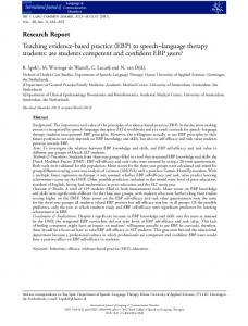


!['Strategic Approach for Safe Chemical and Energy Industries' [pdf]](https://m.moam.info/img/260x300/strategic-approach-for-safe-chemical-and-energy-in_5a37266b1723ddefca6358af.jpg)


