of the physics of a real robot built at Sussex and the simulated vision involves ray-tracing computer graphics, using models of optical systems which could readily ...
Evolving Visually Guided Robots D. Cli�, P. Husbands, I. Harvey CSRP 220, July 1992
Cognitive Science Research Paper
Serial No. CSRP 220 The University of Sussex School of Cognitive and Computing Sciences Falmer Brighton BN1 9QH England, U.K.
A version of this paper appears in: Proceedings of SAB92, the Second International Conference on Simulation of Adaptive Behaviour J.-A. Meyer, H. Roitblat, and S. Wilson, editors, MIT Press Bradford Books, Cambridge, MA, 1993.
Evolving Visually Guided Robots Dave Cli� 1 2 and Philip Husbands1 and Inman Harvey1 1 School of Cognitive and Computing Sciences 2 Neuroscience IRC, School of Biological Sciences University of Sussex, Brighton BN1 9QH, U.K. davec or philh or inmanh, all @cogs.susx.ac.uk �
Abstract
creating an initial varied population of control architectures, and rating each according to whether desired behaviours are exhibited, evolutionary pressure can be exerted on the population. Using a suitably extended form of genetic algorithm, viable architectures may result.
We have developed a methodology grounded in two beliefs: that autonomous agents need visual processing capabilities, and that the approach of hand-designing control architectures for autonomous agents is likely to be superseded by methods involving the arti�cial evolution of comparable architectures. In this paper we present results which demonstrate that neural-network control architectures can be evolved for an accurate simulation model of a visually guided robot. The simulation system involves detailed models of the physics of a real robot built at Sussex and the simulated vision involves ray-tracing computer graphics, using models of optical systems which could readily be constructed from discrete components. The control-network architecture is entirely under genetic control, as are parameters governing the optical system. Signi cantly, we demonstrate that robust visually-guided control systems evolve from evaluation functions which do not explicitly involve monitoring visual input. The latter part of the paper discusses work now under development, which allows us to engage in long-term fundamental experiments aimed at thoroughly exploring the possibilities of concurrently evolving control networks and visual sensors for navigational tasks. This involves the construction of specialised visual-robotic equipment which eliminates the need for simulated sensing.
In this paper we present results which validate our proposals. We employed the Saga evolutionary principle 6] to develop neural-network control architectures for a simulation model of a real robot under construction at Sussex. The simulation system incorporates accurate physics, based on empirical observations of the real system, with added noise and uncertainty. The visual sensor capabilities are simulated using a ray-tracing computer graphics system 2]. Parameters governing the robot's sampling of its visual eld are under genetic control, and the resultant speci cations could readily be constructed from discrete components. Our results demonstrate that it is possible to evolve control architectures for visual guidance, using high-level evaluation functions which make no explicit reference to vision. The results presented here are all for robots operating in relatively simple environments, comparable to those used for testing some real visually guided robots (e.g. 4]) but not as visually complex as a typical cluttered o�ce environment. The computational costs of providing appropriately accurate simulation data scales very poorly as the complexity of the environment increases. In order to fully explore the possibilities of our methodology with more challenging tasks in increasingly complex environments, we have developed an approach which allows us to eliminate much of the computationally expensive simulation work. This involves using specially designed robotic equipment which allows for the use of `real' (optical) vision, while facilitating exploration of issues in the concurrent evolution of visual sensors and control networks for navigation tasks. Section 6 describes this work, which we have only recently commenced. This paper deals largely with practical issues: our methodological position is expressed in more depth in a separate paper 7]. For the sake of completeness, it is summarised brie�y in the next section.
1 Introduction Designing control architectures for visually guided mobile autonomous robots that exhibit adaptive behaviour is likely to be a very di�cult task. So di�cult, in fact, that we advocate the abandonment of approaches to the problem which involve solution by manual design. In place of design-by-hand, we propose using evolutionary techniques. Focus then shifts from specifying how the robot is to generate adaptive behaviours, to specifying what adaptive behaviours are generated. By 1
2 Background
lower than that used in conventional computational vision research.1 A cursory survey of some biology literature indicated that, for creatures such as insects or other arthropods which have very few photoreceptor units, the photoreceptors often have large angles of acceptance,2 and are distributed around the body so as to sample a wide visual
eld. These simple photoreceptor units are perhaps best not thought of as pixels in an image (or `tiles' in a retinal `mosaic'): a more appropriate approach is to consider the photoreceptors as simple local brightness detectors. For example, if the portion of the optic array directly above an animal suddenly goes dark while the rest of the optic array remains constant, it seems likely that something is about to drop on the animal from above, and rapid evasive action is probably a sensible adaptive behaviour in such situations. Of course, the animal doesn't have to construct any internal representations or reason about the cause of the darkness it just has to do something useful. For this reason, our work to date on evolving visually guided robots has concentrated on ultra-low-resolution vision, close in spirit to Braitenberg's Vehicles 1]. The simulated robot has been given a few photoreceptor units, which could realistically be added to the physical robot. This could be done using discrete components (e.g. photodiodes, phototransistors, or ldr's) with individual lenses, thereby creating an electronic compound eye, cf. 4] or by using conventional ccd cameras but impairing their optics by mounting sand-blasted glass screens in front of the lens so as to generate input images with focus-independent blur, prior to some coarse sub-sampling scheme. The simulated robot was equipped with vision by embedding it within the SyCo vision simulator system described in 2]. The SyCo simulator was developed for studying issues in visual processing for control of an airborne insect, but only minor alterations were required: the `altitude' was clamped at a constant value, because the robot is a wheeled vehicle travelling on a �at �oor and the visual sampling pattern, which is xed in SyCo had to be placed under genetic control. The SyCo simulator synthesizes vision by means of a computer graphics technique called ray-tracing (see e.g. 5]). This is a method which involves instantaneous point-sample estimates (`rays') of the relevant projection integrals, and so aliasing is a common problem. Put most simply, aliasing is a problem where insu�cient samples are taken to give an accurate impression of the
In another paper 7], we have presented arguments supporting the notion that an evolutionary approach to the design of robot control systems can be expected to supersede design by hand. In that paper we also explored issues arising from the adoption of an evolutionary approach and gave results of preliminary simulation experiments in evolving control architectures for simple robots equipped with a few touch-sensors: four `whiskers' and two `bumpers'. For reasons explained in 7], the control architectures were based on a particular kind of `neural' network, and central to the evolutionary mechanisms is the notion of a gradual incremental development, building on already existing capabilities. The results of the experiments with purely tactile sensors are highly encouraging: for certain types of evaluation function, the robot population can evolve to the point where genuinely useful behaviours emerge. Nevertheless, the proximal nature (and low dimensionality) of the robot's sensors forever constrain it as unable to go beyond primitive `bumping and feeling' strategies in navigating around its environment. For more sophisticated navigation strategies, based on distal information, the addition of visual sensing capabilities is required. Brie�y, the rationale for adding vision is that it allows for much more sophisticated behaviour patterns (e.g. location recognition in navigation). The remainder of this paper discusses our experiences in adding visual processing capabilities to the simulated robot.
3 And Then There Was Light Rather than imposing on the robot some visual sensors with xed properties, it seemed much more sensible, and in keeping with our incremental evolutionary approach, to investigate the concurrent evolution of visual sensors and control networks. In essence we have started with simple very low resolution devices coupled to small networks, and will work towards higher resolution devices made useful by more complex networks generating more sophisticated behaviours. Major factors a�ecting how this occurs are under evolutionary control.
3.1 Preliminaries Because the simulated robot is based on a physical robot under development, it is necessary to su�ciently constrain the visual processing capabilities available under evolutionary control, so that whatever designs evolved are (at least in principle) capable of being built using available hardware. In essence, this meant opting for very low visual resolution. The total number of pixels had to be at least two or three orders of magnitude
1 In `conventional' computer vision, image sizes of 512 � 512 (i.e. 262144 pixels) are not considered large. 2 The acceptance angle of a photoreceptor can be de ned as twice its maximum incidence angle, where the maximum incidence angle is the largest angle, measured as eccentricity o the 'receptor's visual axis (\direction of view"), at which an incoming ray of light can still have a signi cant e ect.
2
(visual) signal being sampled. To limit the e�ects of aliasing, the SyCo code was con gured to determine each photoreceptor's activity by averaging the readings from several rays per simulated receptor, distributed across that receptor's visual eld. This provides more accurate estimates of image brightness in the receptor's eld of view. However, it is important to keep the number of rays per receptor relatively low. This is for two reasons: one pragmatic, the other theoretical. First, ray-tracing is a computationally expensive process, so using fewer rays per receptor saves processing time. Second, real vision is not an arbitraryprecision process. In vision, noise is inescapable, and noise e�ectively reduces a continuum of brightness levels to a small number of discrete ranges (e.g. 9]). By limiting the number of rays per receptor, the precision of the brightness-value estimate is correspondingly reduced. The simulated robot must be able to cope with noisy limited precision perception, because that is all the real world has to o�er.
AoA
AoA
Ecc
Ecc
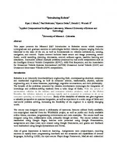
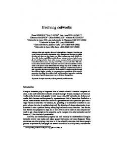
Figure 1: Angle of acceptance and eccentricity for the two-
photoreceptor robot. A top-down view of the robot, and the relevant angles.
3.2 Particulars 3.2.1 Vision
In keeping with the minimal incremental approach advocated in 7], we have commenced our studies by exploring the e�ects of adding just two photoreceptors to the sensor suite (bumpers and whiskers) described above. Taking a cue from biological vision, the sensors are situated in positions which are bilaterally symmetric about the robot's longitudinal midline. Having only two receptors introduces manifest limitations on the classes of behaviours that can be expected to evolve in the robot. Assuming that the receptors sample largely distinct portions of the optic array, the only information the robot can access concerning its visual surroundings is likely to be limited to the raw data (the brightness levels recorded by the photoreceptors) and summary statistics such as the average brightness, or the di�erence between the two signals. Nevertheless, the acceptance angles of the photoreceptors, and their positions relative to the longitudinal axis, can be varied under genetic control. The two receptors are constrained to have the same angle of acceptance, which is coded as a binary number represented as a bitvector eld in the robot's genome. A second bit-vector
eld in the genome governs the eccentricity of the photoreceptors, measured o� the robot's longitudinal axis. Figure 1 illustrates these two angles. The details of the genetic coding of the acceptance angle � and the eccentricity � of the two photoreceptors is straightforward. In principle, the angles are constrained to the ranges � 2 (0� �] � R and � 2 0� �=2] � R, but the use of a bit-vector genome forces a discretization of these ranges. Both angles are represented by four
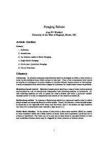
Figure 2: A cartoon of an appropriate robot: the angle of acceptance can be altered using zoom lenses. The eccentricity can be altered by rotating the cameras on their stalks.
bits in the genome, giving a choice of 24 = 16 discrete values for each angle, i.e. a total of 28 = 256 con gurations of � and � . If the integer values represented by the genome elds for � and � are i� and i� respectively (i� � i� both 2 f0� 1� : : :� 15g � N), then � = (1+i� )�=16, and � = i� �=15. The genome is currently being extended to allow the number of photoreceptors to be placed under genetic control. In the current two-receptor model, each receptor has a square cross-section to its receptive eld. As an anti-aliasing measure, sixteen rays, arranged on a regular 4 � 4 grid, are traced for each pixel. All experiments to date have involved evolving architectures which enable the robot to guide itself within a closed cylindrical room. The curved walls of the room are black, while the �oor and ceiling are white. Figure 3 3
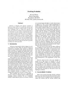
Figure 3: Illustration of the ray-tracing system. The left-hand gure shows the robot's position and orientation within the cylinder, which has black walls and white �oor and ceiling. At upper right is a pair of relatively high-resolution images, traced from the robot's position inside the cylinder. The lower-right gure shows the two 4 � 4 images traced prior to averaging, with = 1 571 and = 0 628. The nal two photoreceptor brightness levels are derived by averaging the 4 � 4 images. �
�
:
:
illustrates output from the ray-tracing system in this environment Figure 4 illustrates the e�ects of varying � and � .
3.2.2 Physics
The simulation involves a realistic physics for determining the e�ects of the robot moving across the �oor and colliding with the walls. As described in more detail in 7], the simulated robot is cylindrical in shape with two wheels towards the front and a single trailing rear castor. The wheels have independent drives allowing turning on the spot and fairly unrestricted movement across a �at �oor. Outputs from the robot's control networks feed direct to the wheel drives. Depending on the strength and sign of their signal, the wheels rotate at one of ve rates: full speed forward full speed backward half speed forward half speed backward and stationary. The continuous movement of the robot is simulated by polling the network outputs at an appropriate rate. At each step of the simulation the next position and orientation of the robot is calculated using the appropriate kinematic equations (with a suitable amount of noise added). Collisions are handled as accurately as possible, based on observations of the physical system. Brie�y, if the robot collides with a high velocity normal to the surface it undergoes a noisy re�ection with a rotation determined by its original direction of motion if it collides at low speed its behaviour depends on the angle of incidence { it may rotate until normal to the obstacle or it may skid around until it is parallel.
Figure 4: Varying and . For all the gures, the robot's posi�
�
tion is the same as in Figure 3� the left-hand column shows the pair of 4 � 4 images, while the right-hand column shows the respective higher-resolution images.
experiments described below was to explore the possibility of evolving robots which could use their visual perception capabilities to avoid collisions with the walls prior to making physical contact with the wall via one of their tactile sensors. Using intentional language, we can say that the robot learns to predict, from visual data alone, that a collision is likely in the near future, and takes appropriate evasive action. We felt this was a suitably low-level task for preliminary experiments. More complex behaviours are currently being evolved from this one. So, the rst task set for our robots was to roam around an empty cylindrical room without hitting the walls. The two-photoreceptor robot has, in theory, su�cient sensory data to avoid the dark walls. Examination of the visual data shown in Figures 3 and 4 con rms this. For example, a useful strategy would be: if the di�erence between the brightness levels of the two receptors is greater than some threshold, dependent on the values of � and � , then the robot should turn in the direction of the brighter receptor. The evolutionary process requires an evaluation function E by which the tness of individuals in the pop-
4 Experiments Results from earlier experiments discussed in 7] demonstrated that our methods could be used to evolve robots which could engage in primitive tactile-based navigation patterns such as wall-following. The primary goal in the 4
4.1 Evolutionary Mechanisms
ulation can be rated. We have found three evaluation functions useful:
Populations of robot genotypes underwent evolution guided by selective pressures based on the evaluation E1 = D(t) functions given above. The genotype of each robot con8t sists of two chromosomes: one codes for the neural archi�X ! �X ! tecture and the other for properties of its visual sensors. E2 = D(t) � B(t) As was described in Section 3.2.1, the visual sensor chro8t 8t mosome is a simple xed length bit string which decodes �X ! �X ! into a set of parameters giving angle of acceptance and E3 = D(t) � G (t) eccentricity of the robot's two photoreceptors. The neu8t 8t ral architecture chromosome is more complex, needing a where: fairly involved process of decoding. The coding and its 8t denotes all time, i.e. the lifetime of the interpretation are described brie�y below, but further individual details can be found in 7]. D(t) denotes the distance travelled on timestep t The robots `neural-style' control networks have a xed B(t) denotes the average brightness of number of input units: one for each sensor. In this case the two photoreceptors at time t there are eight: front and back bumper, two whiskers G (t) denotes a Gaussian function of the robot's toward the front and two whiskers toward the back, and distance from the centre of the cylinder at time t the two photoreceptors, or `eyes' (cf. Figure 1). The networks also have a xed number of outputs two The reasons behind choosing these evaluation funcfor each of the motor drives. As all of the units are noisy tions were straightforward. The function D, used in all linear threshold devices (as described in 7]) with outputs the evaluation functions, encourages the robots to move in the range 0:0� 1:0] � R, two units are needed to give (otherwise the best way of avoiding bumping into walls the motors a signal in the range ;1:0� 1:0] � R, so that is simply to remain stationary). forwards and backwards motion is possible. If the output E1 only employs D, so the robots which travel furthest signals from these four output units are labelled So1 to in their lifetimes are rated as the ttest: nevertheless, S , then the left motor signal is the di�erence between o 4 the mechanics of the collision simulation still penalises S and S , while the right motor signal is the di�erence o 1 o 2 robots which collide with the walls at all often. between S and S . o 3 o 4 E2 is an extension of E1 : the inclusion of the sum of As well as these units these network chromosome codes brightness B introduces a selection pressure which is exfor a number of `hidden' units. The number is not preplicitly vision-oriented. As a robot approaches a wall, speci ed { the chromosomes are of variable length. The the value of B drops because the wall will tend to ocbulk of the chromosome codes for the connections becupy more of the visual eld of the two receptors. PSo, tween the units. These are unrestricted complex recurrobots which over their lifetime have a high value of B rent nets are quite possible, as will be seen below. are ones which have tended to avoid approaching walls, The networks are real-valued and continuous { think of and are hence rated as tter than those which spend a them as analogue circuits with real-valued signals continlot of time moving close up to walls. uously propagating { which gives them many desirable E3 is a more subtle version of E2. Rather than explicdynamical adaptive properties. A link may be one of itly rate the tness according to total brightness over a two types: normal or veto this property is under genetic lifetime, we rate the robots on the basis of how much of control. A normal connection joins the output from one their time is spent near the centre of the cylinder's �oor unit to the input of another, with unity weight. A veto disk. This is done by measuring the robot's distance d from the �oor-centre at time t, and then weighting the connection is a special in nitely inhibitory connection between two units. If there is a veto connection between distance by a Gaussian G of the form: units a and b, and a's output exceeds its veto threshold G = exp(;d2 =c) then all normal connection outputs from b are switched for some constant c, which ensures that G � 0 for d >� to zero. The veto threshold is always signi cantly higher 2r=3, where r is the cylinder's radius. So, while there is than the lower threshold for a neuron's sigmoid transfer no explicit mention of vision in E3, it is hoped that the function. The genetic algorithm used is in accordance with robots will evolve to the point where they use their visual input to ensure they are always some distance away from the Saga principles 6]: crossover allows only gradual changes in genotype length. Although we only present the walls. Section 5 discusses the results from using these evalu- results here from simple preliminary experiments, we are ation functions. Before that, we describe some details of currently evolving more complex nets from those developed here, still in keeping with the incremental Saga the evolutionary mechanisms used.
X
5
approach. Within this framework, the aims of our rst set of simulation experiments was to try and evolve coupled networks and visual sensors capable of generating interesting behaviours.
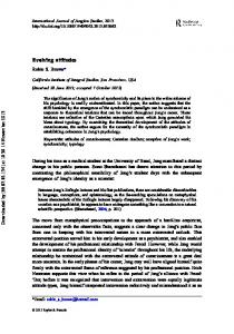
5 Results All of the following results were achieved with population size 40, a crossover probability of 1 and a mutation rate of the order of one bit per genotype. The visual sensor and network chromosomes are crossed and mutated separately, but both contribute to the resultant phenotype: the sighted robot. Rank based selection was used with the ttest individual being twice as likely to breed as the median individual. So far the experiments have only been run for a relatively small number of generations, given the expense of the ray tracing and the fact that each individual is evaluated multiple times, as described below. Each individual in each generation was run four times from random starting positions and orientations. Each run was for a xed number of time steps. The tness of the individual was taken as the worst score from their four runs. This strategy is used to encourage robustness, remembering that there is noise at all levels in the system. A ne-time-slice simulation was used as a close approximation to a continuous system. At each time step the sensor readings are fed into the neural network. The continuous nature of the networks was simulated by running them (synchronously updating all unit inputs and outputs) for a number of iterations (about 100, but with a variance to counter distorting periodic e�ects) and then converting the outputs to motor signals. The new position of the robot is then calculated, using the model physics described in Section 3.2.2. By using suitably ne time-slices, this mode of simulation is more than adequate although we are working on more subtle techniques to allow fully asynchronous event-based simulations. The rst set of experiments used evaluation function E1, a simple integration of distance moved. Comparisons were made between sighted and blind robots (which used only the six touch sensors). Both did well although the evolved behaviours were quite di�erent in the two cases. The blind robots evolved to make looping elliptical movements like that shown in Figure 5. The strategy seems sensible as it tends to keep the robot away from the walls. The networks quickly evolved to the state where sensory inputs triggered changes in directions which sped the robot away from the wall. See Figure 10, later, for an example of such behaviour. The sighted robots did better, tending to keep moving by staying away from the walls using visually guided behaviours like those shown in Figure 8, described in more
Figure 5: Typical path of blind robot under evaluation function E1. The arrows show the orientation of the robot at each time step, and their length is equal to the diameter of the robot.
Figure 6: Evolved behaviour of sighted robot under evaluation function E2 .
detail later. The second set of experiments use E2. This evaluation function makes explicit use of the visual signal, so a comparison with blind robots was not sensible. The behaviours which evolved were unexpectedly simple but made perfect sense. A very t and robust behaviour which rapidly dominated is shown in Figure 6. The robot evolved to have photoreceptors with high angle of acceptance and high eccentricity, and it turns in a tight circle by jamming one motor full on and one o�. Turning in a circle at full speed rapidly moves the robot away from the wall if it collides, P as shown in Figure 6. So this strategy tends toP maximise D(t), but it also gives a very high value for B(t) given that this visual signal is high except if a photoreceptor is close to and pointing towards a wall. The graphs of visual signals against time look like those shown in Figure 7. The third set of experiments, using E3, produced the most interesting behaviours. Remember the Gaussian function, G (t), drops o� sharply towards the walls. Early on, the circular motion behaviour predominated as shown in Figure 7. It can be seen that there is no correlation between visual signal and motor output vision is not yet being used. This P behaviour is not very robust as it scores poorly on G (t) if the robot starts o� near a wall. But within a few generations the much more robust behaviour of Figure 8 appeared. Here the robot is making clear use of vision to keep it away from the walls and so score well 6
FB
BB
FRW Left Motor
BRW
BLW
FLW Left Eye
Figure 7: Fittest behaviour of sighted robot in very early generations under evaluation function E3 .
Right Motor
Right Eye
FB=Front Bumper RB=Rear Bumper FRW=Front Right Whisker BRW=Back Right Whisker FLW=Front Left Whisker BLW=Back Left Whisker
"Normal" Connection Veto Connection Connection from/to sensor/actuator Processing Node
Figure 9: Evolved network responsible for generating the behaviour shown in Figure 8
correlated behaviour. In earlier generations, the tactile sensors seem to have been used much more. By the later stage at which the behaviour shown was produced, vision is dominant. Examination of the wiring strongly suggests that many of the tactile sensor input nodes are essentially being used as `internal' nodes: vision keeps the robot away from the walls and hence avoids the possibility of turning the sensors on, thereby rendering the tactile input units virtually redundant later, over a number of generations, the `input' units are employed for other uses. This is a good example of the strongly opportunistic nature of evolution. It pays no regard to the initial characterisations given to the nodes. One of the most remarkable phenomena we observed was the emergence of networks involving oscillatory circuits built up from complicated loops of veto and normal connections. Under certain initial conditions, when the robot's visual signals became high these circuits would periodically turn the motors on and o� so that the robot moved slowly through the bright areaPof the room. Although this reduces the score on the D(t) component P of E3 it is e�ective in increasing the score on the G (t) component. The mature evolved networks typically appeared rather complex for their given tasks. We are currently exploring methods of exerting an evolutionary pressure towards simpler networks, by introducing costs for link creation in the evaluation functions, and by employing neuron models with more �exibility (e.g. variations in time delays and/or connection strengths). Blind robots did fairly well on the E3 evaluation function too directly evolving strategies to move well away
Figure 8: Later evolved behaviours under E3 . on the Gaussian function. The graphs in Figure 8 show the visual signals and the motor signals (with noise removed for easier interpretation) plotted against time. The basic strategy is to jam one motor on full speed and one on half speed (in this case it is moving backwards) 3 to move in an ellipse. But when the visual signal drops, one of the motors is turned o�, causing the tight turns shown in the gure. The sensors evolved to have a fairly high angle of acceptance but a low eccentricity (both `eyes' clearly pointing forward) which makes sense in the context of this behaviour. So here we see a clear correlation between visual signal and motor output vision is being used to great e�ect. Examination of the evolved network, shown in Figure 9, that generates the behaviour in Figure 8 reveals a complicated connectivity with many indirect feedback loops and subtle uses of veto connections. The jammedon right motor is achieved by the relevant output unit feeding back into itself and having no other inputs. Once internal noise generates an input to the unit it will amplify and then circulate forever (at the moment signals do not attenuate in time, although of course veto connections can turn parts of the net on and o�). Visual signals feeding into the left motor outputs provide its visually 3 We, as experimenters, have designated a particular mode of movement as `forward' (motor signals positive), but clearly in this simple environment there is a duality between forwards and backwards movement. `Running towards light' and `runnning away from dark' are equivalent behaviours.
7
increasingly complex environments and with more challenging tasks. But there is a severe limitation on how much further the work can be taken in its current form: the computational costs of simulating vision and realistic physics mean that vast quantities of computer time are taken up with providing an accurate `virtual reality' for the simulated robots. For this reason, we are moving into a second phase in our work. This reduces our reliance on simulation, by using an accurately controllable real-world robot linked to o�-board processing. We call this system `toytown'. The toytown experimental setup described below is now under development and we expect our rst results in the near future. The apparatus has been designed to allow us to engage in long term fundamental experiments aimed at thoroughly exploring the possibilities of our evolutionary methodology. In particular, we aim to explore the concurrent evolution of control networks and visual sensors for navigational tasks. As in the experiments described earlier, details of the animat's visual sensing and neural architecture are under genetic control.
Figure 10: Evolved behaviour of blind robot under E3 . from the wall, such as reversing, as shown in Figure 10. The change in direction of the robot in the middle of its path (this one is moving forwards) is a clear case of reversing. In each of the experiments the networks were capable of generating a wide range of behaviours. This was due to their dynamical properties and gave important advantages. Although Hebbian-style learning is on our agenda, we can probably delay its use for a while given the power of these continuous dynamical nets.
6.1 Toytown
Our experiences to date have con rmed earlier intuitive notions that simulation of visual inputs is computationally horrendous | this is directly associated with the usefulness of vision, in that it gives inputs from a vast range of the environment both far and near. So the incentives for working with real rather than simulated vision are even higher than with the other senses. Active vision for a robot in a real world requires something like a camera moving with the robot through that world, which for experimental purposes normally requires a decision to be made between having computational processing of visual inputs done onboard the robot, or o�board via some link to more powerful stationary computers. Both of these choices have negative factors associated, either the size and weight of onboard computation, or the problems of radio links and tangled umbilical cables. So for experimental purposes we have devised a third method, which allows a miniature robot with active vision, with the robot size e�ectively only a few cms across, to roam freely through an environment set up by the experimenters. The environment could be a `toytown', although the word `toy' here only refers to the size. It is a real world that the robot is in, with real-world vision problems. A gantry is set up above a �at surface, with a horizontal girder able to move west and east by means of a stepper motor, providing the X-coordinates of the robot. Along the girder another stepper motor allows movement of a platform north and south (the Y-coordinates). From the platform a ccd camera is xed pointing vertically downwards. A conical mirror is xed with its axis along
6 Discussion and Further Work The results show quite clearly that, in all three cases, the robot design evolved to satisfy the evaluation function. Furthermore, there was a clear behavioural di�erence between those robots which used vision, and those which were unsighted. Interesting results have been achieved with relatively small populations and after realtively few generations. We think this is largely due to the particular type of networks we have chosen to use. They have properties which appear to result in a search space highly suited to evolutionary techniques. The SAGA principles of gradual and incremental evolution should help to keep the search space constrained so that small to medium sized populations can be used throughout our work. Our work to date has involved evolving robots which move around an empty cylindrical room without hitting the walls. Work is currently in progress on extending the robot's behaviour so it can move in cluttered envirnments without collisions. However, the computational costs of the ray-tracing system scales roughly in proportion with the number of objects in the robot's environment: simulating vision in cluttered environments soon imposes deeply problematic computational burdens on the overall system. Nevertheless, the results so far have been su�ciently successful that our approach bears further exploration in 8
the current level of evolution. Time can be slowed down to a rate appropriate to computational resources. As cognitive processing becomes more computationally demanding the speed of movement of the creature and other dynamic objects in the environment can be made as slow as is desired. The highly controllable nature of the apparatus means that experiments are repeatable and very long runs can be achieved without any human intervention. This means that, for each generation, each member of the population can be evaluated without recourse to simulation. A succession of tasks of increasing complexity can be set for such a robot. Automatic evaluations for each task allow a succession of tests, and the evolutionary process, to continue without immediate human intervention. A possible succession of tasks would be: Movement towards an `object' (a prominent dark mark, perhaps). Rotation (virtual rotation via software resampling of camera input) to face a moving object. Avoidance of obstacles. Movement between two objects. Movement centrally along a striped corridor. Identi cation of, and movement through, `doorways'. Exploratory movement within a simple maze. Identi cation of particular `situations' within such a maze or environment, and return to them after exploration. Development of `place recognition' by navigation through the environment between speci ed points via self-selected intermediary places. Navigation and interaction with a dynamic world. Performance of previous tasks but subject to arbitrary polarity reversal of the motor outputs. The outputs from the controller provide signals to the motor drives (with the deliberate addition of noise if desired) which e�ectively allow the robot to move continuously and freely in this world. The robot is to all intents and purposes autonomous. However, although it does not `know' its absolute position and orientation, this information is always available to the experimenters. This is extremely useful for automatic tness evaluation, repeatability, repositioning and so on.
Figure 11: The toytown gantry system. See text for further details.
the camera axis, some cms below the lens and occupying its eld of view. The camera and mirror can be moved together with its supporting platform in the X and Y dimensions. Vertical movement relative to the platform can also be provided to give the Z dimension. The mirror itself can be considered as the body of the sighted arti cial creature which can move through the environment provided for experimental purposes. A sketch of the toytown system is shown in Figure 11. Potentially a 360� eld of view is available, although software sampling (under `genetic' control) can provide any number of virtual pixels or photoreceptors facing any speci ed direction rotation of this visual eld about the vertical axis can be e�ected in software, as can any number of strategies for sampling the visual eld (cf. 3]). A system of servo motors, racks and pinions can provide an accuracy of movement of plus or minus one millimetre. Touch sensors around the conical mirror complete the `body' of the robot. The robot's control network is simulated o�-board on a computer. The sensory inputs are fed into the controller via an umbilical cable and interfacing cards. In a similar way the controller sends motor commands to the various actuators. The `body' of the robot is only the size of the conical mirror plus touch sensors, and subject only to its attachment to the camera above, and hence to the gantry, can be moved anywhere in an experimental setup. This setup can be suitably small, and easily altered. In this way all of the real world characteristics of moving around in a noisy visual environment are retained, with a number of advantages for experimental purposes over a wheeled ground-based autonomous robot: There are no problems with tangled umbilicals, and on-board power supplies and computers are not an issue. The environment is easily changed - it can be made less structured or more dynamic or whatever suits 9
The `Toytown' environment has some similarities with the `Tinytown' environment at Rochester 8]. However the latter has a camera pointing down that can move only in two dimensions, giving the equivalent of `low-�ying aerial photographs'. In contrast, the toytown robot has a (virtual) rotational degree of freedom, and can travel in and amongst the objects of a 3-D world, with a horizontal
eld of view manipulable between 0� to 360�.
5] A. S. Glassner, editor. An Introduction to Ray Tracing. Academic Press, London, 1989. 6] I. Harvey. Species adaptation genetic algorithms: A basis for a continuing SAGA. In F.J. Varela and P. Bourgine, editors, Towards a Practice of Autonomous Systems: Proceedings of the First European Conference on Arti�cial Life (ECAL91), pages
346{354. M.I.T. Press | Bradford Books, Cambridge MA, 1992. 7] I. Harvey, P. Husbands, and D. T. Cli�. Issues in evolutionary robotics. Technical Report CSRP 219, University of Sussex School of Cognitive and Computing Sciences, 1992. 8] R. C. Nelson. Visual homing using an associative memory. Biological Cybernetics, 65:281{291, 1991. 9] M. V. Srinivasan, S. B. Laughlin, and A. Dubs. Predictive coding: a fresh view of inhibition in the retina. Proc. R. Soc. Lond. B, 216:427{459, 1982.
7 Summary and Conclusions As further support of our claims in 7], we have presented early results from experiments in evolving network processing architectures for mobile robots. Using networks of relatively constrained processing units (`neurons'), and simple evaluation functions, we have been able to evolve visual control architectures, even when the evaluation function is not de ned in terms of monitoring visual inputs. The results have demonstrated the feasibility of the approach, but the computational costs of simulating vision have lead us to develop a method which allows for a mix of `real' vision and evolutionary methods, using readily available hardware. The `toytown' project is at an early stage, but our current results are su�ciently promising that we are con dent of future success. Watch this space.
Acknowledgements
Many thanks to Linda Thompson for help in the preparation of this paper. Inman Harvey is supported by a Serc grant.
References 1] V. Braitenberg. Vehicles: Experiments in Synthetic Psychology. M.I.T. Press | Bradford Books, Cambridge MA, 1984. 2] D. T. Cli�. The computational hover�y a study in computational neuroethology. In J.-A. Meyer and S. W. Wilson, editors, From Animals to Animats: Proceedings of the First International Conference on Simulation of Adaptive Behavior (SAB90), pages 87{
96, Cambridge MA, 1991. M.I.T. Press | Bradford Books.
3] D. T. Cli� and S. Bullock. Adding `foveal vision' to Wilson's animat, 1992. Forthcoming. 4] N. Franceschini, J.-M. Pichon, and C. Blanes. Real time visuomotor control: from �ies to robots. In Proceedings of the 1991 International Conference on Advanced Robotics, Pisa, 1991.
10